


Quick Answer: Specify the Function Before the Product Name
A fiber optic adapter aligns two connector ferrules so they can form a removable connection. An optical coupler deliberately shares optical power among three or more ports. A bulkhead describes how an adapter or receptacle mounts through a panel or enclosure wall.
The difficult part is market language. "LC coupler" often means an LC mating adapter, while an "FBT coupler" is a power-branching device. The safe RFQ starts with the verb-join, split, tap, combine or pass through a panel-and then adds the interface, optical performance and mounting details. For the wider relationship among connectors, pigtails, patch cords and adapters, use Glory Optical's fiber connectivity selection guide; this article focuses only on the naming boundary that causes adapter, coupler and bulkhead purchasing errors.
1. Fiber Optic Adapter vs Coupler vs Bulkhead at a Glance
| Term | Primary function | Typical port logic | Does it intentionally split optical power? | Critical RFQ fields |
|---|---|---|---|---|
| Fiber optic adapter | Mechanically retains and aligns two connector ferrules | Two opposed mating interfaces; simplex or duplex body | No | Connector family, mode, polish identification, sleeve, flange, simplex/duplex, shutter and color |
| Optical coupler / splitter | Divides, taps or combines optical power | 1×2, 2×2 or another branching arrangement | Yes | Topology, wavelength, coupling ratio, insertion/excess loss, uniformity, directivity, PDL and package |
| Bulkhead adapter / receptacle | Creates a connector interface through a panel or enclosure boundary | Usually one inline optical path per port | Not by the term itself | Panel cutout, flange/nut/clip, wall thickness, sealing, dust cap, keying, torque and strain transfer |
A simplex adapter carries one removable fiber connection; a duplex adapter carries two. "Duplex" describes channel count in the adapter body, not a 50/50 power split. Glory's LC OM3 duplex high-low adapter, for example, is a two-channel alignment component for panel layouts. It is not an optical branching device.
2. Why "Coupler" Can Mean Two Different Components
Legacy catalogue language is the source of most confusion. A female-to-female SC or LC adapter is sometimes sold as an "SC coupler" or "LC coupler" because it couples two connectorized cables. In optical-component engineering, however, a coupler normally means a device whose internal optical region transfers power between fibers or waveguides.
The two uses can appear on the same supplier website. Glory's LC multimode high-low adapter is described in market language as an LC duplex coupler, but its function is ferrule alignment. Glory's fused fiber coupler uses FBT construction to create defined 50/50, 40/60, 10/90 and other power ratios. The product name alone does not safely distinguish them.
3. The Standards Draw a Clearer Functional Boundary
The standards do not organize these products by search-engine vocabulary. They organize them by interface and optical behavior.
- IEC 61754-20:2012+A1:2022 defines interface dimensions for the LC connector family.
- IEC 61754-4:2022+A1:2026 defines the SC connector family and includes mounted-adapter considerations.
- IEC 60875-1:2024 covers passive, non-wavelength-selective branching devices with three or more ports that share optical power in a predetermined way.
- IEC 61300-3-4:2023 provides attenuation measurement methods for optical components.
- IEC 61300-3-35:2022 provides end-face inspection procedures and criteria; it explicitly notes that visual inspection does not replace attenuation and return-loss qualification.
This standards map prevents a common documentation mistake: citing IEC 61754 interface compliance as if it proves the finished adapter's insertion loss, durability or environmental performance. Interface dimensions, optical performance and production quality are separate evidence layers.
Certification is not a product test report
ISO 9001:2015 is a certifiable quality-management-system standard. Glory's company and compliance page lists ISO 9001:2015 documentation for its manufacturing and management processes. That supports process control and traceability; it does not by itself certify that an individual adapter meets a 0.20 dB limit or that an FBT coupler has the ordered split ratio. Request the product drawing and batch optical results as well.
4. A Fiber Adapter Creates Alignment, Not a New Optical Route
Inside a conventional LC, SC or FC adapter, an alignment sleeve holds the two ferrules on a common axis while the connector latches or threads provide retention. The fibers remain in the two plugs; the adapter body does not contain a splitter chip or fused coupling region.
The Fiber Optic Association's adapter guidance distinguishes plastic, metal and ceramic alignment sleeves and recommends ceramic where precise, repeatable single-mode alignment or repeated testing is required. The purchasing lesson is not that one sleeve wins every application. It is that "SC adapter" is incomplete when the sleeve, mating-cycle requirement and mode are not stated.
Six adapter decisions that are independent
| Decision | What it controls | Common error |
|---|---|---|
| LC, SC, FC, ST or MPO/MTP | Physical connector interface and density | Ordering by color without confirming the interface |
| Single-mode or multimode | Alignment precision and identification | Assuming every beige, blue or aqua body has the required sleeve |
| UPC or APC identification | Prevents incompatible connector end faces from being mated | Believing the adapter converts APC to UPC |
| Simplex or duplex | One or two independent connections per body | Interpreting duplex as optical splitting |
| Flanged, flangeless or hybrid | Panel retention and possible connector-family conversion | Leaving the panel cutout and latch method unspecified |
| Open, shuttered or dust-capped | Contamination control and access behavior | Approving a clean-room sample without defining field protection |
For connector-form-factor selection before choosing the adapter body, see Glory's LC vs SC vs FC vs ST guide. Then review the fiber optic adapter range by interface, sleeve, mounting and application.
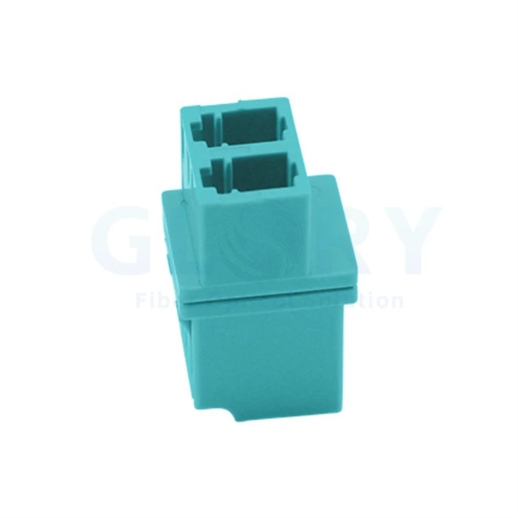
Real Glory product image: an LC OM3 duplex high-low adapter. Its two LC channels align two independent connector pairs; they do not create a 1×2 optical split.
5. An Optical Coupler Changes the Power Map
A true optical coupler has an internal optical interaction region. In an FBT device, fibers are fused and tapered so a defined portion of optical power transfers between cores. A 1×2 device can send equal power to two branches or create an unequal monitoring tap. This places the coupler in the link budget, not merely in the mechanical-connection schedule.
The current IEC 60875-1:2024 description gives the decisive test: a passive device with three or more ports shares optical power among those ports in a predetermined fashion. Glory's FBT vs PLC splitter selection guide expands the technology choice, while this article addresses whether the BOM item is a branching device at all.

Real Glory product image: a connectorized 1×2 fused fiber coupler. Unlike an adapter, the internal FBT region deliberately distributes optical power between the output branches.
Do not specify only "1×2 coupler"
- State 1×2 or 2×2 topology and which port is input, through or tap.
- State operating wavelength or wavelength window.
- State coupling ratio, for example 50/50 or 10/90, and the permitted tolerance.
- State insertion loss by output port, excess loss, uniformity and directivity.
- State fiber type, pigtail construction, connectorization and package dimensions.
- State controlled, outdoor or other environmental category and the applicable qualification evidence.
For projects needing non-standard tap ratios, Glory's optical fiber coupler range provides the relevant product path. FTTH projects needing uniform higher-count distribution should separately evaluate the fiber optic splitter range.
6. "Bulkhead" Describes a Boundary and Mounting Method
In normal panel language, a bulkhead adapter sits through a cutout so connectors can mate on opposite sides of a panel. Depending on the design, it may use a flange and screws, snap clips, a retaining nut or a hardened enclosure receptacle. The word does not determine LC versus SC, APC versus UPC, single-mode versus multimode or weather sealing.
A manufacturer example makes the distinction concrete. SENKO's IP-Solid SC bulkhead adapter is explicitly a terminal/closure-mounted receptacle with an IP68-rated body. Its page also limits the IP statement to the tested cable and procedure and recommends retesting other cable combinations. That qualification is important: an indoor snap-in adapter and a sealed outdoor bulkhead can share an SC interface without sharing environmental performance.
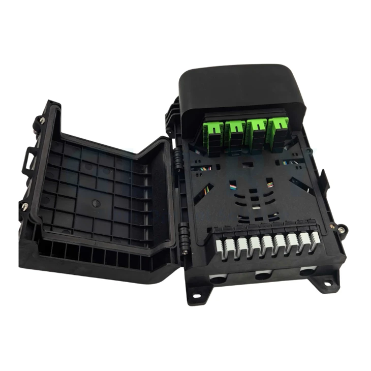
Real Glory enclosure image: the open 16-core FTTX termination box shows how adapter positions become part of a complete mounted assembly. Panel fit, port sealing and internal routing must be approved together.
When the adapter will be installed into an FTTH box, use Glory's fiber optic termination box selection guide to confirm enclosure capacity, sealing and mounting. For rack environments, confirm adapter-panel compatibility through the fiber optic patch panel range.
7. The Loss Difference Is Large Enough to Break a Link Budget
The adapter-versus-coupler naming error is not semantic. It changes the optical topology.
Glory's public SC adapter specification lists insertion loss, repeatability and alternating loss at no more than 0.20 dB. The public fused-coupler table lists a typical 3.6 dB loss on each branch for a premium-grade 50/50 device, or 10.8 dB and 0.9 dB for the two branches of a premium 10/90 device.
One adapter junction at its listed limit: ≤0.20 dB.
One premium 50/50 FBT coupler branch: typically 3.60 dB.
Difference on that path: approximately 3.40 dB before adding any extra connectors, splices or engineering margin.
The 50/50 split alone has an ideal division loss of 3.01 dB; real devices add excess loss and imbalance. This is why an optical coupler cannot be treated as a low-loss way to extend two patch cords. Conversely, an adapter cannot replace a monitoring tap because it does not create a second optical output.
A compact 12-port panel example
If a design contains eight removable adapter junctions and each is budgeted at the public 0.20 dB limit, the adapter allowance is 1.60 dB. Adding one 50/50 FBT branch to a monitored path changes that path by about 3.60 dB, more than twice the allowance for all eight adapter junctions. The final design must use project acceptance limits and measured results, but this screening example shows why the BOM must distinguish alignment points from branching points.
8. The Glory Component Naming Gate: Eight Fields Before Quotation
The following quotation-stage framework is designed to translate ambiguous catalogue language into a manufacturable and testable line item. It is a Glory engineering planning method, not an IEC certification scheme.
- Required action: join, extend, split, tap, combine or pass through an enclosure wall.
- Optical topology: one inline path, two independent duplex paths, 1×2 branch, 2×2 branch or another port map.
- Interface: LC, SC, FC, ST, MPO/MTP or a defined hybrid pair.
- Fiber and polish: single-mode or multimode; APC, UPC or PC; never rely on body color alone.
- Mechanical format: simplex/duplex, flange/flangeless, clip/nut/screw, shutter/cap and panel cutout.
- Optical limits: insertion loss, return loss or directivity, coupling ratio, excess loss, uniformity, PDL and wavelength range as applicable.
- Environment: indoor rack, controlled cabinet, outdoor box, hardened terminal, temperature range and ingress requirement.
- Evidence: drawing, current datasheet, applicable standard, sample test method, batch report, labeling and packing traceability.
If Fields 1 or 2 are missing, the supplier cannot reliably know whether "coupler" means a mating adapter or a branching device. If Field 7 is missing, "bulkhead" cannot establish whether a normal panel adapter or a sealed outdoor receptacle is required. Glory's OEM/ODM review process can use this information to configure adapters, FBT couplers, loaded panels and termination boxes under one controlled BOM.
9. Test the Mated System, Not Just the Plastic Housing
An adapter is mechanically simple, but its field result depends on the two connector end faces, ferrule geometry, alignment sleeve, cleanliness and mating force. Acceptance should therefore identify the full mating combination and test method.
| Evidence | Adapter / bulkhead | Optical coupler | Why it matters |
|---|---|---|---|
| Interface drawing | Connector family, keying, panel cutout and retention | Port labels, package, pigtail exits and connectorization | Prevents mechanically incompatible supply |
| Optical test | Mated-pair attenuation and return loss where specified | Per-port insertion loss, excess loss, ratio, uniformity and directivity | Confirms the actual optical function |
| End-face record | Inspection before final mating | Required for connectorized ports | Separates contamination from component performance |
| Mechanical record | Retention, panel fit and mating durability | Pigtail strain relief and package integrity | Protects performance after installation |
| Environmental record | Temperature and sealing for the complete mounted port | Applicable component category and thermal response | Stops an indoor part from being approved for an outdoor assembly |
Use IEC 61300-3-4:2023 as an authoritative attenuation-method reference and IEC 61300-3-35:2022 for connector end-face inspection. Glory's practical connector cleaning and inspection guide converts the inspection requirement into a field workflow. A visual pass is important, but the IEC page explicitly warns that inspection does not replace optical performance measurement.
10. Glory Optical Product Starting Points
Choose the product family after the function has been released. The following links keep the article commercially useful without treating any public page as automatic project approval.


All product images are loaded from the linked Glory Optical product pages. Final supply follows the approved drawing, current datasheet and project-specific test requirements.
Send a function-defined RFQ
Include the required action, port map, connector interface, polish, sleeve, mounting, wavelength, loss limits, environment, quantity and documentation package. Glory Optical can then return a matched adapter, coupler or loaded-panel configuration.
Submit an RFQ Review OEM/ODM optionsFrequently Asked Questions
Q: Is a fiber optic adapter the same as a coupler?
A: Sometimes the market uses coupler as a synonym for a mating adapter, especially for LC-to-LC or SC-to-SC parts. In a functional specification, an adapter aligns two connector ferrules while an optical coupler splits or combines optical power. Define the function and port count instead of relying on the noun alone.
Q: What is a bulkhead fiber adapter?
A: A bulkhead fiber adapter is an adapter or receptacle designed to mount through a panel, enclosure wall or equipment face. Bulkhead describes the mounting boundary. It does not automatically mean the device splits light or that the completed port is weatherproof.
Q: Does a fiber adapter add insertion loss?
A: The adapter has no active optical circuit, but the complete mated connection formed by two connector end faces and the alignment sleeve contributes insertion loss and reflection. Evaluate the mated pair using the supplier's stated method and acceptance limit.
Q: Can APC and UPC connectors use the same adapter?
A: Do not mate APC and UPC connectors together. The polish belongs to the connector end face, while the adapter aligns the ferrules. Specify matching APC-to-APC or UPC-to-UPC interfaces and use housing color and labeling to prevent field errors.
Q: When should an FBT coupler be used instead of an adapter?
A: Use an FBT coupler when the design must divide or tap optical power, such as a 50/50 branch or a 10/90 monitoring tap. Use an adapter when the design only needs a removable connector-to-connector junction without intentional power splitting.
Q: What should a fiber adapter or coupler RFQ include?
A: State the optical function, port configuration, connector family, fiber mode, polish, simplex or duplex arrangement, sleeve material, mounting style, wavelength range, loss limits, environmental category, test method, labeling and required batch records.
Specify the Optical Action, Mechanical Boundary and Evidence
The shortest reliable distinction is functional: an adapter aligns, a coupler branches optical power and a bulkhead mounts an interface through a boundary. The catalogue terms overlap, so the RFQ must carry more information than the product noun.
For procurement, the decisive fields are the port map, connector interface, sleeve and polish identification, panel mounting, environmental scope, optical limits and test method. When those fields are linked to a drawing and batch record, the component can be evaluated as part of the installed link rather than as an isolated plastic part.
Authoritative Sources and Research URLs
- IEC 61754-20:2012+A1:2022 - Type LC connector family
- IEC 61754-4:2022+A1:2026 - Type SC connector family
- IEC 60875-1:2024 - Non-wavelength-selective fibre optic branching devices
- IEC 61300-3-4:2023 - Attenuation measurement
- IEC 61300-3-35:2022 - Connector end-face visual inspection
- ISO 9001:2015 - Quality management systems
- Fiber Optic Association - Adapter and sleeve guidance
- SENKO IP-Solid SC Bulkhead Adapter - panel and sealing example
- Glory Optical SC Adapter - public product specifications
- Glory Optical Fused Fiber Coupler - public loss and ratio table
Engineering note: Public product values in this article are quotation-stage references, not a guarantee for every configuration. Confirm the current drawing, datasheet, test method, ordered BOM and batch acceptance criteria before release.





