

FTTH / ISP Access
For GPON / XGS-PON access networks, residential broadband, rural fiber rollout, MDU access points and last-mile optical distribution. Glory Optical configures the passive path between OLT and ONT with closures, PLC splitters, FDB/FAT terminals, preconnectorized interfaces, drop cable and subscriber outlets.
Glory Optical solution scope
One passive network package from feeder node to subscriber outlet
We organize the outside-plant hardware, split points, drop interfaces and test evidence as one project BOM-not as unrelated product quotations.
Feeder & Splice Protection
High-capacity splice closures, cable entries, splice trays and hardened outputs configured for aerial, pole, wall or underground routes.
Distribution & Splitting
FDB/FDH enclosures and PLC splitter formats matched to the split ratio, connector plan, service area and maintenance model.
Access & Drop
FAT/NAP terminals, hardened adapters, field-splice or preconnectorized drop assemblies and cable structures for local installation conditions.
Subscriber Termination
Indoor wall outlets, adapters, pigtails and labeling that provide a protected, serviceable handoff to the selected ONT.
Glory supplies the passive ODN. The active OLT and ONT/ONU remain operator-selected equipment; their optical class, wavelength plan and connector interface become design inputs for our passive BOM.
Passive network path
Four controlled layers between the OLT and each home
Each layer has a clear optical, mechanical and operational role. This keeps splitter placement, enclosure capacity and restoration access aligned.
Headend & Feeder
OLT-side ODF or patching → feeder cable → primary splice closure or cabinet.Define feeder count, route diversity, spare fibers and cable-entry sealing.
Distribution
Primary or centralized PLC splitter → distribution cable → FDB/FDH node.Confirm split ratio, housing format, reserved ports and loss allocation.
Access & Drop
FAT/NAP terminal → hardened or field-spliced drop → building or home entry.Match port count, connector family, mounting method and drop distance.
Subscriber
Indoor drop → wall outlet → patch lead → operator-selected ONT.Protect bend radius, connector cleanliness, slack storage and labeling.
A centralized or cascaded split is not selected by subscriber count alone. Route length, take rate, restoration access and the complete optical budget must close together.
Core product portfolio
Glory products mapped to the FTTH ODN
These are configurable building blocks. Final capacity, connector, splitter, cable and mounting details are released against the approved network plan.

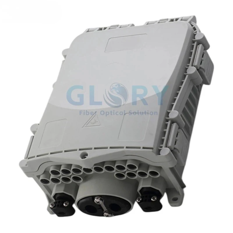
GL-8207-B Splice Enclosure
High-capacity field enclosure with hardened subscriber outputs for protected feeder-to-distribution transitions.
- 96-fiber splice capacity
- 8 preconnectorized hardened adapters
- IP68; wall, pole or aerial mounting
GL-ODB-16S Termination Enclosure
A 16-port enclosure for controlled distribution, splitter integration and service access in FTTH or MDU projects.
- Up to 16 SC adapter positions
- Supports up to 1×16 PLC splitter
- IP65, IK10; aerial, pole or wall mounting

GL-FTB-10E FAT Terminal
A compact last-mile terminal for connecting feeder fiber to hardened subscriber drops with less field termination work.
- 10 Mini SC waterproof adapter positions
- Splitter tray options including 1×2 + 1×8
- IP65; wall, pole or messenger mounting

PLC Splitter Range
Equal-split passive modules for centralized or cascaded PON designs, packaged for the selected enclosure and maintenance method.
- 1×2 through 1×64 listed range
- Bare, blockless, ABS, LGX and rack formats
- Custom pigtail, connector and polish options

Drop Core Fiber Optic Cable
A dielectric, gel-free flat drop structure for hardened drop assemblies and outdoor-to-building access routes.
- 4.5 × 7 mm listed construction
- 1–2 fibers; G.652D or G.657A options
- Available as preconnectorized assemblies

2-Core FTTH Wall Socket
A compact indoor termination and slack-management point before the final patch connection to the ONT.
- 2 × SC simplex or 2 × LC duplex
- PC + ABS, 90 × 90 × 16 mm
- Wall-mounted or desktop installation
For preconnectorized rural or rapid-rollout work, Glory can also configure plug-and-lock terminal platforms in 4F–24F, splitter or TAP versions. Connector compatibility is confirmed before the enclosure and drop-cable BOM is released.
Our configuration method
How Glory turns a rollout plan into an ODN BOM
The quotation starts with network and construction inputs, then resolves them into products, quantities and acceptance evidence.
| Project input | What Glory checks | Release output |
|---|---|---|
| PON type and optical class | OLT/ONT wavelength plan, receiver limits, connector interface and engineering margin | Approved optical-budget basis |
| Homes passed and take rate | Port utilization, spare capacity, split ratio and centralized or cascaded placement | Splitter and enclosure schedule |
| Feeder and distribution routes | Fiber count, distance, aerial or underground method, branching and restoration points | Cable and splice-closure BOM |
| Access-point locations | FAT/FDB port count, mounting, ingress rating, connector family and drop reach | Terminal and adapter configuration |
| Subscriber installation | Indoor/outdoor transition, bend performance, outlet, patch lead and ONT handoff | Drop and premises kit |
| Acceptance requirement | Identifiers, inspection, insertion loss, OTDR wavelengths, thresholds and report format | Test and labeling package |
The loss worksheet includes fiber attenuation, every splitter stage, connector pair, splice, passive device and an agreed engineering margin. Published "typical" values are not substituted for the approved project limits.
Solution models
Four common deployment models
Glory selects and configures products around the operator's density, route, labor model and restoration strategy.
Centralized Split
One principal splitter location feeds distribution fibers toward local access terminals.
- Central splitter inventory and access
- Clear port assignment
- Distribution fiber count sized to growth
Cascaded Split
Primary and secondary splitters move optical distribution closer to smaller service clusters.
- Useful for long or branched routes
- Can reduce distribution fiber demand
- Every stage included in the loss budget
Preconnectorized Quick ODN
Hardened adapters, factory-terminated drops and plug-and-lock terminals reduce field splicing at access points.
- Factory-controlled connector assemblies
- Consistent port identification
- Requires end-to-end connector compatibility
MDU Hybrid Access
Outdoor feeder hardware transitions to building FDBs, riser distribution and compact subscriber outlets.
- Building-level capacity planning
- Separate outdoor and indoor requirements
- Serviceable floor or zone terminals
Testing and delivery
Product evidence and installed-network acceptance
Factory evidence verifies supplied components before shipment; route-level commissioning confirms the installed ODN after splicing, mating and field handling.
Glory factory package
- Approved product configuration and drawing
- Splitter port and connector identification
- Insertion-loss / return-loss data where specified
- Cable length, fiber count and jacket marking
- Batch labels and packing schedule
Field acceptance plan
- Connector inspection and cleaning before mating
- Continuity and port-map verification
- End-to-end optical loss test
- OTDR trace at agreed PON wavelengths
- As-built route, splice and subscriber records
Connector end-face inspection can reference IEC 61300-3-35:2022. Installed-network test methods and thresholds should be agreed with the operator before construction begins.
Project workflow
From service-area data to tested delivery
Share Network Inputs
Service area, PON class, take rate, routes, split plan, mounting and local conditions.
Confirm Architecture
Glory maps feeder, distribution, split points, access terminals, drops and spare capacity.
Approve BOM & Sample
Review drawings, interfaces, labels, splitter data, cable construction and test format.
Produce, Test & Pack
Products are released against the approved configuration and packed by site, route or rollout phase.
Project request
Information that helps us quote the correct ODN
A partial GIS export, route sketch or subscriber table is enough to begin. Glory can identify the remaining configuration decisions before production.
Network
GPON / XGS-PON, OLT and ONT optical class, connector interface
Demand
Homes passed, initial connections, take rate and growth reserve
Topology
Centralized or cascaded split, ratios, locations and spare ports
Routes
Distances, aerial / duct / direct-buried method and branch points
Field Hardware
Mounting, IP requirement, splice or hardened interfaces and drop lengths
Acceptance
Loss thresholds, OTDR wavelengths, labels, reports and rollout quantities
Build a project-specific FTTH ODN package
Send the network plan to Glory Optical for architecture review, product mapping and a configuration-based quotation.
Frequently asked questions
Working with Glory Optical
Q: What does Glory Optical include in an FTTH ODN package?
A: A project package can include splice closures, fiber distribution boxes, preconnectorized FAT or NAP terminals, PLC splitters, feeder and drop cable, subscriber wall outlets, adapters, pigtails, labels and optical test documentation. The final BOM follows the approved topology, split plan and installation environment.
Q: Can the same passive ODN support GPON and XGS-PON?
A: It can when the passive components, wavelength range, connector performance and total optical budget meet the selected system requirements. Glory confirms splitter, fiber and connector configurations against the operator's OLT and ONT classes instead of assuming every existing ODN is automatically ready.
Q: Should an FTTH project use centralized or cascaded splitting?
A: Centralized splitting simplifies splitter control and can preserve operational visibility, while cascaded splitting may reduce distribution fiber in dispersed service areas. The correct choice depends on subscriber density, route length, port utilization, restoration strategy and the available optical-loss margin.
Q: Can Glory supply preconnectorized Quick ODN components?
A: Yes. Glory offers preconnectorized FAT terminals, hardened-adapter splice enclosures and configurable plug-and-lock terminal platforms. Connector family, port count, splitter arrangement, cable assembly and mounting method are confirmed for the project before production.
Q: What information is needed for an FTTH ODN quotation?
A: Send the PON type and optical class, homes passed and take-rate target, feeder and distribution routes, split ratios and locations, aerial or underground method, enclosure mounting conditions, drop lengths, connector preference, test criteria, labeling and rollout quantities.