Placement in the optical access network
A Compact Service Point Between Distribution Cable and Subscriber Runs
The enclosure is intended for the point where an upstream cable is secured, opened and organized before individual fibers continue through adapters, pigtails, splices or a project-selected passive splitter. It is not defined only by the number printed in the model name; cable geometry, tray allocation and connector loading must also match the site.
Upstream side
The lower area receives the main cable, provides a route toward the splice and storage zones, and keeps the feeder approach away from the subscriber-facing interface. The documented incoming-cable limit is Φ12 mm, so actual sheath diameter and strength-member construction should be checked before the entry hardware is released.
Subscriber side
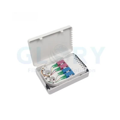
Drop fibers leave through positions sized for 2 × 3 mm cable. The visible interface can be configured around cassette-style SC or LC hardware, while a PLC module may be integrated when the optical design calls for splitting. Port quantity, polish type and the loaded state are purchasing fields, not assumptions created by the housing.
How to read "16 CORE" and "Maximum Capacity 36"
The manual names the version "16 CORE" and places the value "36" in a maximum-capacity column, but it does not assign a unit to 36. Treat neither value as an automatic adapter count, splice count or splitter output count. The approved internal drawing must show how fibers, protectors, trays and interfaces are allocated.
Service-oriented construction
How the Interior Is Divided for Installation and Later Access
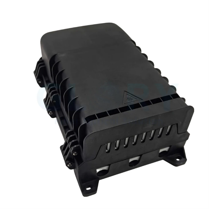
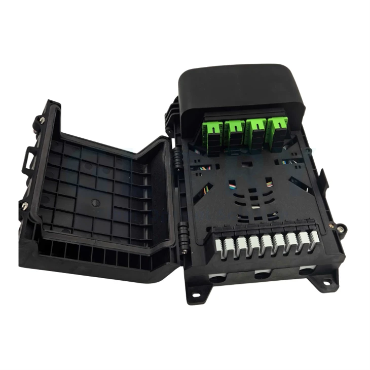
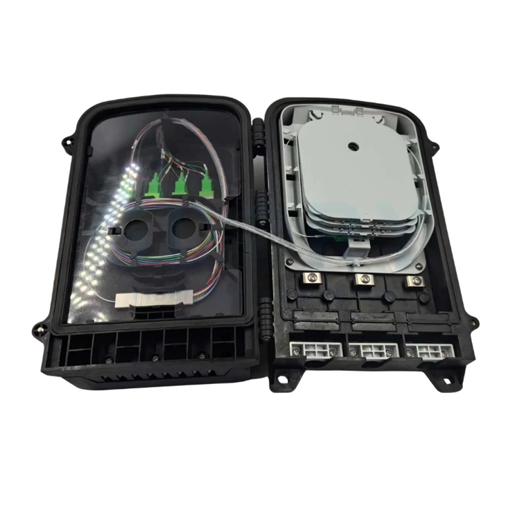
The enclosure uses a hinged cover and a movable internal deck. The resulting working zones help keep cable preparation, protected fiber storage and connector-side work from competing for the same space.
Liftable Working Deck
The distribution panel pivots upward so the cable chamber below remains reachable after the base has been mounted. Technicians can approach the feeder fixation area from the front instead of removing the enclosure or pulling an already organized tray stack away from the wall.
Three Routing Groups
Main cable, pigtails and patch cords are assigned separate paths. That physical division limits unnecessary crossings through the splice and interface zones and makes it easier to reproduce the same routing during sample approval, installation and replacement work.
Closed PP Shell
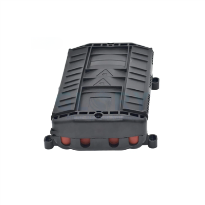
The PP housing is listed at IP65 and for −40°C to +85°C working conditions. These are defined enclosure and environmental fields; they do not establish an IK class, a flame rating, UV endurance or continuous underwater use.
Cable Geometry Is Known
A Φ12 mm maximum incoming cable and 2 × 3 mm outlet size give the engineer measurable entry limits. Cable drawings should be compared with these dimensions before a sample is loaded, especially when flat drop cable boots or non-standard sheath constructions are involved.
Mounting Is Site-Selectable
The instruction set covers wall fixing, a pole-ring arrangement and attachment to an overhead support. The enclosure stays the same, but the brackets, anchors, rings, hangers and cable supports must be selected for the actual structure.
Connector Acceptance Values
The stated interface limits are insertion loss ≤0.2 dB, UPC return loss ≥50 dB, APC return loss ≥60 dB and more than 1,000 mating cycles. These values belong to the selected connectorized interface and must not be presented as splitter loss or end-to-end link loss.


Configuration control
Build Sheet for the 16 CORE Version
Use the housing data as the fixed starting point. The optical hardware and the exact internal loading should then be frozen on one drawing and bill of materials.
Verified product data
Mechanical, Environmental and Optical Interface Values
The tables below separate housing facts from optical interface limits and from the configuration fields that still need a project decision.
Enclosure and Environment
| Field | Listed Value | Use in Project Review |
|---|---|---|
| Version | 16 CORE | Use with the approved internal layout; do not derive an adapter count from the name alone. |
| Housing material | PP | Black enclosed body shown in the supplied product photographs. |
| External dimensions | 281.4 × 177 × 101.6 mm | Check opening swing, cable approach and clearance around the mounting feet. |
| Ingress class | IP65 | Assess any impact, flame, UV or immersion requirement separately. |
| Working temperature | −40°C to +85°C | No separate installation or storage range is given. |
| Relative humidity | ≤85% at +30°C | Keep the reference temperature with the humidity value. |
| Atmospheric pressure | 70–106 kPa | Environmental value listed in the instruction manual. |
| Mounting | Wall / pole / aerial support | Order the matching hardware and support details. |
| Included items | User manual ×1; accessory bag ×1 | Ask for the accessory-bag content list for the selected mounting format. |
Model, Fixing and Cable Dimensions
| Model | Body Size A × B × C | Manual Capacity Entry | Fixing Reference | Incoming Cable | Outlet Size |
|---|---|---|---|---|---|
| 16 CORE | 281.4 × 177 × 101.6 mm | 36, unit not stated | 265 × 133 mm / 52 × 128.6 mm | Up to Φ12 mm | 2 × 3 mm |
Connectorized Interface Acceptance
| Acceptance Item | Value | Boundary |
|---|---|---|
| Insertion loss | ≤0.2 dB | For the selected connector/adapter interface, not the passive splitter. |
| UPC return loss | ≥50 dB | Use only when UPC hardware is ordered. |
| APC return loss | ≥60 dB | Use only when APC hardware is ordered; do not mate APC and UPC. |
| Mating endurance | >1,000 cycles | Apply to the loaded interface selected for the finished assembly. |
| Grounding withstand voltage | ≥3,000 V DC for 1 minute | The manual states no puncture or flashover; confirm the applicable grounding arrangement and method. |
Items That Belong on the Approved BOM
| Item | Available Direction | Project Detail Required |
|---|---|---|
| Adapter presentation | Cassette-style SC or LC | Quantity, simplex/duplex, polish, sleeve type and factory-loaded state. |
| PLC splitter | Internal integration possible | Ratio, package, operating wavelength, fiber, lead length, connectorization, worst-port loss, uniformity, PDL and directivity. |
| Main cable | Up to Φ12 mm | Construction, fiber count, measured OD, sheath, strength members and retention method. |
| Drop cable | 2 × 3 mm outlet geometry | Quantity, construction, assigned outlet, termination, length, seal and label. |
| Fiber routing | Separate routes for cable, pigtails and patch cords | Port map, splice allocation, bend-control path and slack-storage plan. |
Site-specific use
Deployment Decisions by Network Node
The same housing can serve different access locations, but the correct internal loading and mounting kit depend on where technicians will open it, how cables approach it and whether passive splitting is required.
Small Building Demarcation
At a small apartment block or business entrance, a large cabinet can occupy unnecessary wall area and make short subscriber routes harder to organize. This enclosure places cable capture, protected splices, connector presentation and stored fiber inside a 281.4 × 177 × 101.6 mm body. Fix it near the riser or exterior handoff, keeping enough space to swing the cover and raise the internal deck. The design package should state wall construction, anchors, active fibers, splice allocation, SC/LC format, polish, drop-cable route and any local fire requirement.
Splitter-Loaded PON Access Point
A housing that merely has room for a PLC module does not define the optical budget. For a GPON or XGS-PON node, load the enclosure only after the split architecture, module package and connector state have been approved. The feeder enters through the Φ12 mm-limited side, while subscriber cables use the 2 × 3 mm outlets. The order should identify the ratio, input and output leads, fiber type, wavelength, port-level loss limits, connector polish, reserve margin and whether the splitter is factory fitted or installed in the field.
Pole Node Serving a Short Drop Cluster
When several premises are reached from one telecom pole, cable orientation and support hardware matter as much as enclosure capacity. Use the documented pole-ring arrangement so the box is secured independently of the feeder and drop strain. Place the service side where the cover can open without interference from the pole or nearby cables. Prior to production, provide pole diameter, ring range, band material, mounting height, feeder route, drop direction, cable support points, grounding expectation and the exact adapter or splitter loading required for the cluster.
Aerial Spur on a Messenger Route
Transferring a wall configuration directly onto a support wire can leave the enclosure vulnerable to rotation, cable pull and restricted access. The manual shows two chassis attachment positions for overhead installation. Use them with a project-selected hanger and bolted restraint, then support feeder and service loops independently. Engineering review should cover messenger diameter, hanger spacing, wind and cable load criteria, box orientation, opening clearance, bend radius, unused-outlet sealing and the local aerial construction rules that are outside the product's IP65 declaration.
Procurement control
RFQ Data That Prevents Configuration Rework
A usable inquiry should describe the intended finished assembly, not only the empty housing. The following fields connect the physical enclosure to the optical design and the installation package.
| RFQ Field | Information to Send | Why It Matters |
|---|---|---|
| Node function | Building handoff, pole branch, aerial point or other defined location | Determines mounting, orientation, access and cable-support needs. |
| Fiber allocation | Working fibers, reserves, splice count, tray assignment and port map | Prevents "16 CORE" or "36" from being interpreted as the wrong capacity type. |
| Connector hardware | SC/LC, simplex/duplex, UPC/APC, quantity, pigtails and labels | Controls the visible interface and its optical acceptance values. |
| PLC assembly | Ratio, package, leads, fiber, wavelength, connectors and test limits | Separates splitter performance from the enclosure's connector values. |
| Incoming cable | Drawing, construction, fiber count, actual OD and strength members | Confirms fit within the Φ12 mm boundary and the correct retention parts. |
| Drop cables | 2 × 3 mm profile confirmation, quantity, length, termination and outlet assignment | Controls sealing, routing and numbering on the subscriber side. |
| Mounting kit | Wall anchors, pole-ring details or overhead hanger specification | Ensures the hardware arrives for the actual support structure. |
| Acceptance package | Drawing revision, sample approval, optical report, inspection fields, labels and packing | Creates a repeatable reference for batch and repeat orders. |
Suggested line-item description
16 CORE FTTx fiber access termination box, black PP housing, IP65, 281.4 × 177 × 101.6 mm, incoming cable [construction / OD, maximum Φ12 mm], 2 × 3 mm drop cables [quantity / length / outlet map], interface [SC or LC / simplex or duplex / UPC or APC], PLC [none or full specification], mounting [wall / pole / aerial], hardware [ ], labels [ ], optical acceptance [ ] and packing documents [ ].
Supplier and project support
How Glory Optical Supports a Loaded Termination-Box Assembly
Ningbo Glory Optical Communication was founded in 2008. The company lists a 20,000 m² facility, more than 300 passive optical products, supply to over 50 countries and OEM/ODM capability for passive fiber infrastructure.
Housing and Internal Parts
Injection molding and enclosure assembly can be linked to one controlled housing revision, including the cover, base, movable deck, trays, cable-fixing parts and mounting points used for this 16 CORE configuration.
Optical Component Loading
Adapter, pigtail and PLC integration can be specified as a finished BOM. The order should state the exact components and measurements rather than relying on a family-level description of the box.
Drawing and Sample Review
A drawing and physical sample give the buyer a practical way to inspect cable fit, panel movement, routing, port numbering, connector mating and the chosen mounting accessories before volume supply.
Repeat-Order Identification
Product labels, port labels, cable tags, lot references, carton marks and document revisions can be tied to the approved BOM so later orders reproduce the same loaded configuration.
Prepare the finished assembly
Send the Physical Cable Data and the Optical Build Sheet Together
For a configuration review, provide the incoming-cable drawing, drop profile, fiber allocation, splice plan, connector format, polish, PLC specification, mounting structure, port numbering, acceptance data and packing instructions.

Our Quality Promise
Comprehensive 3-Year Warranty
We confidently back all our products with a 3-year warranty. Our specific service policy is: within one year for quality issues, we take full responsibility for returns; within two years, for replacements; and within three years, for repairs.
Clear & Competitive MOQ
We welcome both trial and bulk orders. Our standard Minimum Order Quantity (MOQ) is 50 units. We also offer free samples for testing to help you evaluate our quality with confidence.
Fast & Reliable Logistics
We guarantee delivery within 10 days for standard items. Our logistics advantage includes cost-effective door-to-door service to simplify shipping for you.
Our Foundation
Backed by 18 years of experience since 2008, we control quality from our own factory, accept OEM/ODM requests, and maintain ready stock for wholesale. We focus on delivering the optimal balance of price and quality directly to end customers worldwide.
Your trust is our priority. Partner with us for dependable fiber optic solutions supported by clear promises.
Hot Tags: 16-core fttx fiber optic termination box, China 16-core fttx fiber optic termination box manufacturers, suppliers, factory, 24 Port Fiber Termination Box, box fiber, fiber distribution box outdoor, fiber optic box outdoor, fiber splicing box, Optical Fiber Distribution Box