
Picture two sites about to receive upgraded equipment. The cable between them has carried traffic for nearly 30 years, and one splice closure on the route was opened during an emergency repair. The network engineer needs to know whether the repaired point still shows a problem. The buyer needs to know whether to ask for a price on one repaired splice or on replacing the length between two splice points. The rest of this article follows that route.
What Determines Whether an Installed Cable Can Stay in Service?
The question "can this cable stay?" splits into three smaller questions. Each one is answered with different evidence, and that evidence usually comes from different people on the project.
| What is being judged | What to check | Evidence to collect |
|---|---|---|
| Glass fibre transmission | Whether any section shows unusual attenuation, and how much optical power the whole link loses at the working wavelength. Section attenuation is reported in dB/km; end-to-end loss is reported in dB. | Test trace for each fibre, test wavelength, end-to-end insertion loss |
| Cable body and splice hardware | Visible sheath damage, sustained crushing, tight bends, and the state of splice closures. Optical loss that passes today can sit beside mechanical damage that still needs attention. | Inspection photos, route position, closure ID, construction and repair records |
| Compatibility with the target service | Fibre type, distance, operating wavelength, and channel-loss ceiling of the optics going in. A link that works today can still miss a new equipment specification. | Target equipment datasheet, actual link length, engineering margin the project requires |
Fibre type deserves its own check on older routes. The FOA notes that once speeds pass 10 Gb/s and distances exceed 20 km, singlemode outside plant fibre is worth characterising for chromatic dispersion, polarisation mode dispersion, and spectral attenuation, especially on older cable plant built to earlier standards. ITU-T G.Sup.59 adds that the permanent type of hydrogen damage is most apparent in older G.652.B fibre, which is one reason to confirm the fibre category before promising full-spectrum use.
The installation year answers none of these three questions on its own. It does tell the team where to look for the original cable type, the route drawings, and the acceptance records. (ITU-T G.Sup.59 · FOA)
What Does "More Than 30 Years" Mean for Optical Fiber?
The 30-year figure comes from the attenuation-stability clause of ITU-T Supplement G.Sup.59 (02/2018), which states that the expected lifetime of optical fibres is typically more than 30 years. Both words matter. The statement concerns glass fibre, and it describes a typical value, not a guarantee for any single route. The Supplement itself calls much of its material speculative, while reporting that significant spontaneous fibre breakage in fibres used for decades is not known. Sheaths, splice closures, and every past repair carry their own service histories, and external damage such as excavation or flooding lies outside the Supplement's scope. (G.Sup.59 §6, §7.4)
The Supplement also gives a time scale for attenuation. It draws on more than four decades of field experience, since optical cables entered commercial service in 1977, and it assumes that any degradation grows linearly with time. On that basis, apart from hydrogen effects, new degradation adding more than a few hundredths of a dB per kilometre over the life of the cable is considered unlikely. Read over the life of the cable as a lifetime total, because it is not a yearly rate. Hydrogen is the stated exception. The reversible type matters mainly for underwater cable, and the permanent type is most apparent in G.652.B fibre, which the full-spectrum G.652 specification of 2001 was written to address. (G.Sup.59 §7.2, §7.4)
Field verification stays necessary for a simple reason. Accelerated ageing is usually run at raised temperature and humidity, and the Supplement cautions that high-temperature mechanisms can be triggered which would never occur in service, producing an unrealistically short lifetime estimate. The 30-year value and laboratory ageing figures therefore describe fibre populations and say nothing direct about one route with a repaired closure. For that closure, the most specific evidence is the repair record plus a test trace that can be compared with an earlier one. (G.Sup.59 §7.4)
How to Test an Existing Fiber Link Before an Upgrade
The three steps below follow the order in which evidence usually becomes available on site.
3.1 Find the baseline or establish one today
Confirm both end sites, the cable section number, the fibre number, and the test direction. Then look for the as-built acceptance trace, a later inspection trace, or a post-repair trace. A valid comparison uses the same fibre, wavelength, and direction, with the same or similar pulse width and range. The FOA guide puts heavy weight on documentation: where the cables go, how long they are, and what they tested at for loss. If no acceptance data survives, label today's measurement the first traceable baseline and archive its date, settings, and raw file. That settles whether the link meets the service requirement now. How much it has changed since installation stays unknown. (FOA testing guide)
3.2 Read the shape of the OTDR trace
A two-panel schematic helps here. Both panels use the same axes, with distance along the fibre on the horizontal axis and relative backscatter level on the vertical axis, and each panel answers a different question.

Illustrative schematic prepared for this article, not measured data. Panel B follows the concept in NTT East's published field example.
| Panel | What it shows | What the caption should explain |
|---|---|---|
| A. Earlier vs current, same wavelength | Two comparable traces from one fibre, overlaid, with splice steps at known points and one section where the current trace falls more steeply. | A step marks a single location, while a change in slope covers a stretch of cable. Record the test direction so the anomaly maps to the route. |
| B. Same section, different wavelengths | Traces at 1550 nm and 1650 nm, with the longer wavelength falling more steeply over one section. | NTT East's field example reports such a section and infers stress-induced bending there. Follow-up inspection looks for the source of stress along that stretch. |
Panel A asks when the change began, and Panel B asks whether the anomaly depends on wavelength. NTT East adds that a normal glass fibre shows its lowest loss near 1550 nm, while bending makes loss climb as wavelength increases, so a multi-wavelength comparison helps estimate what kind of loss is present. Its authors also cite earlier studies indicating that such stress tends to grow with sudden environmental events and with cable ageing. (NTT East, NTT Technical Review, Apr. 2022)
3.3 Measure end-to-end loss and calculate the margin
Use a light source and power meter, or an OLTS, for the acceptance figure. The FOA explains that standards call for insertion-loss testing this way because the source and meter copy the transmitter and receiver of the real link, while an OTDR infers loss from backscatter. Record which reference method you used (one, two, or three reference cables), since each gives a different result for the same cable. Singlemode links are commonly tested at 1310 nm and optionally 1550 nm, and the test wavelength should match the service. Then compare the measured value with the allowable channel loss of the target service. (FOA insertion-loss testing)
| Item (hypothetical figures) | Value |
|---|---|
| Allowable channel loss, target service | 8.0 dB |
| Measured end-to-end insertion loss | 6.2 dB |
| Remaining margin | 1.8 dB |
| Engineering margin the project requires | 2.0 dB |
| Shortfall | 0.2 dB |
On these assumed figures the link fits inside the equipment's loss ceiling and still falls 0.2 dB short of the project's margin. That gap is why a link that works and an upgrade that can be signed off may get different answers.
Research sidebar: what a study of 22 installed cables can tell us
Rowaished and co-authors used an OTDR, mainly at 1310 nm, on vacant fibres in 22 live backbone cables of varying age in Saudi Arabia's Eastern Region. They report span-attenuation deviations of about 2% to 30% on some older links, overall cable-loss deviations of 2% to 20%, and no correlation for splice loss. Their reference values were the manufacturer's attenuation specification and a calculated loss budget built from FOA-recommended figures (0.4 dB/km at 1310 nm, 0.15 dB per splice, 0.5 dB per connector).
The authors also point out that splice histories on live cables were poorly documented, and that repairs sometimes spliced in other fibre types such as G.652C or G.656. The percentages therefore describe deviation from this study's own reference values under uneven documentation, and they give no yearly ageing rate for any one fibre. Some cables exceeded the 25-year lifespan the authors cite from manufacturers. For readers the practical point is simple: after each repair, save a dated measured trace so the next test can compare the same fibre. (Rowaished et al., IJSET 13(4), 2025)
When to Reuse, Repair, or Replace a Cable Section
Start with the decision table, then read the notes beneath it. A reader should be able to move from the evidence in hand to the next piece of work to approve.
| Decision | When it applies | Engineering action and acceptance basis |
|---|---|---|
| Reuse | The cable body is in acceptable condition and present performance meets requirements. If an upgrade is planned, fibre type, distance, and measured loss also meet the target service with the margin required. | Name the fibres and services approved for reuse and file today's data. Record what should trigger a retest, such as reopening a closure or construction along the route. |
| Repair a point | The anomaly can be located, its cause is accessible, and loss and margin are expected to meet requirements after repair. | State the work location and extent, such as relieving a local squeeze or redoing a confirmed bad splice. Retest the event and the whole link after repair, then accept against the target service. |
| Replace a section | Damage is spread over a distance, local work cannot restore mechanical integrity, or the link is expected to stay short of the target even after repair. | Define the candidate section between identifiable end points, estimate the loss of the new cable plus the new splices at both ends, confirm the replacement removes the limiting factor, then fix the scope of work. |
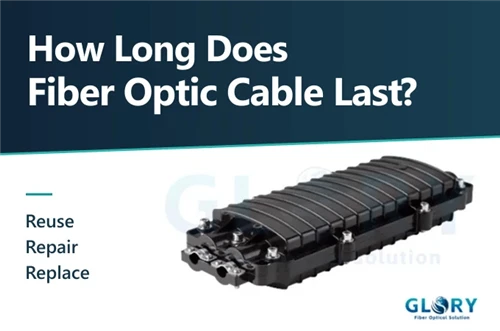
When the trace points to a particular closure, the repair decision depends on what is inside it. G.Sup.59 notes that fibre in splice enclosures can come into direct contact with moisture, and that the strength of coated fibre does not reliably predict its strength once the coating is stripped. Permanent stress on the stripped section should therefore be kept low. Reopening a closure calls for a look at tray layout, fibre storage loops, and splice condition, and the work order should say which of those will be touched. If the job includes swapping the closure itself, Glory's article on dome versus inline closures covers how FTTH procurement engineers weigh the two formats. (G.Sup.59 §8.1)
A second judgement changes the purchase scope. If the upgrade is limited by fibre type or distance across the whole route, replacing a short section may leave the outcome unchanged, so recalculate the link before approving it. Network position matters too. Appendix II of G.Sup.59 shows how the number of users per fibre and the urgency of repair change with where a cable sits, from one customer on a building fibre to hundreds of users on a trunk. Operators can reasonably set a stricter acceptance threshold on routes where one fibre serves many users.
Cause also bears on the choice between repair and replacement. G.Sup.59 observes that mechanical failure in the cabled part of a fibre is rare without an outside mechanism such as a falling tree or an accidental dig-up. When a section shows sustained damage, ask what acted on it and whether that source is still present. A squeeze that came from one past excavation can be relieved at a point, while ongoing construction beside the route may undo a local repair. Where the decision is repair, the FOA advises keeping spare cable, mechanical splices, and good documentation on hand for restoration, which shortens the next outage as well. (G.Sup.59 §8.1 · FOA)
Back to the opening case. The same anomaly can be located, repaired, and retested with enough margin left, and those three conditions together support a local repair. If the post-repair retest still leaves the link short, return to the route and redraw the work area.
What to Include in a Fiber Repair or Replacement Request
Give procurement a field table that converts straight into an RFQ attachment. Every loss value should state what was measured, in which unit, and at which wavelength, so a contractor can tell a single-event loss from the end-to-end acceptance value.
| Group | Suggested fields |
|---|---|
| Asset and scope | Cable section number, A/B ends, fibre numbers, fibre type, length, start and end points of the section to be treated |
| Test and location | Date, wavelength, direction, instrument and key settings, event distance from the test end, matching closure or handhole ID |
| Loss and margin | Event loss (dB), section attenuation (dB/km), end-to-end insertion loss (dB), allowable loss for the target service, remaining margin, margin the project requires |
| History and delivery | Whether an as-built baseline exists, earlier repair dates and work, site photos, raw OTDR files, retest results required after the repair |
Close the request with one concrete instruction: ask the contractor to quote by the named cable section and fibre numbers, list the new splice points they expect to add, and deliver the post-repair event trace and end-to-end loss result. Procurement can then compare what each quote covers, and operations knows what will be checked at handover.
Two further lines make the acceptance data comparable between contractors. Ask for OTDR traces taken with a launch cable long enough to clear the instrument's dead zone, which lets the first connector on the cable be assessed. Ask also that the loss report name the reference method used (one, two, or three reference cables), because the FOA notes that the choice changes the reported value for the same cable. (FOA testing guide)
Can This Cable Carry the Next Service?
Return to the route that has run for nearly 30 years. Write the decision as a sentence that can go straight into an engineering assessment:
At [wavelength], the measured end-to-end loss on this fibre is ___ dB and the remaining margin for the target service is ___ dB. Based on the mechanical inspection of the ___ section, we recommend ___, with acceptance or retest conditions of ___.
A decision in this form can be signed, quoted against, and rechecked the next time the route is touched.
Sources
- ITU-T, Supplement 59 to G-series Recommendations: Guidance on optical fibre and cable reliability (02/2018), §6, §7.2, §7.4, §8.1, Appendix II.
- Fiber Optic Association, Fiber Optic Testing, FOA Reference Guide to Fiber Optics.
- Technical Assistance and Support Center, NTT EAST, Development of Loss-evaluation Tool for Efficient Characterization of Optical Fiber Cables, NTT Technical Review, Vol. 20, No. 4, Apr. 2022.
- A. J. Rowaished et al., Effect of Time on Fiber Optic Cable Characteristics, International Journal of Science, Engineering and Technology, 13(4), 2025.