
A practical retrofit path for central offices that have space and power freed by copper retirement and want to add edge equipment without disturbing live service.
When a copper network is switched off, the racks, floor space and power feeds it leaves behind start to look useful for something else. In a November 2026 column for Lightwave, Gary Bolton, CEO of the Fiber Broadband Association, argues that AI inference will move out of large centralized facilities and into local ones, and that existing telco central offices are a natural home for it because they already have space and power built for legacy copper networks (Lightwave, "Society's four fiber transitions"). That is Bolton's forecast, and each site still needs its own assessment of power, cooling and floor loading.
This article covers the passive fiber layer only. The question is a practical one: if the central office is still carrying live services, how do you connect the first edge racks to fiber and leave room for the next ones? It is written for network planners, system integrators and procurement engineers who have to turn a retrofit idea into a bill of materials.
- Audit the existing fiber and the new equipment first, and record every link in one port-and-link table.
- Use that table to decide where existing ODF ports can be reused and where new panels, cords or trunks are needed.
- Connect the first racks with duplex LC; add MPO/MTP trunks in a second phase when many links share a route.
- Agree test items, handover documents and a rollback path before the cutover window.
1. Why Fiber Matters After Copper Retirement
Bolton's column groups four shifts around fiber. Copper is giving way to fiber, which he describes as more reliable and far less power-hungry. Broadband is reaching more households. The economy is moving toward AI, which he expects to be increasingly distributed, with inference running closer to users. And quantum technologies, from key distribution to sensing, are expected to ride on the same glass.
For a cabling buyer, two of those threads touch the next purchase order: the space and power that copper retirement frees, and the shift of compute toward the network edge. The rest is useful background for why the fiber plant deserves investment.
Treating a central office as a small data center is an older idea than the current AI discussion. The Open Networking Foundation's CORD project (Central Office Re-architected as a Datacenter) described commodity servers connected through a spine-leaf switch fabric at the network edge. Spine-leaf fabrics typically need many more short rack-to-rack links than a legacy exchange had, which is why the cabling plan, and not only the equipment list, decides how smoothly the first racks go in.
2. Audit the Existing Fiber Before Ordering New Cabling
Ordering starts with two inventories: what the building already has, and what the new equipment needs.
Inventory the current plant
For every ODF port, record the in-service circuit, the spare fibers, the fiber type, the connector type and its end-face type (UPC or APC), and the last test result if one exists. APC and UPC connectors should not be mated to each other, so the polish of every reused port matters as much as its connector style.
Check the new equipment
Get the switch and optical module list. For each module, note the optical interface (duplex LC, MPO-12, MPO-16 or another), the link distance, the allowed channel loss and the number of ports needed in the first phase. Glory's own configuration method follows the same logic: the transceiver interface selects the cable, and speed alone does not (Glory data center fiber cabling solution). Parallel single-mode optics such as DR4 variants commonly use multi-fiber MPO interfaces, and some specify angled polish, so read the module datasheet before assuming an existing duplex LC link can be reused.
Produce one port-and-link table
Give each link a start port, an end port, a decision to reuse or build new, the test requirement and a cutover batch. The table below shows the format with placeholder identifiers.
| Link | From | To | Fiber / interface | Reuse or new | Test | Batch |
|---|---|---|---|---|---|---|
| L-001 | ODF-A, ports 01/02 | Edge rack 1, switch port 1 | OS2, duplex LC | Reuse spare pair after clean and test | OLTS | 1 |
| L-002 | ODF-A, ports 03/04 | Edge rack 1, switch port 2 | OS2, duplex LC | Reuse spare pair after clean and test | OLTS | 1 |
| L-010 | New patch zone | Edge rack 2, cassette panel | OS2, MPO trunk to LC cassette | New | OLTS, plus OTDR if specified | 2 |
This table becomes the purchasing source. Every row marked "new" turns into a line on the bill of materials, and every row marked "reuse" turns into a test task. Glory asks for the same inputs when it quotes a cabling package: the switch and transceiver list, port count, rack or panel layout, route lengths, fiber type, connector interfaces and the documentation required (see the solution page), so the table can go straight into a quotation request.
3. Match Glory Products to Each Part of the Link
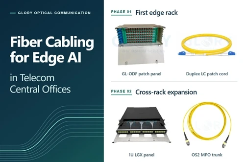
The four examples below match each retrofit position to a Glory product and identify what to check before ordering.

When new cable has to be terminated, spliced and cross-connected, choose the configuration by cable entry, fiber count, adapter type and rack space. The listed models run from GL-ODF-12 in 1U up to GL-ODF-144 in 8U, with side cable entry and front-side operation. Confirm the loaded fiber count and adapter format in the approved bill of materials.

If the module and the patching port are both matching duplex LC interfaces, the first racks can be connected from the existing patching area. Choose OS2 or multimode (OM3/OM4) to suit the module and link. OS2 cords are offered in UPC or APC, so match the polish to the panel and the module.

When several links share one route between racks, choose the trunk by interface, fiber count, polarity, connector gender and loss budget. Glory's MPO/MTP range includes 12- and 24-fiber trunks and MPO-to-LC breakouts in single-mode and multimode versions.

When the trunk is MPO/MTP and the equipment needs duplex LC, choose a matching cassette. The listed 1U panel carries four 24-fiber cassettes (96 fibers) in one sliding tray, with MTP in and LC or SC out. Count the cassette and each added connection in the link budget.
Every cassette and mated pair adds loss. Add them to the link budget before choosing a trunk grade, and define connector gender and polarity for the whole channel, not for each cable alone. Glory's solution page makes the same point for cassettes, where the conversion loss belongs inside the channel budget.
4. Show a Two-Phase Retrofit
A phased layout keeps the first cutover small and gives later racks a defined path. The diagrams below are illustrative layouts for explaining the sequence.
Phase 1: connect the first edge racks
From the ODF inventory, pick the spare fibers, confirm port numbers and loss, then connect equipment that uses duplex LC interfaces. A handful of links does not justify extra hardware. Duplex cords from the existing patching area keep the number of connection points low and leave loss headroom.

Illustrative layout, not a project drawing. T1 marks the Phase 1 test point.
Phase 2: add racks and links
When more racks arrive and many links share the same pathway, a pre-terminated MPO/MTP trunk between racks becomes worth its connection points. Where the equipment side needs duplex LC, a modular cassette panel converts the trunk. Mark the existing patching zone, the new patching zone and the test points of both phases on the drawing.

Illustrative layout, not a project drawing. T2 marks the Phase 2 test points; T1 from Phase 1 stays on the Edge rack 1 link.
5. Specify Testing and Handover Before Cutover
Write the acceptance items into the order, not into the cutover plan the night before. A handover package for each phase should cover:
- Port mapping: every link matched to its record in the port-and-link table.
- Polarity: confirmed on every duplex and multi-fiber link.
- End-to-end insertion loss: measured on the installed link and compared with the loss budget.
- Cable labels: identical at both ends and matching the records.
- As-built drawings: updated to show what was installed, including both phases' test points.
Fluke Networks' OLTS and OTDR testing guide describes how the two instruments divide the work. An optical loss test set (OLTS) measures total insertion loss and corresponds to Tier 1 testing in TIA and ISO standards. An OTDR characterizes individual splices and connectors and is the Tier 2, or extended, step. The guide notes that an OTDR is required when the project specification says so, and recommended otherwise. It also suggests running the OTDR before the final OLTS test so faults can be fixed during installation. For short-reach single-mode optics such as the DR4 variants, allowed insertion loss depends on connector reflectance as well, which an OTDR can report. The same guide cites splice limits around 0.3 dB and connector limits that follow the manufacturer's specification, typically 0.2 to 0.5 dB. Use the limits in your own project specification where they differ.
Clean and inspect every end face before testing, including new connectors and factory-terminated cords. Glory's data center solution page points to IEC 61300-3-35 for end-face inspection criteria and notes that factory reports verify the supplied assembly before shipment, while installed-channel testing is still needed after transport, routing and mating.
Before the window opens, agree the verification items and a rollback path. Keep the original patching record for every moved circuit, label the spare ports, and re-patch to the original port if a verification item fails. Test dark fibers only unless the operator has approved a procedure for in-service ones, and never look into an unterminated fiber.
Send Glory Optical your rack layout, transceiver list, and port counts for a project-specific fiber cabling bill of materials.
Request a QuoteSources and further reading
- Gary Bolton, Society's four fiber transitions, Lightwave, November 12, 2026.
- Open Networking Foundation, CORD: Central Office Re-architected as a Datacenter.
- Fluke Networks, OLTS & OTDR: A Complete Testing Strategy (white paper).
- Glory Optical, Data Center Fiber Cabling Solution.
- Glory Optical product pages: GL-ODF patch panel, LC–LC duplex patch cord, MTP/MPO range, 1U LGX patch panel.