

High-Density Cabling
Glory Optical supplies configurable LC and MTP/MPO connectivity for server rooms, enterprise data centers, colocation facilities and high-density interconnects. Our scope covers pre-terminated trunks, breakout assemblies, modular patch panels, cassettes, rack-mount ODFs and project-specific test documentation.
Glory Optical solution scope
One passive cabling package, configured around your equipment
Instead of quoting isolated cable part numbers, we organize the trunk, transition, patching and documentation layers as one project BOM.
Pre-Terminated Trunks
MTP/MPO and LC assemblies in project-specific fiber type, count, length, jacket, polish, gender and polarity.
High-Density Patching
Modular 1U/2U/4U patch panels, MPO adapters, LC or CS interfaces, cassettes and cable management.
Equipment Transitions
MPO-to-LC breakout and harness options for switch ports, duplex equipment and staged migration projects.
Configured Evidence
Part-number control, lane-map confirmation, factory optical tests, labeling and batch-level documentation.
Our configuration rule: the transceiver interface and optical PMD select the cable-not speed alone. Send the module part number when possible so the connector, active fibers, polish and polarity can be checked before production.
Core product portfolio
Glory products for each layer of the fiber channel
Use these as building blocks. We finalize the connector and cable configuration against your port map, rack layout and acceptance requirements.
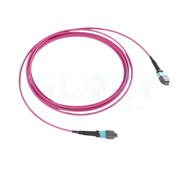
MPO Fiber Patch Cord
Factory-terminated MTP/MPO connectivity for direct equipment links, backbone trunks and MPO patching positions.
- Custom length and jacket
- Singlemode or multimode options
- Project-defined gender and polarity

MPO to LC Fiber Cable
A configurable harness for connecting multi-fiber trunks or transceivers to LC-based equipment and patching.
- 4 or 6 LC duplex legs on listed models
- OS2 and multimode configurations
- Custom polish, leg length and labeling

GL-MP6 Modular Patch Panel
A pull-out 1U/2U/4U platform with MTP/MPO, LC and CS configuration options for structured data center cabling.
- Front and rear cable management
- Up to 144F LC or 216F CS in listed 1U configurations
- Direct MPO and cassette options

1U ODF 19-Inch Rack
A compact enclosure for four removable MPO/MTP cassettes and up to 96 fibers through LC duplex couplers on the listed model.
- Standard 19-inch mounting
- Adjustable brackets
- Blank protection for unused positions
Review the MTP/MPO cable options and fiber patch panel options above, or continue to the project request checklist for a configuration-based quotation.
Our configuration method
How Glory turns project inputs into a production BOM
Every released item should connect back to an equipment interface, route or operating requirement.
| Project input | What Glory checks | What we configure | Release output |
|---|---|---|---|
| Switch and transceiver list | PMD, reach, receptacle, active lanes and breakout mode | LC, CS, MPO-12, MPO-16 or dual-interface assembly | Interface and lane-map record |
| Rack and route schedule | Link length, pathway, panel locations and service loops | Trunk length, cable construction, jacket and pulling protection | Cable schedule and labels |
| Port count and migration plan | Current ports, spare capacity and future transition points | Panel RU, cassette count, adapter type and front-port density | Panel and cassette BOM |
| Performance requirement | Maximum channel loss, connection count and planned margin | Standard or low-loss assembly grade and allowed patching model | Loss-budget worksheet |
| Handover requirement | Report format, identifiers and inspection criteria | Factory test fields, label template and batch traceability | Approved documentation package |
For example, 800G modules can use MPO-16, dual MPO-12 or duplex-style interfaces depending on the module. Glory therefore matches the quoted cable to the selected optical interface rather than labeling one connector as the universal "800G cable." See this 800G OSFP interface example.
Solution models
Three common ways we assemble the channel
We select the model according to connection loss, access requirements and expected moves, adds and changes.
Direct Equipment Connection
Factory-terminated MPO or LC assemblies connect compatible equipment interfaces with minimal intermediate hardware.
- Useful where the route is stable
- Preserves loss headroom
- Custom length and labeling
MPO Trunk + Adapter Panel
Pre-terminated trunks terminate in accessible rack panels while retaining the multi-fiber interface.
- Organized rack-to-rack routing
- Supports high port density
- Requires controlled polarity and gender
MPO Trunk + LC/CS Cassette
Modular cassettes transition the backbone to duplex or VSFF equipment-side patching.
- Front-access reconfiguration
- Practical for staged migration
- Conversion loss included in the channel budget
Testing and delivery
What can be included with the finished assembly
Testing and documentation fields are agreed before production so the delivered evidence matches the project acceptance plan.
Product configuration
- Approved connector, fiber and cable construction
- Polish, key orientation and pinned/unpinned ends
- Polarity or full lane-map confirmation
- Length, breakout legs and jacket marking
- Project label and packaging requirements
Factory evidence
- Per-fiber insertion-loss results
- Return-loss results where applicable
- Continuity, length and polarity verification
- End-face inspection record when specified
- Batch identification and report traceability
End-face inspection requirements can reference IEC 61300-3-35:2022. Installed-channel testing remains necessary after transport, routing and connector mating; factory reports verify the supplied assembly before shipment.
Project workflow
From equipment list to tested delivery
1 · Share Inputs
Equipment, transceivers, ports, rack layout, distances and documentation needs.
2 · Confirm Configuration
Glory maps interfaces, fiber, polarity, panels, labels and required performance.
3 · Approve Sample or Drawing
Review the configuration sheet, lane map, label and test-report format.
4 · Produce and Test
Assemblies are manufactured, tested, packed and released against the approved project fields.
Project request
Information that helps us quote the correct configuration
Even a partial equipment list is useful. We can identify the missing decisions before the production BOM is finalized.
Equipment
Switch, NIC, optical module and port count
Connections
LC, CS, MTP/MPO, breakout and patching plan
Routes
Rack locations, link lengths and pathway constraints
Fiber
OS2, OM4 or OM5 and required fiber count
Construction
Jacket rating, cable OD, pulling eye and breakout protection
Evidence
Loss limits, inspection, labels and report format
Build a project-specific cabling package
Send the port list and layout to Glory Optical for product mapping, configuration review and quotation.
Frequently asked questions
Working with Glory Optical
Q: What does Glory Optical include in a data center fiber cabling package?
A: A project package can include MTP/MPO trunks, MPO-to-LC breakout assemblies, LC or CS patching, modular patch panels, cassettes, rack-mount ODFs, labels and factory test documentation. The final combination follows the approved port map and transceiver interfaces.
Q: Can Glory Optical customize MTP/MPO and LC cable assemblies?
A: Yes. Available project fields include fiber type, fiber count, connector interface, polish, pinned or unpinned ends, polarity, cable length, jacket, color, breakout leg length and labeling. Configuration is confirmed before production.
Q: Which data rates can the Glory cabling range support?
A: The product range can be configured for 10G through 800G applications, but speed alone does not select the cable. Glory maps the exact optical module, PMD, reach, active fibers and receptacle to the passive cabling BOM.
Q: What factory test evidence can be specified?
A: Projects can request per-fiber insertion loss and return loss where applicable, polarity and lane-map verification, continuity, length, end-face inspection records, product labels and batch traceability. Required report fields should be agreed before production.
Q: What information should be sent for a Glory data center cabling quotation?
A: Send the switch and transceiver list, port count, rack or panel layout, route lengths, preferred fiber type, connector interfaces, breakout requirements, jacket rating, labeling scheme and required test documentation. Glory can then return a configuration-based quotation instead of a generic cable price.