


As FTTH and PON networks scale, optical splitter selection should be handled in two stages. First choose the splitting technology-FBT or PLC-according to ratio, wavelength plan, and loss budget. Then choose the PLC package-bare fiber, blockless, ABS box, cassette, or rack format-according to how the component will be protected, connected, and maintained.
Common questions include:
- When is an FBT coupler more suitable than a PLC splitter?
- Which technology is better suited to equal-split GPON, EPON, or XGS-PON distribution?
- How does splitting ratio affect the optical link budget?
- Which PLC package-bare fiber, blockless, ABS box, or cassette-fits the enclosure and maintenance model?
This guide keeps technology and packaging as separate decisions, then connects each choice to Glory Optical products, test data, and related ODN planning resources.
FBT vs PLC Splitters: Start With the Splitting Technology
FBT couplers and PLC splitters are two manufacturing technologies. Bare fiber, blockless, ABS box, LGX, cassette, and rack-mount products are packaging formats used after the PLC splitting circuit has been made.
FBT splitter/coupler: two or more fibers are fused and tapered to create a coupling region. FBT is useful for low port counts and for unequal ratios such as 5/95, 10/90, 20/80, or 30/70, where a small portion of optical power is tapped for monitoring, sensing, or a secondary branch.
PLC splitter: a planar waveguide circuit divides optical power through lithographically defined branches. PLC is commonly selected for broadband, equal-split 1×N and 2×N PON distribution, especially where higher port counts and controlled port-to-port variation are required.
The comparison should be made using measurable specifications-not a blanket assumption that one technology is always better. ITU-T G.671 defines transmission parameters for optical components and subsystems, including insertion loss, wavelength dependence, polarization dependence, return loss, and directivity. The PON link itself must also close within the relevant optical budget defined by the system standard.
FBT vs PLC Splitter Comparison Table
| Selection Factor | FBT Splitter / Coupler | PLC Splitter |
|---|---|---|
| Manufacturing method | Fused and tapered optical fibers | Planar waveguide circuit on a substrate |
| Best-known strength | Low-count and unequal power ratios | Broadband equal splitting at medium and high port counts |
| Typical configurations | 1×2, 2×2, low-count taps; higher counts may use cascaded couplers | 1×2 through 1×64 and 2×N configurations |
| Split ratio behavior | Can be symmetric or asymmetric, such as 10/90 or 30/70 | Usually specified as equal-split 1×N or 2×N devices |
| Wavelength behavior | Designed around specified operating windows; verify the exact device datasheet | Broadband PLC products are commonly specified across 1260–1650 nm; verify IL, WDL, and PDL across the required PON wavelengths |
| Port-to-port performance | Variation generally becomes harder to control as cascaded split count increases | Designed for controlled uniformity, but individual ports still vary and must be checked against the factory test report |
| Typical use | Monitoring taps, sensors, CATV or low-count custom ratios | FTTH, GPON, EPON, XGS-PON, splitter modules, FDBs, and central-office frames |
Use the loss budget and wavelength plan first. Port count alone is not a complete selection rule, and FBT remains valuable where an unequal split is required.
PLC Packaging Options: Bare Fiber, Blockless, ABS Box, and Cassette
Once PLC technology has been selected, packaging becomes a separate mechanical and installation decision. The same underlying PLC circuit can be supplied in multiple formats.
| PLC Package | Physical Form | Best Fit | Important RFQ Detail |
|---|---|---|---|
| Bare fiber PLC | PLC assembly with 250 µm fibers and minimal secondary protection | Factory integration where the customer provides the tray, tube, and strain relief | Fiber type, fiber length, routing protection, and integration dimensions |
| Blockless / mini-module PLC | Compact protected module, commonly with 900 µm pigtails | FDBs, cassettes, wall boxes, and OEM assemblies requiring a small footprint | Module dimensions, pigtail diameter, pigtail length, and connector option |
| ABS box PLC | PLC assembly inside an ABS enclosure with 2.0 or 3.0 mm leads | Standalone installation or larger distribution boxes where handling protection is important | It may be supplied unconnectorized or connectorized; specify both ends explicitly |
| LGX / plug-in cassette | Connectorized module with panel adapters | Central offices, cabinets, and modular FDBs requiring quick replacement and port access | Adapter type, polish, panel footprint, and the added mated-pair loss |
| Rack-mount tray | High-capacity splitter integrated in a 19-inch chassis | Centralized splitting in equipment rooms or ODF environments | Rack units, port density, front/rear access, labeling, and cable management |
Glory Optical lists separate dimensions for mini-module, ABS box, and bare-fiber configurations in its 1×N PLC splitter product data. This is why a package name should never be used as a substitute for actual dimensions, cable diameter, connector configuration, and pigtail length.
FBT Splitter: Low-Count and Unequal-Ratio Optical Taps
FBT splitters are manufactured by fusing and tapering fibers until their optical fields couple. The process can be adjusted to produce equal or unequal power division, which is the technology's most important selection advantage.
Common unequal ratios include 5/95, 10/90, 20/80, and 30/70. These configurations can divert a controlled share of optical power to monitoring equipment, a sensor, a secondary path, or a CATV-related function while allowing most of the power to continue on the main route.
Where FBT still fits
- 1×2 or 2×2 coupling
- Unequal optical taps rather than equal subscriber distribution
- Applications with a defined operating wavelength or dual-window requirement
- Cost-sensitive low-count links where the measured specification closes the budget
For equal 1×8, 1×16, 1×32, or 1×64 subscriber distribution, PLC is normally easier to specify because the circuit is designed for higher equal split counts and controlled uniformity. This is a practical preference, not a rule that makes every low-count FBT product unsuitable.

Glory Optical fused fiber coupler: an FBT product format for low-count or custom coupling ratios.
Bare Fiber PLC Splitter: Minimal Packaging for Controlled Factory Integration
A bare fiber PLC splitter is not the same as a blockless mini-module. It uses very small 250 µm fibers and minimal secondary protection, so the receiving enclosure or assembly must provide strain relief, routing protection, and sufficient bend control.
- Smallest footprint for factory-controlled integration
- Useful when the product designer already provides a protected tray or tube
- Requires careful handling and should not be treated as a standalone field module
- RFQs should state bare-fiber length, fiber type, input/output orientation, and integration dimensions
Blockless PLC Splitter: Compact Protected Modules for FDB and OEM Integration
Blockless PLC splitters use the same planar circuit as other PLC products, but the chip assembly is placed in a compact protected mini-module rather than left as a bare-fiber assembly. They are commonly supplied with 900 µm pigtails, although fiber diameter, length, and connectorization can be customized.
This package is suitable when the splitter must fit inside an FDB, wall box, cassette, or OEM module but still needs more handling protection than a bare-fiber unit. It should be selected by its actual dimensions and cable exit arrangement, not simply by the word "blockless."
Why it fits compact integration
- Small protected footprint for enclosure integration
- Available across common 1×N and 2×N PLC configurations
- Can be supplied unconnectorized or with specified connectors
- Supports custom pigtail diameter, length, labeling, and input/output orientation
See Glory Optical's blockless PLC splitter family and steel-tube vs ABS box selection guide when enclosure space is the main constraint.

Glory Optical blockless PLC splitter product for compact FDB, cassette, or OEM integration.
ABS Box PLC Splitter: Protected Modules With Optional Connectorization
Box-type PLC splitters place the PLC assembly and pigtail transitions inside a protective ABS enclosure. The housing improves handling protection and allows the use of 2.0 or 3.0 mm leads, but it does not mean the product must be connectorized.
An ABS box can be supplied with bare leads for fusion splicing, with connectors on one side, or with connectors on both input and output sides. The RFQ must state connector type, polish, fiber jacket diameter, pigtail length, and whether connector loss is included in the stated insertion-loss limit.
Why it fits field and larger-enclosure deployment
- More handling protection than bare fiber or mini-module packages
- Suitable for larger FDBs, cabinets, wall boxes, and standalone mounting positions
- Available unconnectorized or with SC, LC, FC, or other specified interfaces
- Easier to label, inspect, and replace when installed as an independent module
Glory Optical's 1×8 ABS box PLC splitter publishes separate insertion-loss values with and without connector loss, illustrating why connector conditions must be stated explicitly.
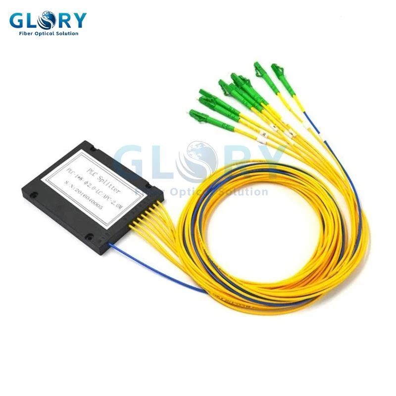
Glory Optical 1×8 ABS box PLC splitter; connectorized and unconnectorized configurations should be specified separately.
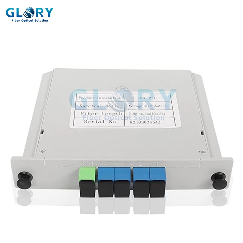
A Glory Optical plug-in cassette is a separate PLC packaging option for modular panel access and replacement.
Key Considerations When Choosing an Optical Splitter
| Buying Factor | What to Check | Why It Matters | Practical Direction |
|---|---|---|---|
| Equal or unequal split | Equal 1×N distribution or a tap such as 10/90 | This is the first technology decision | PLC for common equal PON splits; FBT remains useful for low-count unequal ratios |
| Splitting ratio and link budget | Worst-path fiber, connector, splice, splitter, coexistence element, and repair margin | Higher split counts consume more optical budget | Confirm the ratio against the actual OLT/ONT optical class, not subscriber count alone |
| Wavelength plan | Current GPON/EPON wavelengths and any planned XGS-PON coexistence | IL and WDL must remain acceptable across every required wavelength | Check the product's measured wavelength range and test wavelengths |
| Packaging | Bare fiber, blockless, ABS box, cassette/LGX, or rack mount | Determines footprint, protection, maintenance access, and field labor | Use actual dimensions and enclosure drawings, not package name alone |
| Connector condition | Unconnectorized, one-side connectorized, or both-side connectorized | Each mated pair changes the installed link loss and return-loss behavior | State connector type, polish, quantity, and whether IL includes connectors |
| Optical performance | Worst-port IL, uniformity, PDL, WDL, return loss, and directivity | Average loss can hide a weak output port | Request a batch or per-unit test report using the agreed wavelengths |
| Environmental reliability | Temperature, humidity, vibration, mechanical integrity, and package qualification | Outdoor and long-life PON networks require more than a room-temperature bench result | Define the required Telcordia/IEC qualification and enclosure rating in the RFQ |
Standards and External Technical References
ITU-T G.671: use this as the terminology and transmission-parameter reference for optical components and subsystems, including insertion loss, wavelength dependence, polarization dependence, return loss, and directivity.
ITU-T G.984.2: check the GPON physical-media specifications and optical budget class used by the selected OLT and ONT.
ITU-T G.9807.1: use the XGS-PON physical-layer requirements when the same ODN is expected to support or coexist with 10-Gbit/s symmetric PON service.
Telcordia GR-1209-CORE and GR-1221-CORE: these documents cover generic and reliability-assurance requirements for passive optical components, including operation under adverse environmental conditions.
A standards reference does not prove that a particular unit complies. The supplier should provide the applicable test method, qualification statement, and batch or unit data for the ordered configuration.
Glory 1×N PLC Splitter Insertion-Loss Reference
The values below are taken from Glory Optical's public 1×N PLC splitter product data. The stated conditions are G.657A1/G.657A2 single-mode fiber and a 1260–1650 nm operating range. The page lists an additional 0.3 dB insertion loss per connector. It does not label these values as "standard" or "premium" grade, so the required grade and acceptance limit must be confirmed in the RFQ and factory test report.
| Split Ratio | Listed IL Specification | Wavelength Condition | Connector Condition | Grade / Acceptance Note |
|---|---|---|---|---|
| 1×2 | 3.8 dB | 1260–1650 nm | Base value; add 0.3 dB per connector | Public page does not state grade; confirm report |
| 1×4 | 7.1 dB | 1260–1650 nm | Base value; add 0.3 dB per connector | Public page does not state grade; confirm report |
| 1×8 | 10.2 dB | 1260–1650 nm | Base value; add 0.3 dB per connector | For an ABS product, verify separate typical/max and connector-included values |
| 1×16 | 13.5 dB | 1260–1650 nm | Base value; add 0.3 dB per connector | Confirm worst-port IL and uniformity |
| 1×32 | 16.8 dB | 1260–1650 nm | Base value; add 0.3 dB per connector | Confirm batch/per-unit report before budget approval |
| 1×64 | 20.5 dB | 1260–1650 nm | Base value; add 0.3 dB per connector | Verify optical class and engineering margin |
Theoretical split loss, a bare-device datasheet value, a connectorized module value, and the installed end-to-end loss are different numbers. Use the exact ordered configuration and agreed test reference method.
For the acceptance workflow, see How to Read a Fiber Optic PLC Splitter Test Report Before Bulk Ordering. For ratio-level budget decisions, use the 1×16 vs 1×32 PLC splitter guide.
FAQ About FBT, PLC, and PLC Splitter Packaging
Q: Which splitter technology should I choose for a 1×32 or 1×64 equal PON split?
A: PLC is normally the practical choice for high-count equal splitting. The final ratio must still be verified against the OLT/ONT optical class, worst-path loss, and engineering margin.
Q: Can FBT and PLC splitters be used in the same PON?
A: Yes. There is no blanket technical rule against using both. Model every stage using its measured insertion loss, wavelength behavior, split ratio, connector count, and worst output path. A mixed design is unsuitable only when it fails the budget or complicates operations beyond the project's maintenance requirements.
Q: What is the difference between bare fiber and blockless PLC splitters?
A: A bare-fiber PLC unit uses very small fibers and minimal secondary protection for controlled factory integration. A blockless mini-module places the PLC assembly in a compact protective package and is commonly supplied with buffered pigtails for installation inside an enclosure.
.
Does an ABS box PLC splitter always include connectors?
No. ABS box modules may be unconnectorized, connectorized on one side, or connectorized on both sides. The RFQ and test report must state the connector type, polish, quantity, and whether connector loss is included.
Q: Why would I select an FBT splitter instead of PLC?
A: FBT remains useful for low-count and unequal ratios such as 10/90 or 30/70, especially for monitoring taps, sensors, or a secondary optical branch.
Q: How should insertion loss be verified before deployment?
A: Request the report for the actual ordered configuration. Check worst-port IL, uniformity, PDL, WDL, return loss, test wavelengths, connector inclusion, and the test reference method rather than relying on an unlabeled generic table.
Conclusion
Choose the splitting technology first: FBT for low-count or unequal optical taps, and PLC for common broadband equal-split PON distribution. Then select the PLC package according to enclosure space, handling protection, connector strategy, and maintenance access.
Before release, confirm the exact wavelength range, worst-port insertion loss, uniformity, connector inclusion, environmental qualification, and factory test report for the ordered configuration.
For tailored splitter selection support, contact Glory Optical's technical team to discuss your ODN design requirements.
Request a Quote




