


An aerial fiber route can remain optically healthy while its mechanical margin is disappearing. A cable may still pass traffic after its jacket has been pecked, a clamp has begun to slip, or repeated wind vibration has started to fatigue the attachment zone. The visible outage is often the last event in a much longer failure sequence.
Quick Answer: Match the Cable Structure to the Dominant Route Risk
For an aerial fiber optic cable, "outdoor rated" is only the starting point. Wind and ice determine mechanical loading; lightning changes the consequences of metallic elements; high electric fields can damage an unsuitable ADSS jacket; and biological attack may require a harder or armoured protection layer. These requirements can conflict. For example, metallic tape can improve physical protection, but it also changes bonding, grounding and lightning considerations.
| Route condition | First construction decision | Evidence to request | Common specification mistake |
|---|---|---|---|
| Telecom poles, short FTTH spans | Self-supporting drop, Figure-8 or lashed cable matched to span and hardware | Maximum span table, cable weight, installation tension and clamp compatibility | Using one "maximum span" without wind, ice, temperature or sag conditions |
| Longer self-supporting route | Round ADSS construction with a defined strength-member and jacket system | Rated tensile strength, maximum installation tension, long-term load and vibration evidence | Assuming that all ADSS cables with the same fiber count have the same span capability |
| Power-line corridor | ADSS design qualified for the electrical environment and attachment location | Applicable IEC/IEEE test reports, jacket classification and hardware qualification | Treating "all dielectric" as proof that the jacket cannot track or erode |
| Repeated bird or animal damage | Defined protective layer plus route-specific deterrence or relocation | Construction drawing, material identification and relevant mechanical test results | Ordering "bird-resistant cable" without defining how resistance is achieved |
| Metallic messenger or armour | Figure-8 or armoured structure with a project bonding and grounding plan | Metallic-element continuity, corrosion protection and utility approval | Adding steel protection without reviewing lightning and electrical clearances |
For broader route segmentation before choosing an aerial construction, use Glory Optical's eight-step fiber optic cable selection guide. The present guide starts where that general selection process ends: defining the environmental and mechanical evidence needed for the aerial segment.
1. Which Standards Apply to Aerial Fiber Optic Cable?
The standard must follow the application. A telecom-pole cable that is not installed along a power line does not have the same scope as ADSS installed on utility structures.
The current general reference is ITU-T L.102 (11/2025). It covers aerial single-mode optical cables used in outside-plant telecommunications routes that are not along electrical power lines. It classifies self-supporting and lashed constructions and sets mechanical, environmental and test principles. It also makes an important boundary explicit: power-line applications require other specifications.
For ADSS along electrical power lines, IEC 60794-4-20:2018 covers construction, optical, mechanical and electrical performance, installation guidance, environmental conditions and accessory compatibility. IEEE 1222-2019 with Corrigendum 1-2025 is another relevant reference for ADSS cable on utility facilities. The 2025 corrigendum corrects points in the aeolian-vibration testing provisions, so an RFQ should state the edition and corrigendum rather than writing only "IEEE 1222."
The newly issued IEC 60794-1-119:2025 defines the aeolian-vibration test method for aerial cable families including ADSS, OPGW and OPPC. For ADSS, the procedure uses the maximum installation tension as the cable-load reference and adds controls intended to make the vibration motion and fatigue assessment more consistent.
Compliance note: a standard is not a blanket certificate
"IEC-certified aerial cable" is not a complete procurement statement. Ask for a test report identifying the exact standard edition, laboratory, sample construction, cable diameter, fiber count or product family, test conditions, acceptance criteria and result. Then compare the tested sample with the quoted bill of materials. A report for one sheath, strength-member package or cable diameter should not automatically be applied to every SKU in a catalogue.
Glory Optical can use its OEM/ODM cable review process to align fiber count, jacket, strength members, cable diameter and accessories with the project RFQ. Final standard applicability and route approval remain the responsibility of the project engineer, operator and relevant utility.
2. Wind and Ice: Specify a Load Case, Not a Marketing Span
Maximum span is an output. It is not a stand-alone cable characteristic. It changes with cable weight and diameter, installed sag, temperature, wind pressure, ice thickness, attachment height, terrain exposure and the allowable load of both cable and hardware.
A useful manufacturer reference is Corning's Sag and Tension Applications Engineering Note AEN014. It identifies cable construction, span length, allowable sag, messenger type, temperature, wind and ice as inputs to the calculation. The note also observes that 1% of span is a typical sag starting point, while stressing that the actual condition must come from the route and governing rules.
A ratio that explains many field failures
For the same span and distributed load, the simplified parabolic relationship makes horizontal tension approximately inversely proportional to sag. Reducing sag from 1.0% of span to 0.5% therefore approximately doubles the horizontal tension before other nonlinear and temperature effects are considered. A visually "tight" installation is not automatically a safer installation.
This ratio is a screening insight, not a final design calculation. The final sag-tension study should use the actual cable stress-strain data, creep behavior, temperature cases, wind and ice load, pole geometry and local code.
Use three load cases in the RFQ
| Load case | Purpose | Minimum project inputs |
|---|---|---|
| Installation | Prevents excessive pulling or stringing load during placement | Installation temperature, target sag, maximum installation tension, roller and bend conditions |
| Normal service | Controls long-term fiber strain, clearance and creep | Temperature range, everyday wind, long-term tension and clearance requirements |
| Extreme weather | Checks survival under the governing combined event | Extreme wind, ice thickness and density, concurrent temperature and required safety factors |
The clamps must be evaluated in the same load cases. A suspension clamp supports an intermediate point; a dead-end or tension clamp transfers longitudinal load at a termination or angle point. Glory Optical's guide to aerial cable clamps and suspension hardware explains these roles. Do not approve a cable and choose the fittings later from diameter alone.

Real Glory hardware image: the H3 fiber optic cable dead clamp. Release it only after cable diameter, grip mechanism, installation direction and design load are matched to the span calculation.
3. Lightning and Electric Fields: "All Dielectric" Solves Only Part of the Problem
A metallic messenger, armour tape or strength member can provide useful mechanical protection, but it also creates an electrically continuous element that may require bonding, grounding, separation and lightning coordination. ITU-T K.47 addresses protection of telecommunication lines with metallic conductors against direct lightning flashes. The exact protection arrangement must follow local utility rules and the route design.
ADSS removes metallic conductors from the cable, but that does not make every ADSS jacket suitable for every pole position. In polluted or wet environments near energized conductors, surface leakage can dry in bands and promote arcing, tracking and jacket erosion. The electrical field at the attachment point, contamination level, sheath material and hardware geometry therefore matter alongside the system voltage.
A manufacturer example helps show why "high voltage" is not a complete specification. Prysmian describes track-resistant ADSS jackets for proximity to high-voltage lines and explicitly links them to dry-band arcing and corona exposure. This is evidence that jacket selection is an engineered option, not an automatic property of the word ADSS.
Electrical-environment fields to put in the RFQ
- Telecom-only pole route or shared power-utility structure.
- Nominal and maximum system voltage.
- Proposed attachment coordinates and clearance from energized conductors.
- Pollution severity, coastal salt exposure and industrial contamination.
- Required standard and test-report edition.
- Standard PE or track-resistant sheath requirement.
- Metallic elements, continuity, bonding and grounding requirements.
- Utility-approved fittings and installation method.
For a nonmetallic self-supporting construction, review the Glory Optical ADSS outdoor cable as a configurable starting point. The public product page does not by itself approve a span or power-line position; request the construction drawing, load table, jacket option and applicable test evidence for the quoted configuration.

Glory ADSS construction illustration. The dielectric load path removes a metallic messenger, but jacket grade, attachment position and compatible fittings still require project-specific approval.
4. Bird Damage and Biological Attack: Define the Protection Mechanism
"Bird-resistant fiber optic cable" is not a sufficiently defined standard product class. The RFQ should describe the observed attack, where it occurs and which protective mechanism is expected. The current ITU-T L.161 framework covers biological attacks on telecommunications plant, their damage patterns and protection approaches.
The key design conflict is easy to miss. ITU-T L.102 notes that all-dielectric protective designs can provide different levels of animal resistance, while metallic tapes generally provide the strongest physical barrier against rodent or gopher attack. Adding metallic protection, however, changes weight, flexibility, grounding and lightning considerations. The route risk must therefore decide whether the correct response is a harder all-dielectric layer, metallic armour, local mechanical guards, route relocation or a combination.
Separate jacket damage from load-path damage
| Inspection finding | Immediate optical result | Hidden engineering risk | Decision |
|---|---|---|---|
| Outer sheath marked but not penetrated | Usually no measurable change | Repeated attack or UV/moisture entry may follow | Record location, identify cause and increase inspection frequency |
| Armour or strength layer exposed | Link may remain within budget | Reduced tensile margin, corrosion path or water entry | Engineering review; do not accept on optical continuity alone |
| Tube deformation or local crushing | Intermittent or wavelength-dependent loss | Microbending can worsen under wind, ice or low temperature | Inspect and test at project wavelengths; replace damaged section when integrity is uncertain |
| Strength system partly severed | Fibers may still carry service | Next weather load can convert partial damage into a full break | Treat as a structural failure, not a cosmetic jacket defect |
Glory Optical's squirrel-damage repair and prevention guide provides the companion restoration workflow. It is intentionally separate from this article: the present decision is how to specify the cable before deployment; the repair guide starts after damage is discovered.
5. ADSS, Figure-8 or Lashed Cable: Choose the Load Path First
The structural question is not simply "armoured or unarmoured." It is: which element carries the span load, and how is that load transferred into the pole?
| Construction | How the span is supported | Best-fit route | Critical checks |
|---|---|---|---|
| Round ADSS | Dielectric strength members within the cable body | Self-supporting telecom or approved utility-pole routes | Span/load table, fiber strain margin, jacket class, dead-end and suspension compatibility |
| Figure-8 | Integral messenger joined to the optical cable by a web | Telecom poles and defined short-to-medium spans | Messenger material, corrosion, grounding if metallic, web behavior and matched clamps |
| Lashed cable | Separate messenger carries the load; cable is attached by lashing wire or clips | Existing messenger routes and overlash projects | Messenger residual capacity, bundle diameter, lashing method, clearance and make-ready approval |
| Self-supporting FTTH drop | Small integrated messenger or parallel strength members | Short final spans from pole to premises | Drop length, entry angle, clamp range, wall anchor and bend control |
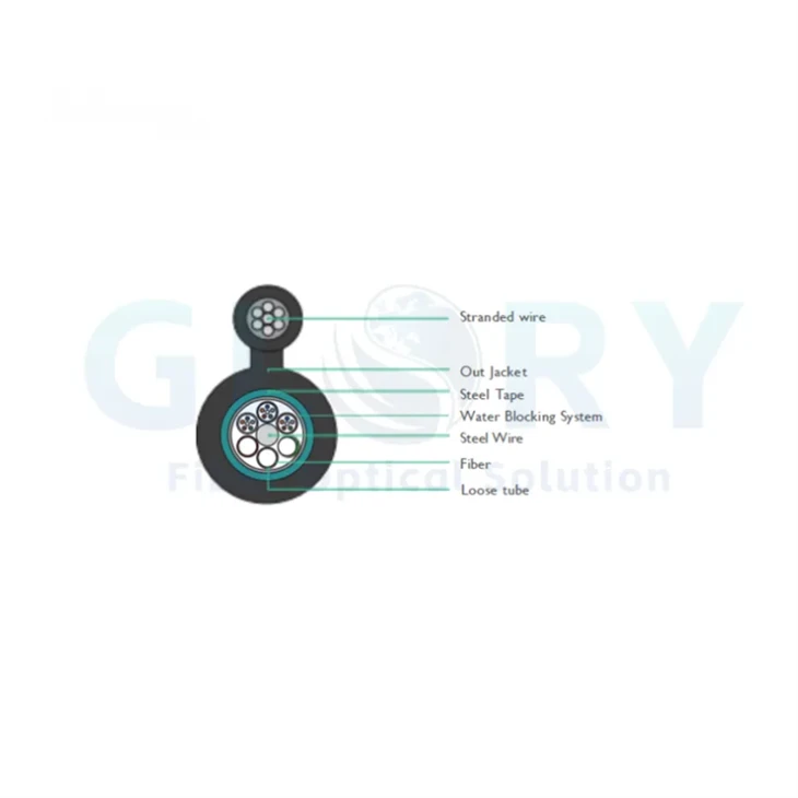
The GYTC8S Figure-8 outdoor cable is relevant when an integral messenger and corrugated steel tape suit the telecom-pole route. Its metallic construction means it should not be substituted for an all-dielectric utility-pole design without reviewing electrical requirements. For purchasing teams checking steel messenger and armour roles, the article on steel wire quality in fiber optic cable explains why armour, tensile members and messengers must be specified separately.

Real GYTC8S structure image from Glory. The integral messenger carries the aerial span while the corrugated steel tape protects the optical core; both must be included in the electrical and mechanical review.
6. The Glory Aerial Route Release Gate: Ten Inputs Before Quotation Approval
The following is a Glory Optical quotation-stage planning framework developed to prevent a catalogue model from being approved before the route is defined. It is not a replacement for a pole-loading study, utility approval or local code.
- Application: feeder, distribution, subscriber drop, FTTA or utility communications.
- Route ownership: telecom-only poles, shared utility poles or dedicated power-line structures.
- Span set: typical span, longest span, angle points, road crossings and elevation changes.
- Weather: installation and service temperatures, governing wind and ice cases.
- Sag and clearance: target installed sag, minimum ground clearance and crossing clearance.
- Electrical environment: system voltage, attachment position, pollution and required sheath class.
- Biological history: birds, squirrels, rodents, insects or vegetation contact observed on the route.
- Cable BOM: fiber type/count, cable OD, weight, strength members, water blocking, armour and sheath.
- Hardware BOM: dead-ends, suspension clamps, armour rods, dampers, downlead clamps and storage brackets.
- Evidence package: drawing, datasheet, load table, test reports, batch checks and installation instructions.
If any of Inputs 2–6 is unknown, the quotation should be marked for engineering review rather than treated as an approved deployment configuration. This gate creates a traceable handoff between route survey, cable manufacturing and installation.
7. Convert the Route Risks into an Acceptance Package
Optical attenuation alone cannot prove that an aerial system retains mechanical or environmental margin. Acceptance should connect the ordered construction, factory evidence and field condition.
| Evidence layer | Required record | What it prevents |
|---|---|---|
| Design | Route load cases, sag-tension output, pole and hardware schedule | Using a valid cable in an invalid span or attachment position |
| Product | Approved construction drawing, material BOM, cable OD/weight and strength data | Substituting a visually similar cable with different mechanical behavior |
| Qualification | Applicable ITU/IEC/IEEE test reports with sample identity and revision | Generic "compliant" claims that cannot be matched to the ordered SKU |
| Production | Drum/batch records, attenuation, dimensional and routine test results | Accepting qualification evidence without batch-level traceability |
| Installation | Installed sag, clamp position, torque where applicable, bend and entry photos | Passing factory evidence while creating damage during installation |
| Optical baseline | Bidirectional OTDR where required, end-to-end loss and event map | Losing the baseline needed to distinguish later cable, splice and connector changes |
Within the scope of ITU-T L.102, the recommendation defines small "no change" thresholds for test evaluation, including 0.05 dB at 1550 nm for attenuation change and 0.05% for fiber-strain change. These values are test criteria within that recommendation, not universal field acceptance limits. The project must state the relevant test method, uncertainty and product scope.
For the wider cable-quality workflow, see how to distinguish fiber optic cable quality. For installation handover and ODN records, use the FTTH installation and testing checklist.

Glory GL-GPJ09 aerial mounting arrangement. Closure capacity is only one acceptance field; also record bracket position, cable-port sealing, strength-member retention and service-loop geometry.
8. Glory Optical Product Starting Points for Aerial Projects
Use these real Glory products to start the cable-and-hardware BOM. They are configuration starting points-not automatic approvals for every span, voltage or biological environment.



The images above are loaded from the linked Glory Optical product pages. Final supply follows the approved drawing, quoted bill of materials and project-specific test package.
Browse by component
Continue route and ODN planning
Turn the route data into a matched cable-and-hardware BOM
Send Glory Optical the span schedule, wind/ice cases, pole arrangement, voltage environment, biological history, fiber count and required standards. A route-defined RFQ is more reliable than selecting the cable, clamp and closure independently.
Submit project requirements Review OEM/ODM options Contact Glory Optical9. Frequently Asked Questions
Q: What is the best cable for an aerial fiber optic route?
A: There is no single best construction. Short FTTH drops may use a self-supporting drop cable; telecom-pole routes may use Figure-8 or lashed cable; and longer or utility-adjacent routes may require ADSS. Select from span, wind, ice, temperature, electrical environment, biological risk and hardware compatibility.
Q: Is ADSS fiber optic cable immune to lightning?
A: ADSS contains no metallic conductor, so it avoids several conduction and grounding issues associated with metallic messengers or armour. It is not automatically immune to every electrical risk. Near energized lines, the attachment position, pollution and jacket resistance to tracking and erosion still require engineering review.
Q: Does a larger cable sag reduce tension?
A: Under a simplified equal-span and equal-load comparison, more sag reduces horizontal tension. Cutting sag from 1.0% to 0.5% of span approximately doubles the horizontal tension. Final values require a product-specific sag-tension calculation.
Q: Can armoured cable prevent bird damage?
A: Armour or another hard protection layer can improve resistance, but 'armoured' must identify the actual material and coverage. Metallic armour also adds weight and changes grounding and lightning requirements. Repeated attack may also require local guards, deterrence or route changes.
Q: Which standard applies to ADSS cable on power lines?
A: IEC 60794-4-20 and IEEE 1222 are relevant references for ADSS used along power lines. The RFQ should name the exact edition; for IEEE 1222-2019, include Corrigendum 1-2025. Utility rules and local codes may impose additional requirements.
Q: Is an IEC-compliance statement enough for cable acceptance?
A: No. Request the specific test report, standard edition, laboratory, tested construction, conditions, criteria and result. Confirm that the report applies to the quoted cable BOM, then retain batch and field acceptance records.
Q: What information should be sent to an aerial cable supplier?
A: Send the route type, typical and maximum spans, temperatures, wind and ice cases, target sag, clearances, pole and voltage environment, biological risks, fiber count, joint locations, hardware requirements and applicable standards.
10. Specify the Aerial System, Not Just the Cable
The most dependable aerial fiber specification begins with the route and ends with an evidence package. Wind and ice define the load; lightning and electric fields constrain metallic elements and sheath selection; biological attack determines whether additional structural protection is justified; and the cable, clamps and closures must transfer loads as one system.
The purchasing rule is simple: never accept fiber count, jacket name and maximum span as a complete aerial-cable specification. Require the load cases, exact construction, compatible hardware and test-report identity that connect the factory BOM to the installed route.
Standards and Engineering References
- ITU-T L.102 (11/2025), Optical fibre cables for aerial application
- ITU-T L.161, Protection of telecommunication cables and plant from biological attack
- ITU-T K.47, Protection of telecommunication lines against direct lightning flashes
- IEC 60794-4-20:2018, Family specification for ADSS optical cables
- IEC 60794-1-119:2025, Aeolian vibration test method
- IEEE 1222-2019/Cor 1-2025, ADSS cable testing and performance
- Corning AEN014, Sag and Tension
Engineering review note: This article supports early planning, RFQ development and procurement review. It does not replace local codes, utility make-ready approval, product-specific installation instructions, pole-loading analysis or a certified project design.





