


What a Fiber Optic Termination Box Does
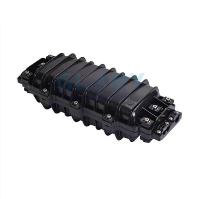
A fiber optic termination box (FTB) is the protected enclosure where an incoming fiber optic cable ends and its individual fibers are spliced, secured, and presented on adapter ports for connection to patch cords or subscriber equipment. It is the last managed passive point in the link before the signal reaches an ONT, switch, or end device - the component that turns a raw, fragile cable into an organized, serviceable interface. In FTTH, FTTB, and equipment-room cabling, it protects splices, controls bend radius, and keeps the network maintainable over the service life of the installation.
Across the industry the same product is sold under several names: fiber termination box, optical terminal box (OTB), fiber optic terminal box, and - in access-network contexts - FTTH termination box. The function is consistent regardless of the label.
A fiber optic termination box (FTB) terminates and protects fiber at the end of a cable run. It performs four core jobs - fixing the incoming cable, splicing fibers to pigtails, terminating them on adapter ports, and storing slack at a controlled bend radius. Common port counts are 2, 4, 8, 12, 24, and 48. It is mounted on a wall, in a rack, or on a pole, with an IP rating chosen to match the environment. In typical field acceptance, a clean, correctly mated connector is usually targeted at ≤0.3 dB insertion loss, subject to the project specification and test method.
The four functions every FTB performs
- Fixing & strain relief: the incoming cable is clamped so mechanical load never reaches the glass.
- Splicing: fibers are fusion-spliced to pre-connectorized pigtails inside a splice tray, with each splice protected by a heat-shrink sleeve. In well-controlled field work, fusion-splice loss is commonly targeted around 0.05 dB; readings consistently above 0.1 dB should be investigated before the box is closed.
- Termination: pigtail connectors plug into an adapter panel, presenting clean, testable ports.
- Storage: excess fiber is coiled in the tray above the minimum bend radius so it can be re-worked later without cutting.
Where the FTB sits in the ODN
In a PON deployment, the Optical Distribution Network (ODN) runs from the OLT (Optical Line Terminal) at the central office, through feeder cable to a splitter cabinet or outdoor fiber distribution box, then as individual drop cables to each subscriber premise. The FTB sits at the far end of the drop: it is the terminal point where the drop cable is anchored and each subscriber fiber is presented as a serviceable adapter port. On the other side of that port, a short patch cord connects to the ONT (Optical Network Terminal), which performs the optical-to-electrical conversion. In both GPON and XGS-PON deployments, APC-polished connectors are typically specified at the FTB to minimize back reflection and support stable network performance.
Many FTTH drop cables use bend-insensitive fiber such as G.657.A2. This makes routing inside compact wall-mount boxes more forgiving than traditional single-mode fiber, but it does not remove the need for controlled slack storage and careful tray routing.

Termination Box vs Distribution Box vs ODF vs Splice Closure
This is one of the biggest sources of confusion in fiber procurement, and the question many buyers actually have when they search for a "termination box." These four devices overlap in components - they can all fix, splice, or store fiber - but they sit at different layers of the ODN and are not interchangeable. Choosing by product name rather than network role is how projects end up re-cabling at the first expansion.
| Device | Network role / ODN layer | Typical ports | Where it lives | Splitter inside? |
|---|---|---|---|---|
| Termination Box (FTB / OTB) | Final termination - subscriber or building end of the drop | 2–48 | Apartment, corridor, building entry, desktop | Optional |
| Distribution Box (FDB / NAP) | Distribution point - splits feeder to multiple drop cables | 8–48 | Outdoor wall, pole, pedestal, street cabinet | Usually yes (PLC splitter) |
| ODF (Optical Distribution Frame) | Central office / data-center backbone management | 12–576+ | CO equipment room, data-center cable tray | Rarely |
| Splice Closure | Mid-span cable joint - no subscriber access | 12–576 splices | Buried, aerial, manhole, mid-route | Optional |
The clean mental model: a splice closure joins fiber and leaves it joined - there are no plug-in ports, it is sealed and forgotten mid-route. A termination box ends the fiber and presents ports you can plug into and unplug. A distribution box is a termination box that also splits one feeder into many drops, usually with a 1:8 or 1:16 PLC splitter inside; in FTTH practice this is often called a NAP box (Network Access Point) or splitter cabinet. An ODF is a termination box scaled up for the central office, where density and standardized management matter more than proximity to the subscriber. If you can unplug a connector, it is not a closure. If it sits between an OLT port and a group of drop cables with a splitter inside, it is a distribution box, not a termination box.
Box Types by Mounting and Environment
FTBs are categorized first by how they mount, which in turn drives material, sealing, and capacity. The three dominant form factors:
Wall-mount termination box
The default for FTTH single-dwelling and MDU work. Compact, lightweight PC+ABS or ABS enclosures mounted at building entries, in MDU corridor risers, or inside individual apartments. Capacities run 2 to 24 ports. Indoor units prioritize footprint and ease of access; outdoor wall-mount units add UV-resistant material and IP sealing. In MDU riser deployments, a 12- or 24-port wall-mount box at each floor serves as the handover point between the vertical distribution cable and individual apartment drops - a common ODN topology in apartment buildings where running individual drop cables directly to a street-level distribution point is impractical.
Rack-mount termination box (fiber patch panel)
A 1U or 2U metal unit for the data center and equipment room, frequently called a fiber patch panel. Sliding-drawer designs let a technician pull the tray forward to access splices without de-racking the unit. Conventional densities are 12, 24, and 48 ports per RU; high-density MPO/MTP variants reach 96 to 144 fibers per 1U, making them the practical choice for 40G/100G parallel-fiber backbone applications where individual SC or LC ports would require unmanageable cable volumes. This is where the FTB merges into ODF territory - the distinction becomes one of scale rather than function.
Outdoor fiber termination box and pole-mount termination box
Engineered for harsh environments: UV-stable PC+ABS or PP+GF composite, gasket sealing, anti-theft locking, and a tensile-tested cable entry. These reach IP65 to IP68 and mount on exterior walls or utility poles. Small outdoor scenarios (homes, surveillance drops) use 4–12 core plastic boxes; campus and aggregation points use 24-core-plus metal boxes with redundant ports reserved. In sites where vandalism or accidental mechanical impact is a realistic concern - streetside poles, ground-level pedestals - look for an IK rating in addition to the IP designation. IK10 (per IEC 62262) specifies resistance to 20 joules of impact energy and is the practical standard for pole-mount and pedestal-mount distribution points. IP covers ingress; IK covers impact; a box in a high-traffic area needs both.
A fourth form factor worth noting: pedestal and dome enclosures for buried or underground distribution points, typically IP68-rated and designed for flood resistance rather than wall attachment. These are used in buried-infrastructure FTTH builds where the distribution point is set in a below-grade vault rather than on a pole.

Two secondary structural styles cut across all three: straight-through (butt-joint) boxes route cable linearly and support branching, while splitter-ready boxes reserve space to mount a PLC splitter internally, turning the FTB into a compact distribution point for GPON/XGS-PON access networks.
Port Capacity: How to Actually Size It
Most selection guides list port counts and stop. The harder question - the one that determines whether you return to re-cable in two years - is how to size capacity correctly. The field rule that consistently avoids under-sizing: plan to populate no more than 80% of ports at commissioning, reserving 20% for growth and re-work.
| Site condition | First-choice box | Check before ordering |
|---|---|---|
| Single FTTH subscriber endpoint | 2- or 4-port wall-mount FTB | SC/APC adapter, drop-cable entry, indoor/outdoor rating |
| MDU floor or small office handover | 8- to 24-port wall-mount FTB | Splice tray capacity, labeling space, 20% spare ports |
| Outdoor wall or pole access point | IP65+ outdoor FTB or splitter-ready box | UV-stable material, gland sealing, IK rating if exposed |
| Data center or equipment room | 1U/2U rack-mount patch panel | LC density, cable management, sliding tray access |
| Ports | Typical application | Populate at commissioning |
|---|---|---|
| 2 port | Single dwelling (FTTH residential), surveillance drop, single-tenant entry | 1 fiber + 1 spare |
| 4 port | Small home with dual service, villa with future expansion | 2–3 fibers |
| 8 port | Small MDU floor, small office branch | 6 fibers |
| 12 port | MDU riser, mid-size office, building entry point | 9–10 fibers |
| 24 port | MDU aggregation, campus distribution, data-center row | ~19 fibers |
| 48 port | Rack-mount data center, central-office edge, high-density campus | ~38 fibers |
In a GPON or XGS-PON residential deployment, the ODN carries one distribution fiber per OLT port from the CO to the splitter point, where a 1:32 or 1:64 PLC splitter fans out to individual subscriber drop cables. Each drop cable terminates at one subscriber's FTB - typically a 2- or 4-port box. The sizing question at the distribution box is different: a 1:32 splitter serving 32 subscribers requires a distribution box with at least 32 drop ports plus spare capacity. Under-sizing the distribution box at the splitter point forces a costly ODN re-work as subscriber take-up grows; over-sizing the subscriber FTB wastes money at every home-pass. Specify these two differently.
A subtle field trap: an 8-core box only delivers 8 working ports if tray routing and slack storage are done correctly. If your design thinks in raw fiber count rather than usable adapter ports, you can specify a box that physically holds the fibers but can't be terminated cleanly. Design around usable ports, and confirm the splice tray's stated splice capacity separately - they are not always the same number.
SC vs LC Adapter Selection
The adapter panel is the user-facing interface of the box, and the connector format you specify here propagates to every patch cord and pigtail in the deployment. Two formats dominate FTB work:
| Factor | SC | LC | MPO/MTP |
|---|---|---|---|
| Footprint | Larger (square latch) | Half the size (small form factor) | Multi-fiber ribbon connector |
| Fibers per connection | 1 | 1 | 8, 12, or 24 |
| Density | Lower | ~2× per panel vs SC | Highest - 144 fibers/1U typical |
| Dominant use | FTTH access, GPON/XGS-PON, general field termination | Data center, high-density panels, enterprise | 40G/100G backbone, structured cabling backbone |
| Field handling | Easy push-pull, glove-friendly | Compact; tighter to access when dense | Requires keyed alignment; less common in FTTH |
| Typical polish | SC/APC for PON (green boot, 8° angle) | LC/UPC or LC/APC depending on application | APC variant available; UPC more common |
For any PON / FTTH access deployment, specify SC/APC (angled physical contact, 8°, green boot), not UPC. SC/APC connectors are generally preferred in GPON and XGS-PON networks because their angled endface reduces back reflection compared with UPC connectors. Mixing APC and UPC components on the same connection can increase insertion loss and degrade optical performance. The boot color is your safeguard: green meets green. Blue (UPC) meets blue. Never cross them on the same connection.
IP Rating and Matching the Box to the Environment
The most expensive FTB mistake is not buying the wrong port count - it's deploying an indoor-rated box where moisture, dust, or sun will reach it. Once water enters an enclosure, splice loss climbs and the box fails on a timeline measured in months, not years. Match the Ingress Protection rating to the real environment, and if the location sees rain, condensation, dust, or direct sun, treat it as outdoor regardless of whether it is technically "inside."
| Rating | Protection | Use for |
|---|---|---|
| Indoor (no IP / IP30) | Basic dust only | Conditioned indoor space, equipment rooms |
| IP65 | Dust-tight; resists water jets from any direction | Outdoor wall/pole where rain & dust occur, no submersion risk |
| IP67 | Dust-tight; temporary immersion to 1 m for 30 min | Exposed outdoor, occasional flooding risk, ground-level installs |
| IP68 | Dust-tight; continuous submersion at manufacturer-specified depth | Buried, pedestal, flood-prone locations, harsh-climate aggregation |
| NEMA 4X | Weather + corrosion resistance (North American equivalent) | US/Canada outdoor specs, coastal or high-humidity environments |
| IK08 / IK10 | Impact resistance - 5 J (IK08) or 20 J (IK10) per IEC 62262 | Pole-mount, streetside, pedestal, any site with vandalism or strike risk |
IP ratings are validated under controlled laboratory test conditions and at time of manufacture. Real-world performance depends on gasket material quality, UV stability of the enclosure body, and installation quality. High-quality gasket materials maintain sealing performance better over long-term outdoor exposure and temperature changes. For outdoor units specify UV-stabilized PC+ABS or PP+GF composite; unstabilized material becomes brittle within 2–3 years of sun exposure in high-UV climates. A correctly installed outdoor FTB with quality materials lasts 10–20 years; a correctly rated but poorly installed box can fail within two rainy seasons.
For outdoor units, also confirm the cable-entry strain-relief specification against the cable type and project requirement. Some outdoor cable assemblies are specified with high tensile-load requirements under IEC 60794-related mechanical tests, but the correct value depends on the cable structure, gland design, and installation method. For accessible outdoor installations, add an anti-theft lock or tamper-resistant closure.
Step-by-Step Installation
A box can be mounted correctly and still fail later because fibers were routed too tightly, splices were stacked wrong, or the cable entry was never properly secured. The sequence below reflects field-proven practice for FTTH termination work. Safety first: wear laser-safety glasses, never look into a live fiber, and take care with glass shards from the strip-and-cleave process.
- Confirm box type and environment.Before drilling, verify the box IP rating matches the location's actual conditions (not just its nominal classification), and that the port count fits your design plus the 20% reserve. Confirm you have the correct adapter polish - SC/APC for PON.
- Mount in a stable, accessible location.Indoors, ensure wall or rack space and adequate clearance for cable management. Outdoors, confirm the mount surface can support the loaded box weight under wind load, avoid south-facing direct sun exposure on plastic enclosures without UV shading, and leave working room for future access. Ground metal enclosures per local electrical codes.
- Secure cable entry and strain relief.Route the incoming cable through the gland and clamp it so all mechanical load is taken by the strain-relief clamp, never the fiber. Tighten the gland to the manufacturer's torque spec. Check that the gland compression ring creates a water-tight seal on the cable jacket - a common omission on outdoor installs.
- Strip, clean, and prepare the fiber.Remove jacket and buffer to the lengths the splice tray requires; clean each fiber with lint-free wipes and isopropyl alcohol. Contamination at this stage becomes splice loss. Maintain a minimum of 0.5–1.0 m of cable slack inside the box to absorb future thermal contraction without transmitting tension into the tray.
- Fusion-splice fibers to pigtails.Cleave, align, and fuse each fiber to a pigtail. A good fusion splice contributes roughly 0.05 dB; anything consistently above 0.1 dB should be re-done before proceeding. Protect each splice with a heat-shrink sleeve and seat it correctly in the splice tray's designated holder - do not stack or stack-lean sleeves.
- Store slack at controlled bend radius.Coil excess fiber in the tray, keeping every bend above the minimum long-term bend radius specified for the cable. Standard G.652.D fiber is commonly designed with a larger bend-radius allowance, while G.657.A2 bend-insensitive drop cable supports much tighter routing. Even with G.657.A2, avoid forced tight-radius coils that stress the coating. Tight loops that look acceptable on the day of install can cause macrobend loss as the enclosure flexes through seasonal temperature cycles.
- Terminate on the adapter panel.Plug each pigtail connector into its adapter port, matching polish (APC green to APC green). Keep dust caps on all unused ports throughout installation - the endface contamination from a single finger contact can require re-cleaning and re-testing.
- Label every port.Mark each port and fiber per your labeling scheme before closing. Unlabeled boxes are the single most common cause of repeat truck-rolls; the cost of a label printer and 5 minutes per box recovers in the first fault call.
- Test, verify link budget, and document.Measure insertion loss and return loss per port with a light source/power meter. A common field target is ≤0.3 dB per clean mated connection, but the project acceptance limit should follow the specified test standard and equipment class. If an end-to-end measurement is possible, verify the accumulated ODN loss from OLT to ONT stays within the applicable power-class budget. Trace with an OTDR if practical, and store the trace file as part of the project handover documentation. A link that passes on day one with no margin can fail after component substitution, connector contamination, or a weather event.
- Seal and close.Confirm gaskets are fully seated and undamaged, close the cover, lock outdoor units, and re-inspect the cable entry seal. For outdoor boxes, a final tug test on the cable confirms the gland is properly holding mechanical load.

Maintenance & Cleaning Essentials
FTBs are passive devices and largely maintenance-free when correctly installed. The faults that do occur are almost always connector contamination, gasket degradation on outdoor units, and bend-radius violations that develop slowly under thermal cycling. A simple maintenance schedule prevents all three:
On initial commissioning: clean and inspect all endfaces, test every active port, confirm all unused ports are capped. Annual (outdoor units): inspect all cable-entry glands and gaskets; re-torque glands that show movement; look for UV-related surface cracking on the enclosure body. Replace foam-type gaskets that show permanent compression. On any fault notification: inspect and clean all connectors at the affected box before replacing any hardware - the majority of insertion-loss faults are contamination, not component failure. After any access event: re-inspect all open ports for dust before re-closing.
- Keep endfaces clean. Connector contamination is the primary cause of intermittent links. Inspect with a fiber microscope per the IEC 61300-3-35 endface cleanliness standard (Zone B criteria allow contamination in the outer zones but not in the core contact zone) before mating. Use a dedicated fiber cleaner; avoid random wipes that leave lint or residue.
- Cap unused ports. Dust caps stay on until a port is activated. An open adapter accumulates the exact contamination that fails the next connection, often immediately.
- Do not touch endfaces. Skin oils are a contaminant. Connectors should not contact surfaces, tools, or fingers - handle by the body only.
- Inspect outdoor gaskets and glands on a maintenance cycle. A degraded gasket or loose gland is a slow-motion failure: the box remains functional as moisture levels rise until a single temperature event drives condensation onto the splice tray.
- Ground before servicing energized adjacent equipment, and inspect connectors before cleaning if they appear damaged.
The Field Failures We Actually See
These are the recurring faults from FTTH and FTTB deployments - none of them are exotic, and every one is preventable at install time:
- Bend-radius violations in slack storage. Over-coiled or pinched fiber in the tray produces macrobend loss that doesn't always show until the link is loaded or the box undergoes its first winter thermal cycle. This is the most common avoidable fault, and it is invisible to a quick visual inspection.
- Wrong enclosure for the environment. An indoor box on a damp exterior wall, a transit-zone box exposed to condensation, a plastic box in a high-UV outdoor environment without UV stabilization. It works on day one and fails by the next wet season or after the first summer of direct sun exposure.
- APC/UPC polish mismatch. Green-to-blue connections drive insertion loss up and return loss down - often enough to fail a PON link. The damage is not always obvious on a quick power-meter reading but shows up clearly on an OTDR trace or when the OLT reports upstream BER faults.
- Unmanaged strain relief. Mechanical load reaching the glass instead of the cable clamp. The initial measurement may be acceptable; slow degradation from cable movement causes the splice to develop micro-cracks at the heat-shrink boundary, eventually producing an intermittent fault that is hard to localize.
- No labeling. The cheapest step to skip and the most expensive to recover. Every truck-roll after an unlabeled install involves a technician tracing unknown fiber before they can begin the actual repair.
- Stacked or crushed splice protectors. Sleeves not seated in their designated holders, stressing the splice mechanically. Common when a technician is working in a cramped outdoor box and does not take the time to seat each sleeve before routing the pigtail.
- Thermal cycling degradation on outdoor units. An incorrectly specified gasket material or an under-torqued cable gland may appear sealed at installation but develops creeping moisture ingress over winter-spring freeze-thaw cycles. The first symptom is elevated insertion loss on specific ports - typically the ports closest to the cable entry - not a complete failure. This failure mode is often misdiagnosed as a connector issue and requires opening the box to diagnose correctly.
Selection Decision Tree
A compact way to converge on the right box for a given site:

Glory Product Matrix: Termination Boxes and Related ODN Boxes
Glory manufactures fiber termination boxes and related ODN enclosure products from a 20,000 m² ISO 9001:2015 facility, shipping to 50+ countries. The table below separates strict termination use from related distribution and splitter-ready roles so buyers do not confuse a subscriber-end FTB with a NAP or distribution box. Connectors and pigtails can be pre-installed at the factory to reduce field labor; specify at order time.
| Model | Role | Capacity | Rating / Material | Best for |
|---|---|---|---|---|
| GL-FTB-4F | Wall-mount, indoor/outdoor | 2 port | Configurable, pre-term option | Single dwelling FTTH, surveillance drop |
| GL-P2-8R | Outdoor terminal box | 8 port | IP65/66, PC+ABS, −40 to +85 °C | FTTH drop termination, small MDU |
| GL-P1-12S | Related distribution box | 12 port | 4-entry feeder + drop | Building entry, MDU riser |
| GL-P1-16R2 | Outdoor termination / distribution box | 16 port | IP65, PC+ABS | Outdoor wall/pole aggregation |
| GL-ODB-16R | Related outdoor ODN box | 16 port | IP68, IK10 impact, PC+ABS | Harsh outdoor, high-impact sites, streetside pole |
| GL-FDB-24D | Related NAP / splitter-ready box | 24 core | IP65, splitter-ready | FTTH outdoor wall, GPON/XGS-PON splitting point |
| GL-A9-48R | High-density distribution enclosure | 48 port | IP65/66, −40 to +85 °C | Campus aggregation, high-density outdoor |
For splitter-based PON designs, pair a splitter-ready box such as the GL-FDB-24D with a Glory PLC splitter (1:8 / 1:16 / 1:32), and terminate drops with factory SC/APC pigtails to keep field splice counts and labor down.
People Also Ask - Straight Answers
-
Q: What is a fiber optic termination box?
A: The protected enclosure where an incoming fiber cable ends and its fibers are spliced, secured on adapter ports, and stored at a controlled bend radius. It is the final passive point before the signal reaches an ONT, switch, or end device, and performs four jobs: fixing the cable, splicing fibers to pigtails, terminating on adapter ports, and storing slack.
Q: What is the difference between a termination box and a splice closure?
A: A splice closure joins two cables mid-route and is sealed shut with no plug-in ports - it lives buried, aerial, or in a manhole and is not accessed in normal operation. A termination box ends the fiber and presents adapter ports you can connect and disconnect, at the building or subscriber end. If you can unplug a connector, it is a termination box, not a closure.
Q: What is the difference between a termination box and a distribution box (NAP box)?
A: A termination box ends fiber at one subscriber or building endpoint. A distribution box (also called a NAP box or fiber distribution box) does the same but also splits one feeder fiber into multiple drop cables - usually with a 1:8, 1:16, or 1:32 PLC splitter inside - and serves as the outdoor distribution point for a group of subscribers in a GPON or XGS-PON ODN. Many outdoor boxes are sold as splitter-ready, meaning they can serve either role depending on configuration.
Q: How many ports does a fiber termination box have?
A: Common counts are 2, 4, 8, 12, 24, and 48. Single-dwelling FTTH uses 2–4 port boxes; MDU floors and offices use 8–24; rack-mount data-center panels run 24–48, with MPO/MTP variants reaching 96–144 fibers. Size for your planned fibers plus roughly 20% reserve, then round up to the next standard count. Do not size exactly to current demand.
Q: What IP rating do I need for an outdoor fiber termination box?
A: IP65 is the practical minimum for outdoor wall or pole mounting where rain and dust occur but submersion is not expected. Choose IP67 for occasional immersion risk (ground-level or flood-prone locations) and IP68 for buried, pedestal, or continuously submerged installations. For streetside or pole-mount boxes where vandalism or accidental impact is realistic, add an IK08 or IK10 impact rating - IP only covers ingress, not mechanical strikes. In North America, NEMA 4X is the equivalent specification for weather and corrosion resistance.
Q: Should I use SC or LC adapters in my termination box?
A: SC dominates FTTH and PON access work - it handles well in the field, particularly with gloves, and is the common format for GPON and XGS-PON drops. LC is the choice for high-density data-center panels where roughly doubling ports per panel matters more than field handleability. For PON deployment, the polish (APC vs UPC) often matters more than the form factor: SC/APC (green boot, 8° angle) is the preferred default because it reduces back reflection and supports better return-loss performance. Avoid mixing APC and UPC in the same optical path unless the network design explicitly allows it.
Q: How does a fiber termination box affect the link budget?
A: Every termination box introduces a small amount of insertion loss through its adapter connections and internal splices. While the loss from a single box is usually modest, it should still be included in the overall network loss calculation and verified during commissioning with appropriate test equipment.
Q: Can the same termination box support both GPON and XGS-PON?
A: Yes, with conditions. The FTB enclosure, splice tray, and strain relief are wavelength-agnostic. What must be checked is the connector polish, loss budget, splitter plan, and end-to-end optical performance. If an existing FTTH deployment was correctly specified with SC/APC throughout and has enough link-budget margin, the physical termination infrastructure is usually compatible with an XGS-PON OLT and ONT upgrade. This is one reason specifying SC/APC at deployment time, even in GPON systems, helps protect future upgrade paths.
Q: What is the maximum insertion loss for a termination box connection?
A: Target no more than 0.3 dB per mated connection in the field, and verify with a power meter or OTDR after termination. A good fusion splice itself adds roughly 0.05 dB; higher readings usually mean connector contamination, a polish mismatch (APC into UPC), or a bend-radius violation in the slack storage. If a single connection reads above 0.5 dB, clean the endface first before replacing any hardware.
Q: Can I install a fiber optic termination box myself?
A: Pre-connectorized (plug-and-play) boxes can be installed without a fusion splicer, and with basic care produce good results. Boxes requiring fusion splicing need a splicer, a fiber cleaver, and trained technique - the skill requirement is real, not a liability disclaimer. The most common self-installation faults are over-coiled slack (bend-radius violation), contaminated connectors (touching endfaces or leaving caps off during work), and using an indoor-rated box in an outdoor or wet location. Wear laser-safety glasses, test before closing, and always label.
Standards and References
- IEC 61300-3-35 - Fibre optic connectors: endface geometry and visual inspection criteria (contamination standard for endface cleaning): iec.ch
- IEC 61300-3-34 - Fibre optic interconnecting devices: attenuation measurement by insertion loss method using OTDR: iec.ch
- IEC 62262 - Degrees of protection provided by enclosures for electrical equipment against external mechanical impacts (IK code): iec.ch
- IEC 60529 - Degrees of protection provided by enclosures (IP rating standard): iec.ch
- ANSI/TIA-598-C - Optical Fiber Cable Color Coding (jacket and connector boot colors, including green = APC): tiaonline.org
- ITU-T Recommendation G.652.D - single-mode optical fibre and cable characteristics (standard SMF): itu.int
- ITU-T Recommendation G.657.A2 - bend-loss insensitive single-mode fibre (7.5 mm long-term bend radius; the standard for FTTH drop cable): itu.int
- ITU-T Recommendation G.984 - Gigabit-capable Passive Optical Networks (GPON): itu.int
- ITU-T Recommendation G.9807.1 - 10-Gigabit-capable symmetric Passive Optical Networks (XGS-PON): itu.int
- The Fiber Optic Association - connector cleaning and inspection reference: thefoa.org





