

The short answer
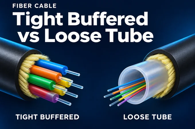
Tight-buffered cable adds an individual protective buffer around each coated fiber, commonly bringing its outside diameter to 900 µm. Loose-tube cable places coated fibers inside a larger tube with room for controlled movement. The first arrangement is convenient to handle at a termination; the second is widely used where environmental isolation and fiber density matter.
Choose between actual cable designs after checking the route and deciding how the ends will be finished. A qualified indoor/outdoor tight-buffered cable can be a sensible choice for a small campus link. A flame-rated loose-tube cable can serve a building backbone. This guide explains where those choices make sense, where they add work, and what to put in the RFQ before comparing prices.
What the buffer actually changes
Start with the fiber rather than the jacket. In common telecom fiber, the glass cladding is nominally 125 µm in diameter. Protective polymer coatings make the coated fiber larger, often described as nominally 250 µm. Reduced-coating designs can retain the same nominal 125 µm glass cladding even when the coated diameter is 200 µm. These dimensions describe different layers.

In a tight-buffered design, an additional buffer closely surrounds each coated fiber. The resulting element is easier to identify, separate and prepare than an unsupported coated fiber. Buffer stripability still matters: two products both described as 900 µm can behave differently with the same stripping tool.
A loose tube contains one or more coated fibers. Tube dimensions, fiber length within the tube, materials and the rest of the cable construction work together to manage movement. The fibers remain coated; calling them bare fibers during normal tube preparation confuses a protected fiber with glass whose coating has been stripped for splicing.
Keep the optical specification separate. Single-mode or multimode, attenuation, operating wavelengths and bend performance belong in their own RFQ fields. A buffer arrangement cannot establish the link speed or transmission distance. Specifying G.652 or G.657 addresses fiber characteristics; it does not describe the whole cable or its installation limits.
A comparison that leaves room for real products
A comparison is useful when it identifies what deserves attention. It becomes misleading when typical features are presented as guarantees. Use the table to shortlist designs, then compare matching part numbers, fiber counts and jacket options.
| Selection point | Tight buffered | Loose tube |
|---|---|---|
| Fiber protection | Individual buffer around each coated fiber | Coated fibers housed inside a larger tube |
| Common strength | Handling and preparation at individual fibers | Environmental isolation and efficient fiber grouping |
| Termination planning | Can simplify compatible direct connectorization | Often spliced to pigtails; protected fan-out is another route |
| Water protection | Available in specifically qualified waterblocked designs | Common in OSP designs; confirm where and how water is blocked |
| Indoor use | Common, subject to the required fire classification | Possible with an appropriate indoor or indoor/outdoor classification |
| Density and size | Distribution and breakout designs differ considerably | Often attractive at higher counts; compare actual outside diameters |
| Bending and pulling | Use the exact cable limits | Use the exact cable limits |
| Optical capability | Set by the specified fibers and completed link | Set by the specified fibers and completed link |
Breakout cable adds another distinction. A typical breakout construction places individually jacketed, reinforced subunits within an outer jacket. Distribution cable usually groups buffered fibers under a shared jacket and strength system. They can both use tight-buffered fibers, yet occupy very different amounts of tray space and require different treatment at the equipment end.
Ask for the cross-section and termination drawing together. A low price for distribution cable is not directly comparable with a breakout assembly if the latter already includes protection that the former still needs at its ends.
There is also no useful universal fiber-count ceiling for the phrase tight buffered. Subunits, central members, armor and jacket arrangements change the finished product. For an expansion plan, record usable spare fibers and available pathway space rather than assuming one construction will always be smaller.
Qualify the route before choosing the construction
Walk the route on paper before requesting cable prices. Mark the wet sections, exposed sections, building entrances, vertical runs and termination spaces. For each section, record the condition the cable will actually face. The most demanding section may be only a few meters long, but a continuous cable must be suitable for it.
Outdoor capability comes from the complete design
Corning provides a useful counterexample to the indoor-only shorthand: its FREEDM One tight-buffered riser family is described as indoor/outdoor, UV-resistant and waterblocked. Its published range includes separate installation and operating temperature limits. That is evidence that an outdoor-capable tight-buffered design exists, rather than evidence that every tight-buffered cable has those properties.
The reverse exception matters too. Corning publishes a gel-free loose-tube riser family for interbuilding and intrabuilding applications. It combines loose tubes with a flame-retardant jacket and waterblocking materials. The construction name alone therefore cannot tell a buyer whether a cable belongs inside a building.
Use these examples to check a quotation. Ask which construction, jacket and qualification the supplier is offering. Do not transfer a manufacturer's family-level description to an unverified substitute. The same caution applies to black jackets: color is easy to photograph, while UV performance depends on materials and qualification.
A wet duct and a building riser ask different questions
For a duct exposed to water, request the cable's water-penetration requirement and supporting evidence. Confirm whether the design blocks longitudinal migration in the tubes, the cable core or both. Also ask what happens at opened cable ends and intermediate access points. Cable waterblocking does not remove the need to design those interfaces.
For the indoor section, identify the required fire classification and verify the offered product's marking or certification. LSZH describes smoke and halogen properties; the label alone does not establish suitability for every riser or plenum application. UL treats application classifications and low-smoke halogen-free evaluations separately. Applicable building-entry and firestopping details must follow the project's local requirements.
If no offered product meets the complete route, split the route at a planned transition. Make that decision early enough to allocate an enclosure, termination space and testing scope. Adding a transition after cable delivery can mean revising the hardware order, work schedule and acceptance plan.
Temperature and water need separate evidence
Loose-tube construction has a sound engineering reason behind its widespread outdoor use. Glass and cable polymers expand and contract differently. A controlled relationship between fiber length and tube length can accommodate some movement without immediately transferring it to the fiber. Corning's application note discusses this thermal behavior and the importance of waterblocking where water and freezing temperatures coexist.
The available accommodation is finite. A damaged tube, poor anchoring or installation outside the qualified limits can still create stress. For selection purposes, a temperature-cycling result for the offered cable is more useful than the unqualified claim that its fibers float freely or remain strain-free.
Operating temperature does not authorize installation
A reel can arrive on a cold morning within the cable's storage range while remaining outside its installation range. That difference changes the work plan. Ask whether the reel needs conditioning, how its temperature will be checked and whether the approved procedure permits work to start. An operating limit describes the installed cable's service conditions; it does not automatically describe the conditions under which the jacket can be bent or pulled.
This is particularly relevant when crews work in unheated buildings, winter compounds or exposed roadside cabinets. Record storage, installation and operation as separate values on the comparison sheet. If a quotation provides one temperature range without naming its purpose, return it for clarification before treating it as compliant.
Waterblocking and enclosure sealing protect different paths
Water may enter around a cable at an enclosure port, or it may travel longitudinally inside a cable. The first problem concerns the port and its seal; the second concerns the cable construction and how opened ends are managed. A successful seal around the outer jacket does not establish that water cannot migrate inside the cable.
Gel-filled and dry waterblocked loose-tube products can both be appropriate. Their preparation steps differ. Ask the installer to open the actual sample and show the cleaning process, tube routing and finished tray. A dry design may simplify one task, but the relevant purchasing question is whether the complete preparation method works reliably with the selected cable and hardware.
Avoid awarding a whole cable family a temperature or water advantage without conditions. State the exposure, request the applicable test method and acceptance result, and keep the manufacturer's limits attached to the approved part number. This gives the site team evidence it can use when weather or access conditions change.
Let the installation limits decide the route details
A cable that fits through a duct may still be unsuitable for the pull. Installation drawings should name the maximum permitted pulling load, the minimum bend radius under installation load and the minimum installed bend radius. Corning's installation guidance explicitly directs installers to the cable-specific specification. Generic diameter multipliers are planning aids, not a replacement for that sheet.
Keep the units visible. Radius is half the bend diameter, so confusing them can leave a guide or storage loop much too small. Also check whether a pulling head, furcation assembly or preterminated end has a larger clearance requirement than the cable itself.
A worked example with assumed cable limits
Suppose two qualified candidates have the following manufacturer-specified limits. These values are hypothetical and are not specifications for either cable family.
| Property | Candidate A | Candidate B |
|---|---|---|
| Outside diameter | 6 mm | 9 mm |
| Minimum radius during installation | 90 mm | 135 mm |
| Minimum installed radius | 60 mm | 90 mm |
| Minimum guide bend diameter during installation | 180 mm | 270 mm |
A route with a 220 mm bend diameter at one entry can satisfy A's assumed installation radius, but not B's. B's final installed bend limit is less demanding than its installation limit; using that smaller value to approve the pull would be a mistake. The solution may be a different entry arrangement or another cable, rather than a different buffer category.
The pulling arrangement also needs a defined load path. Use the manufacturer's attachment method for the cable strength system. Once the cable is in an enclosure, secure the jacket and specified strength members so that handling forces do not reach the opened tubes, exposed fibers or connectors.
For an aerial route, the word loose tube is incomplete. Confirm whether the offered cable is intended for lashing, a messenger-supported arrangement or self-supporting service, and obtain the corresponding hardware and span design. For direct burial, require an explicit suitability statement for that use. Armor, dielectric construction and buffer arrangement answer different parts of the selection problem.
Resolve these questions before the reel reaches site. A short route with several awkward bends can demand more installation planning than a long, straight section of duct.
Choose the termination method before ordering cable
Loose-tube fiber is often fusion-spliced to factory-terminated pigtails in a managed tray. A fan-out kit is a different option: it sleeves individual coated fibers so they can be routed and connectorized using a compatible system. AFL describes kits that take 250 µm fibers into color-coded 900 µm tubes. Such tubing provides handling protection; it is not a universal prerequisite for fusion splicing.

Tight-buffered fibers can simplify compatible direct connectorization, and they can also be fusion-spliced. Check the connector or splice-on connector instructions for accepted buffer diameters, strip lengths, tools and strain relief. The convenient buffer does not remove the need for cleaning, inspection or optical acceptance measurements.
Distribution cable deserves particular care at the end. Its individual 900 µm buffered fibers are not equivalent to separately reinforced patch cords. FOA guidance calls for protection in closed termination hardware, whereas individually jacketed simplex or duplex cables can be handled differently.
Request one finished sample termination using the proposed cable, tray, pigtail or connector. Check whether the lid closes without pressing on fibers, whether adapters remain accessible and whether moving one lead disturbs another. This trial is especially useful when substituting a cable with a different tube count or outside diameter.
For preterminated assemblies, add pulling-head size, connector protection and spare-length storage to the review. Factory termination changes where the work happens; the route and enclosure still have to accommodate the completed assembly.
Design the building entry as part of the link
A campus route can use an outdoor cable that transitions to an indoor cable, or a qualified indoor/outdoor cable that continues through the approved entry arrangement. The better option depends on the product's suitability across the route, available working space and the maintenance plan. Treat the transition as an explicit design choice.

For a transition enclosure, specify more than fiber capacity. Confirm cable outside diameter and tolerance, round or flat profile, gland or seal range, jacket compatibility, strength-member anchoring, tube support and tray routing. Provide space for the actual splice protectors and planned spare fibers. A nominal port count cannot establish that the cable will seal or that the finished work will fit.
For a continuous indoor/outdoor cable, verify that the exact offered part number is suitable for every segment. Eliminating a transition splice can reduce components and one work location, but it also removes the physical point where the two cable sections could otherwise be replaced independently. Consider how a future outdoor repair would reach the indoor termination.
The entry drawing should show where external mechanical loads stop and where protected internal fiber routing begins. State who supplies the glands, entry seals and firestopping materials. These details often sit between different supply packages; assigning them in the drawing prevents an otherwise complete cable order from arriving with an unfinished interface.
Before approval, review the enclosure with its lid closed and its intended cable routes occupied. Space that looks generous around an empty tray can disappear when spare length, grounding hardware where required and additional circuits are added.
Three routes that lead to different choices
The following are illustrative decision scenarios, not reported customer installations. Their purpose is to show which missing fact can change the recommendation.
A building backbone with frequent access at the ends
Consider a 24-fiber link between two telecommunications rooms in one building. The pathway is protected and the owner wants accessible, individually identified fibers at both panels. A suitably classified tight-buffered distribution cable is a reasonable candidate. The procurement team should compare its prepared ends with the panel capacity and agree whether the installation uses direct connectors or spliced pigtails.
Loose-tube cable remains a candidate if an appropriate flame-rated version fits the pathway and the owner already maintains spliced backbones. The deciding question is the finished termination and maintenance method. Frequent patching happens at the patch cords and adapters; it does not require repeated handling of the backbone fibers themselves.
A small campus link with a wet section
Now consider 12 fibers between two buildings, with an underground duct between them. Start by comparing qualified indoor/outdoor products rather than excluding tight-buffered cable by name. If a waterblocked tight-buffered design satisfies the exposure, pull and indoor requirements, it may allow a convenient continuous link. A loose-tube solution may make more sense if both ends already use splice enclosures or if the next expansion needs substantially more fibers.
Check the wet section and entry hardware first. Choosing the easiest connectorization method has little value if the cable qualification or seal arrangement remains unresolved. The short route also does not justify reducing the specified spare length at the ends; agree a storage plan that permits retermination.
An outdoor feeder serving several distribution points
For a 96-fiber feeder with intermediate access and multiple branch points, a loose-tube construction is a strong candidate. Evaluate how tubes are identified and accessed, how uncut fibers are stored and whether the closure supports the proposed branch plan. The outdoor route needs its own mechanical and environmental qualification.
Request a tube allocation drawing before ordering. A cable with ample total fiber count can still be inconvenient if the access plan forces crews to disturb fibers that should remain untouched. Confirm the approved midspan access procedure and reserve closure space for the intended growth.
Across these examples, fiber count, route length and exposure help narrow the options. The final choice also depends on the hardware at the ends and the operations team that will inherit it. Document the deciding condition so that a later substitution is checked against the same requirement.
Compare installed cost after technical qualification
Cable price per meter is easy to compare. The harder costs sit at the ends: access time, preparation, connectors or pigtails, enclosure capacity and retesting. Compare those costs only after each candidate has passed the route requirements. A cheaper noncompliant cable does not belong in the commercial ranking.
An illustrative labor comparison
Assume a 300 m, 24-fiber link with 24 terminations at each end, giving 48 fiber ends. The table compares two qualified proposals using assumed prices and person-hours. It is an arithmetic example, not a market quotation or a claim that one construction always saves labor. Common route-placement and test costs are excluded.
| Assumed cost item | Tight buffered proposal | Loose tube proposal |
|---|---|---|
| Cable | 300 m × $1.80 = $540 | 300 m × $1.30 = $390 |
| Termination materials and hardware | $210 | $320 |
| End preparation and termination labor | 7 h × $50 = $350 | 11 h × $50 = $550 |
| Compared subtotal | $1,100 | $1,260 |
In this example, the loose-tube proposal saves $150 in cable and adds $110 in materials. It can therefore absorb only $40 in additional labor before the two subtotals match. At $50 per person-hour, that allowance is 0.8 hours, or 48 minutes for the entire link. The assumed four-hour difference exceeds it.
Change the work method and the result can change. If both proposals are spliced to pigtails by the same crew in the same enclosures, the measured labor difference may be much smaller. Conversely, a crowded panel or unfamiliar preparation process can increase it. Time a representative sample instead of assigning a fixed labor penalty to the words loose tube.
For the full project estimate, add all differences in placement, entry treatment, testing, restoration stock and maintenance access. Include a transition enclosure if one proposal needs it and the other does not. Keep shared costs visible but separate so that they do not obscure the decision.
Finally, record how spare cable, pigtails and seal parts will be stocked. A small initial saving may be unattractive if a repair requires an uncommon part or a crew must revisit a difficult location. Use actual access constraints and supplier lead times for that assessment rather than a generic reliability premium.
Write an RFQ that suppliers can answer precisely
An RFQ that asks only for 24-core single-mode cable leaves the supplier to make several design choices. State the route conditions and finished arrangement, then let suppliers propose qualified constructions. That approach makes alternatives useful without making them difficult to compare.
| RFQ field | Information to request |
|---|---|
| Route and exposure | Indoor and outdoor segments; duct, aerial or burial method; water, UV and temperature conditions |
| Optical requirement | Fiber category, count, coating diameter, wavelengths and attenuation requirements |
| Mechanical limits | Outside diameter and tolerance; installation and installed bend radii; short-term and long-term tensile limits |
| Qualification | Required fire classification and environmental test evidence for the exact offered construction |
| Termination | Pigtail splicing, protected direct connectorization or preterminated assembly; compatible hardware and preparation method |
| Enclosure interface | Cable profile, seal range, anchoring, tube routing, protector dimensions and spare-length capacity |
| Delivery and acceptance | Reel lengths, identification, factory records, sample approval, site measurements and handover documents |
Ask for deviations beside the corresponding requirement. A supplier who changes the jacket, tube arrangement or termination method should identify the change and provide the supporting documentation. Require the same review when a delivery substitution is proposed, even if the fiber count and outer-jacket color match.
Agree how the completed link will be accepted
Set the measurement scope before installation. Specify the fibers and wavelengths to be tested, the end-to-end loss limit, connector inspection requirements and the records to be retained. Light-source and power-meter or OLTS measurements establish insertion loss; an OTDR adds event location and characterization. Use the project acceptance procedure to define their respective roles.
Where splice-loss evaluation relies on OTDR measurements, account for direction-dependent backscatter effects. ITU-T G.650.3 explains why accurate splice-loss assessment uses bidirectional OTDR results. A one-direction trace or a splicer's estimated loss should not silently become the final contractual acceptance value.
Retain the approved part number, datasheet revision, reel identification, fiber allocation and test files with the route drawing. The purpose is practical: when a fiber needs repair, the maintenance team should be able to identify what was installed and which result was accepted without reconstructing the procurement conversation.
Questions that often change the purchase
Can tight buffered cable be used outdoors
Yes, when the exact product is qualified for the outdoor conditions and installation method. Confirm water protection, UV performance, temperature ranges and mechanical limits. A separate indoor classification is needed for the relevant indoor section. Ordinary indoor cable should not inherit outdoor suitability from another product in the same buffer family.
Does loose tube cable always require gel cleaning
No. Gel-free waterblocked designs are available. Confirm whether the offered cable is fully dry or contains gel in particular locations, and obtain the preparation procedure. The right tools and cleaning materials follow that construction rather than the loose-tube label alone.
Must every loose tube termination use a fan out kit
No. Protected fusion splicing to pigtails and fan-out-assisted connectorization are different arrangements. Use the tray, routing accessories and connector instructions appropriate to the selected method. A fan-out kit is useful where individual coated fibers need additional handling protection; it is not a universal step before a fusion splice.
Which construction has the smaller bend radius
Compare the specified installation and installed radii of the actual candidates. Fiber type, cable diameter, materials and assembly details all matter. A bend-insensitive fiber specification cannot be substituted for the bend limit of the completed cable or its preterminated end.
Does loose tube cable transmit farther
The buffer arrangement does not establish transmission distance. Compare the fibers, optics, attenuation budget and connection losses. A mechanically suitable cable helps preserve the intended optical performance, but a construction name is not an optical reach specification.
When is a transition splice worth keeping
Keep it when the route needs different cable qualifications, when it creates a useful maintenance boundary or when the entry arrangement calls for it. A continuous qualified indoor/outdoor cable may reduce hardware and site work. Compare both complete designs, including future repair access and the local requirements for the building entry.
For a final selection, put the route drawing beside the proposed termination drawing and the cable datasheet. Check that the route, cable limits and termination hardware agree. If a requirement can be satisfied only by adding an unpriced enclosure, changing a connector or assuming an undocumented rating, the quotation still needs work. Resolve that gap before approving the cable.