
Quick answer
Put the physical handoff where both parties can identify, access and test the same port. For many colocation routes, that means a managed carrier termination at the entrance or meet-me room, a documented cross-connect, and a tenant-side patch position. An ODF is useful where incoming cable needs splicing, protection and slack management. A rack patch panel suits a measured, connectorized route that must be presented to equipment. The names overlap in product catalogs, so the approved drawing has to specify what is actually inside each frame.
Before ordering either item, agree on four things: the exact port where responsibility changes, the fiber path beyond that port, the optical interface at each end, and the two endpoints of the acceptance test. If any one is missing, a cable can be correctly manufactured and still be wrong for the site.
A small tenant move can reveal a large documentation gap
Consider an illustrative request. A tenant needs twelve new duplex links from a carrier in the meet-me room to a switch cabinet. The facilities team reserves rack space. A contractor proposes a 24-fiber pre-terminated cable, and the carrier confirms that twelve pairs are available. Everyone can quote a part number. No one has yet written down whether the carrier presents those pairs at an entrance ODF or a meet-me-room cross-connect, which patch field the tenant is allowed to touch, or who tests the cable after it is pulled.
The risk is not a mysterious optical fault. It is a set of ordinary mismatches. The 24 fibers might terminate at a spliced SC field while the contractor priced an MPO trunk. "Port 12" might mean one fiber position on one schedule and a duplex circuit on another. A factory report might cover the cable on a bench but omit the connections added in the meet-me room. These are avoidable if the route and handoff record are drawn before the purchase order.
This article follows the passive path. The carrier service contract, meet-me-room access rules and optical module specifications belong to their respective owners. The examples below show how to make those inputs visible to the cabling supplier; they do not prescribe a single layout for every facility.
Draw the path from the outside cable to the optical port
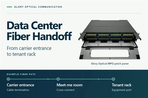
Map the building entry, first termination, meet-me-room patch field (if used), tenant rack and equipment port. Include every splice, adapter, cassette and patch cord. Mark fixed segments and routine moves. TIA-942-C covers single- and multi-tenant data centers; the project drawing and contract define the handoff points.

Do not use "carrier to rack" as the only route description. The entrance cable may be spliced into an ODF, patched across a shared meet-me room and then carried over a separate cable to a tenant panel. In another facility, a dedicated connectorized route may reach a tenant rack with fewer intermediate patch points. Those paths have different owners, connector counts and maintenance procedures.
A useful drawing includes the room and rack identifiers, panel positions, face and rear interfaces, cable route, service-loop locations, and the allowed access for each party. Add the provider handoff description exactly as contracted. A dotted line on a diagram becomes meaningful only when both sides can find the same physical adapter or connector in the field.
Separate the service boundary from the cable boundary
A demarcation can be contractual, physical or both. The provider may hand off a service at an optical port while the facility owns the cross-connect downstream. The tenant may own only the equipment cord inside its cabinet. Sometimes the facility operates a common patch field, yet the carrier retains responsibility for a circuit until a stated test point. The parties should record the arrangement rather than infer it from a rack label.
Write the boundary as a pair of named faces: "provider-facing port MMR-ODF03-P12" and "tenant-facing port TEN-R07-PP01-P08," for example. Then state whether those names identify a single fiber, a duplex pair or a multi-fiber connector. Record which party can disconnect each face, who cleans and re-inspects it, and who restores service when a patch cord is replaced.
| Record field | Question the drawing must answer | Example entry |
|---|---|---|
| Physical handoff | Which cabinet, frame, module and port can both parties inspect? | MMR-ODF03-P12, front LC duplex |
| Service identity | Which carrier circuit or tenant link uses the port? | Service ID from the approved order |
| Fiber path | Where do both fibers terminate, including intermediate patches? | MMR-ODF03-P12 to TEN-R07-PP01-P08 |
| Access and ownership | Who may patch or replace each component? | Facility patch field; tenant equipment lead |
| Test scope | Which two endpoints and method define acceptance? | Agreed panel faces in test plan rev B |
| Change record | Where will a later move or replacement be logged? | Port schedule and as-built revision |
These example identifiers are invented. The format matters less than consistency: the label on the cable, the test result and the as-built schedule must identify the same physical object.
Agree who can work at each face
A handoff record is useful during a fault only if it says who may open the rack and who may move the jumper. The carrier may have technicians in the meet-me room but no access to a tenant cabinet. The tenant may be able to replace an equipment cord but have no authority to reassign a carrier port. The facilities team may operate the shared patch field under a change ticket. Write these permissions beside the physical endpoints. Otherwise, a test plan can ask someone to disconnect a port they cannot legally or operationally reach.
Agree on the working sequence as well. Who provides an access window? Who identifies the affected circuit? Who takes the before and after photographs, if the operator requires them? Who checks the end face after a port is opened? A circuit can be restored quickly when the receiving party knows which rack face to inspect and which team can patch it. These are operational fields in the handoff schedule, not properties of a connector.
The service boundary may also move during a project. During construction, a contractor might deliver a tested fixed cable to an empty tenant panel. After service activation, the carrier may present an optical service at a different face and the facility may own the intervening patch. Keep the construction acceptance and live-service handoff as separate records. Give each a date and drawing revision so a later report is not mistaken for the state of the active circuit.
Choose the passive arrangement for the work it must support
A colocation operator may keep a centralized cross-connect so new carrier-to-tenant services can be assigned at a managed patch field. This adds connections and requires a loss allowance, but it keeps frequent moves away from active equipment. Fluke Networks describes this operational reason for a cross-connect and distinguishes it from an interconnect panel located beside the equipment.

Carrier cable ending in a splice ODF
Use a termination frame suited to the incoming cable when the route ends in loose fibers that need splicing, protection and controlled slack. The front adapter field can become a stable presentation point. From there, an approved patch route reaches the meet-me-room cross-connect or tenant path. An ODF purchase must state splice-tray capacity, cable entry, strain relief, adapter loading, front access and labels. "72 ports" by itself does not say whether the supplied panel is loaded, or which connector polish and pigtails are included.
Measured pre-terminated route into rack panels
A pre-terminated MPO or LC trunk is attractive when the route length and access points are known. The order then specifies the actual head dimensions, pull protection, end fanout lengths, fiber type, connector gender and polish, and a complete fiber map. At the rack, an adapter panel may retain MPO interfaces or a cassette may present LC duplex ports. Confirm that the protected connector head can pass the pathway and that the final panel has space for the rear cable and service loop.
ODF followed by a modular equipment transition
Some routes need both functions. The outside cable ends at an ODF; a connectorized trunk then serves tenant-side modular panels. This is useful when the external cable construction and the equipment-facing patch scheme differ, or when the tenant is likely to change equipment without touching the provider entry. The additional mating points belong in the loss calculation and test plan. The MPO-to-LC cassette or breakout is selected against the approved port map, not by the speed printed on a switch.
Decide whether a shared cross-connect earns its connections
A shared patch field has a purpose when carriers and tenants change independently. The facility can prepare the provider and tenant sides as stable fixed paths, then make an approved service assignment at the accessible cross-connect. A new tenant order may require a labeled jumper and a port-schedule update rather than a new cable pull through occupied racks. That workflow is especially useful when the operator must control who enters each cage.
The extra patching position also has a cost. It occupies rack space, adds mated end faces and requires a maintenance procedure. If a dedicated tenant rarely changes its carrier route and the optical budget leaves little room for another connection, an interconnect arrangement may be simpler. Count the actual connector pairs in each proposed route and ask the operator how often the assignment will change. The choice should follow the expected work, not a catalog picture of the densest frame.
Avoid a false shortcut in the drawing. "Cross-connect" should identify the two patch fields and the jumper between them; it is not a box that magically changes an optical interface. If one side is SC/UPC and the other is LC/UPC, show the appropriate patch cord. If one side is MPO and the other LC, show the approved breakout or cassette map. If the two ends differ in fiber type or polish, the design needs a separate technical review before parts are ordered.
An ODF and a patch panel can have overlapping names
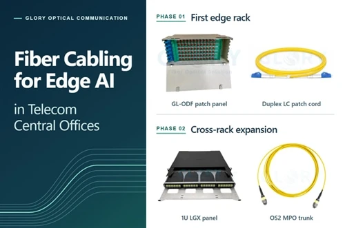
Product labels are a poor substitute for an assembly drawing. Glory Optical lists an Optical Distribution Frame with splice and distribution functions and a 72-fiber SC configuration. It also lists a GL-1U-4LGX/MPO rack model described as a 1U enclosure for four 24-fiber cassettes and up to 96 fibers. Both appear within the patch-panel range, although their internal jobs differ. A proposal must specify the exact model and the supplied loading rather than assuming every "ODF" has splice trays or every "patch panel" accepts the same cassette.
The Glory 2U MPO Patch Panel page describes a 19-inch sliding LGX platform and an upper capacity of 192 fibers in a listed configuration. That figure is a fiber capacity, not 192 conventional two-fiber circuits. If all 192 fibers were presented as duplex pairs, the nominal upper count would be 96 circuits, subject to the actual loaded module and port drawing. Rack density also has a service cost: a drawer must open, labels must remain visible, and a technician must reach the latches without loading neighboring connectors.

Ask for the front and rear elevations, module part numbers, cable-entry arrangement and populated-port map. A cassette that shares the word "LGX" with a frame is not automatically interchangeable. Glory's GL-07 box, for example, has a stated 24-fiber capacity, two MPO adapter positions and twelve LC duplex adapter positions in one configuration. Its dimensions and mounting fit must be checked against the proposed carrier; this article does not treat it as a drop-in module for the 1U rack model.
Make the rack layout part of the acceptance drawing
A panel can meet its published port count and still be awkward in the intended cabinet. Record the clear depth behind the rails, the position of rear cable managers, the path of the incoming trunk and the space needed to open a drawer. Check with the door closed as well as with the tray extended. The cable should have a supported route in both positions, with its minimum bend radius maintained under the actual assembly limits.
At the front, the technician needs room to read a label and release one connector without pulling its neighbors. A dense LC field may benefit from a specified pull-tab cord, but the tab is not a substitute for a workable patching layout. At the rear, reserve places for the strength-member anchorage or cable restraint, fanout transition and any service loop. Do not place a loose coil behind a drawer that must be withdrawn for maintenance.
The quotation should name an empty chassis, a chassis with adapters, or a fully loaded and tested assembly. These can have the same external photograph and very different bills of materials. For a model that offers four cassette positions, state which are populated at handover, which are protected with blanks, and whether spare modules are purchased or merely planned. The installer should receive the same loading drawing that purchasing approved.
Work through one tenant request before building the bill of materials
Return to the twelve-duplex-link request. A conventional duplex circuit uses two fibers, so twelve links require 24 active fiber paths. That is the only quantity that can be calculated from the service count alone. The number of MPO trunks depends on the populated fibers and mapping of each MPO interface. A 12-position ferrule may carry twelve active fibers in a duplex distribution design, or fewer active positions in a particular parallel-optics application. The chosen equipment interface decides the map.
Suppose the facility elects to present twelve LC duplex ports at the tenant panel and has approved a matching 24-fiber cassette at each end of a dedicated path. If the cassette drawings specify two fully populated 12-fiber rear MPO interfaces each, the 24 paths could be carried by two compatible 12-fiber trunks. This is a capacity example, not a released part list. The supplier still needs the cassette's actual rear interface, polarity, pinning, cable lengths, fire rating, panel fit and loss specification.
| Planning quantity | Illustrative count | What remains to verify |
|---|---|---|
| Requested duplex circuits | 12 | Both ends use two-fiber duplex optics |
| Active fiber paths | 24 | Service order and A/B fiber assignments |
| 24-fiber cassette positions | One at each end | Actual loaded model and front/rear map |
| 12-fiber MPO trunk groups | Two, if fully populated | Connector, polarity, pinning, length and routing |
| Tenant equipment cords | 12 at tenant end | Optical module receptacle and polish |
If the carrier delivers SC ports, the facility cannot solve the mismatch by describing the tenant route as "MPO-ready." It must name the intermediate patch cord or splice and include its interfaces in the drawing. If the tenant changes to a parallel 400G or 800G optic, revisit the active fiber positions and physical connector before reusing the same trunks. Cisco publishes 400G FR4 equipment with duplex LC and DR4 equipment with MPO-12; its 800G DR8 family includes dual MPO-12 and MPO-16 variants. Those examples show why a speed label cannot define the passive cable.
Reserve capacity at both ends of the route
Suppose the tenant later asks for another twelve duplex circuits. The new total is 24 circuits and 48 active fibers. If the first installation used a four-position 1U frame but populated only two 24-fiber positions at each end, the remaining two positions may have enough nominal module capacity. That does not mean another 24-fiber route is waiting behind the panel. The extra fibers must exist in installed trunks or be pulled, terminated and tested. The front ports and the backbone are separate inventories.
Conversely, spare fibers inside an installed trunk do not create usable LC ports until compatible modules or adapters are available at both ends. Document the reserve in three columns: fibers installed but dark, module positions unpopulated, and spare hardware held in stock. This stops the same capacity from being counted twice. A route that is physically full while the rack face looks half empty is common enough to deserve its own line in the expansion plan.
If the tenant pays for independent A and B services, prepare two route schedules. Two trunks in the same tray, cabinet entry or panel do not by themselves establish route diversity. Ask the facility which portions must be separate and document the actual pathways and termination points. The supplier can label and package the assemblies as A and B, but the operator must approve the physical separation. Keep the port and test records separate so a maintenance action on one path does not silently change the other.
Follow the loss through the complete route
The same twelve-link design might include an entrance splice, an ODF adapter, a cross-connect jumper, a trunk, a tenant cassette and an equipment lead. The short cable length does not make the connector losses disappear. Mark each mated connection on the channel drawing, then use the allowed loss and reach from the exact optical modules at both ends. Include fiber attenuation, splices where present, planned connections and a project margin. Record whether a quoted component value describes one connector, one mated pair, a cassette path or the complete factory assembly.
For a first-pass worksheet, write "route A, 180 m OS2; entrance splice count per drawing; ODF pair count; cross-connect pair count; tenant cassette path; equipment cords; reserve." Leave the numeric cells blank until the manufacturer data and optics are approved. That is more honest than copying a single catalog "low-loss" number into every row. The final acceptance limit comes from the project test plan and selected optical application, with the reference method and wavelengths stated.
The cross-connect is a real operational choice. It makes changes easier in a shared facility, while each additional patching point consumes part of the channel budget and creates another end face to inspect. If the approved optical budget is tight, compare a direct interconnect path against the proposed cross-connect path before ordering hardware. Do not remove a required access point merely to make a spreadsheet pass; resolve the architecture with the operator and equipment owner.
Test the link the owner will receive
A factory test report describes the assembly that the manufacturer tested. It cannot describe a new mated connection made after installation, a cassette added at the rack, or damage during a pull. Fluke Networks explicitly advises field testing of pre-terminated MPO cabling after installation. The contract should say whether acceptance concerns a trunk assembly, the installed fixed link between panels, or a channel that includes specified patch cords.
For a facility handoff, mark both endpoints on the drawing before choosing the test setup. A provider may test to its meet-me-room face while the facility tests the installed route to the tenant panel. The tenant may then verify the complete service with equipment. These records answer different questions. Keep each report with its own endpoint names, fiber positions, reference method, wavelengths, limit source and date. A "pass" file without a traceable pair of ports is hard to use during restoration.
Inspect the connector end faces before first mating and after a change where exposure could introduce contamination. Then verify polarity and measure insertion loss over the agreed passive boundary with an optical loss test set. The FOA lists inspection, loss measurement and polarity as common premises-cabling deliverables. If the project requires OTDR traces, specify their role separately; an OTDR event trace does not automatically replace the end-to-end loss result.
Plan the checks in the order the hardware is handled
At receiving, compare each supplied assembly against the approved part number and revision. Count the connectors and fanout legs; check the labels and protective caps; match its factory report to the serial or batch identifier. Do this before the installer moves the cable into a shared pathway. A wrong length or interface caught at receiving has a different schedule cost from one discovered after the route is closed.
During the pull, use the approved protection and tensile path for the finished assembly. Support the cable before removing the protective head and dressing its leads into the rack. Inspect the end faces once they are accessible, clean if required, and re-inspect before mating. Then verify each pair or required MPO position against the approved map. A continuity result can identify a path, but it is not an insertion-loss acceptance result.
After the panels are loaded, measure between the two endpoints defined for the installed link. If a result fails, isolate the path in a sensible order: confirm the test reference and endpoint labels, inspect accessible connections, compare the affected fibers with the map, and only then open a protected assembly or disturb a shared patch field under the operator's procedure. Record the corrected port and retest the agreed boundary. A successful link-light check can accompany commissioning, but it should not overwrite the passive cabling report.
Keep the first accepted result as a baseline. When a tenant asks for a new cross-connect months later, the changed patch cord and newly mated surfaces may need inspection and verification. The original factory trunk report remains useful for the trunk, but it cannot describe the new complete channel. The change ticket should identify which evidence was repeated and which fixed link was left untouched.

Give the next technician a usable record
A cross-connect will change. The owner may move a circuit to a different carrier port or replace a tenant switch. The record therefore needs more than the original drawing. Retain the current front-port assignment, the fixed cable route, the patch-cord identifier, the optical module model and the test report for the last accepted condition. Log a change when a cord is moved, rather than waiting for a fault to reconstruct the path.
Place labels where they remain visible after the rack is dressed. Do not put a cable tag on a bend that prevents the drawer closing, or hide a cassette number behind a bundle. The rear route should be supported so a technician can slide a tray without transferring load to the MPO or LC connector. A spare assembly is useful only if its fiber type, polish, gender, polarity, length and approved drawing revision match the installed route.
The paper trail can be compact. One page per link group can carry the circuit IDs, A and B endpoints, trunk and module part numbers, a drawing revision, and report filenames. Keep the approved baseline and later change history separate. A future contractor should be able to find a failed duplex pair without guessing which "Port 12" a prior team meant.
Write a restoration note before a fault occurs
The maintenance file should show the last known working patch at the meet-me room, the tenant-facing port and the approved spare assembly. Add the route drawing and the location of the last valid passive loss result. When a service fails, the team can compare the active equipment alarm with the known passive boundary and decide which party is authorized to test next. That sequence saves the shared patch field from exploratory unplugging.
A spare jumper has to match more than its connector silhouette. Check fiber grade, polish, duplex orientation or MPO position map, pinning, length, jacket and the intended port labels. Store the replacement with its configuration record. If the operator permits temporary restoration on another port, log the temporary pair assignment and set a clear point for transferring the circuit back to its permanent record. The as-built schedule should show the present state, including a temporary state that has lasted longer than planned.
Approve one complete build before repeating it
A colocation project often repeats a small set of cable and panel combinations across many racks. That repetition is useful only after the first combination is proven to fit. Ask for an approved sample or first article with the intended panel, cassette, trunk and equipment lead. A loose connector sample on a desk cannot show whether a drawer closes on the finished fanout or whether the labels remain readable with every neighboring port occupied.
Start with the drawing. It should show which side of an MPO connector is being viewed, where key-up or key-down orientation applies, which positions are populated, and how they reach the LC ports. Compare that drawing to the actual assembly and the port schedule. If a sample exposes a mapping error, revise the drawing and part number before bulk production. A verbal instruction to "wire the rest like the sample" is difficult to audit after the sample leaves the site.
Then put the assembly in the rack it is intended to serve. Check the mounting holes and depth, rear clearance, strain relief, front-port access and cable manager. Open and close the drawer with all planned cords in place. Verify that the cable can be dressed to its assigned rack without pulling a connector when the door closes. Record any changed fanout length or mounting bracket position on the release drawing. Those small dimensional choices are what make repeated production useful to installers.
Finally, compare evidence at the same level of detail as the product. An approved panel photograph confirms appearance and broad loading; it does not prove optical polarity. A connector test sheet can establish the component result under its stated reference method; it does not cover a new mating in the room. Ask the supplier to identify the tested object, serial or batch, wavelengths, measurement boundary and limit source. Keep the first installed-link test beside the factory record so a later technician can separate a delivered assembly problem from a site connection problem.
When the first article passes, freeze the interfaces and labeling scheme for the repeat order. Allow substitutions through a documented review. A different cassette footprint, connector polish or cable jacket can alter compatibility even when the catalog calls the item by the same generic name. For staged construction, record which drawing revision each rack received. That makes expansions and spare ordering straightforward without pretending every rack was built in the same week.
What to send with a quotation request
Send one route sketch and one port schedule before asking for prices. The commercial quote can then identify a real assembly, not a loose category such as "1U ODF plus MPO cable." Glory Optical's data-center solution page describes this configuration approach: equipment interfaces, route schedule, port count, performance requirement and handover evidence are separate inputs to the production bill of materials.
- The service order and physical handoff: carrier and tenant locations, exact panel faces, access rules and party responsible for each segment.
- Optical interfaces: switch and transceiver part numbers, PMD, connector receptacles, active fiber positions, polish and required breakout mode.
- The route: measured pathway, rack positions, expected service loops, permitted pull direction, head clearance and finished assembly length datum.
- The panel and ODF loading: model, rack units, splice tray if needed, cassette format, front and rear adapters, populated ports, blank positions and maintenance clearance.
- The cable build: OS2 or specified multimode grade, fiber count, MPO pinning and polarity or full map, jacket rating, fanout length, strain relief and labels.
- The acceptance package: component test scope, field endpoints, loss limit source, inspection criteria, reporting format and as-built identifier.
Ask the supplier to return an assembly drawing and a line-by-line bill of materials. If two quotations differ, check whether one includes loaded modules and equipment cords while the other prices an empty chassis. Confirm a first article against the rack and port schedule before repeating a custom build across many cabinets.
A later tenant move shows whether the record works
Imagine that the tenant replaces a switch six months after the original handoff. The incoming carrier service remains on the same meet-me-room port, but the new switch sits one cabinet farther away. The old equipment lead will not reach. The request sounds like a small patching job. It is a useful test of the original documentation because the technician must determine what can move without disturbing the carrier-facing route.
First, the work order identifies the service and both current endpoints. The operator checks whether the fixed tenant link ends at a rack panel that can serve the new switch through a longer, correctly specified equipment cord. If so, the fixed trunk and the meet-me-room jumper may stay in place. The replacement cord must match the optical module interfaces, fiber type and polish, with enough supported length to reach the new position. The new cord label and the updated port schedule should be prepared before the maintenance window.
If the new cabinet has its own panel, the operator may instead assign a different tenant-side fixed link at the cross-connect. That changes the physical path. The ticket should name the old and new patch positions, identify which existing test result applies to the newly selected fixed route, and call for inspection and verification of the changed connections. If no tested fixed path reaches the cabinet, the job is a new cable installation. A longer jumper draped across doors is not a substitute for a planned route.
During the work, the technician verifies the destination labels at both faces before unplugging anything. The facility's access rules decide who may move the shared jumper. The cable plant is inspected and tested over the boundary named in the change plan; the active service is then checked by the equipment owner. When the new port is accepted, the as-built record changes to show it as current. The old port can be marked free only after the operator confirms no other circuit depends on that jumper.
This example is deliberately ordinary. Nothing failed at the factory and no unusual component is needed. The value of the ODF, rack panel and cross-connect lies in having stable, reachable places to make this change while preserving a traceable path. A reader should be able to look at the final drawing and answer the practical question: if this service moves again, which exact connector may be touched, by whom, and what must be retested?
Questions that come up during handoff planning
Can the carrier handoff be inside the tenant rack
It can be if the facility agreement and access rules allow that location and both parties accept the named port as the boundary. A shared meet-me room may be easier to operate when carrier changes are frequent. The contract and the site drawing decide the answer.
Does a 96 fiber ODF provide 96 duplex tenant links
No. Ninety-six individual fibers can support up to 48 conventional two-fiber duplex paths before reserves and other allocations. The actual circuit count depends on the loaded adapters, module mapping and selected optical interfaces. A 96-fiber figure must not be read as 96 duplex circuits.
Should a pre-terminated MPO trunk end directly at equipment
Direct connection can work on a stable, accessible route with a matching equipment interface and enough loss headroom. A managed panel is often preferable where moves are frequent or where the permanent route needs protection from equipment replacement. Confirm the complete channel either way.
Does a factory report complete the site acceptance
It documents the factory assembly at the time and boundary of that test. The installed link may add adapters, cassettes and handling risk. The site acceptance plan should state the installed endpoints and required measurements.
Can a 1U rack ODF replace a carrier splice frame
Only if the specified build has the necessary cable entry, splice management, slack capacity and approved access. Glory's listed GL-1U-4LGX/MPO model is a four-cassette rack platform. Do not assume it performs the same job as a splice-oriented ODF merely because both products use the term ODF.
The decision to make before the purchase order
Choose the handoff point with the facility operator and carrier. Once it has a name on the drawing, the passive route becomes a sequence of checkable choices: what terminates the incoming cable, where changes will be made, which interfaces the tenant equipment uses, and how the finished route will be accepted. An ODF, cross-connect and rack panel can all belong in the same design. Each one should have a stated job and a corresponding line in the port schedule.
For a project review, send Glory Optical the carrier handoff description, rack layout, port list and required optical test boundary. The company can then configure the ODF or panel, MPO/LC assemblies and documentation against the same route rather than quoting components in isolation.