

Wireless / Outdoor Connectivity
For base station fiber access, RRU / AAU connection, rooftop sites, tower-top equipment and outdoor remote radio fiber links. Glory Optical configures the passive path with indoor patching, outdoor feeder cable, splice protection and pre-terminated weatherized assemblies matched to the actual equipment interface.
Glory Optical solution scope
One passive fiber package from the DU / BBU room to each radio port
We turn the equipment list and site route into a controlled passive BOM instead of quoting unrelated cables, boxes and connectors.
Scope boundary: Glory supplies the passive fiber connection layer. DU / BBU equipment, RRU / AAU hardware, optical modules, fronthaul switching, WDM equipment and timing or synchronization systems remain operator- or integrator-selected. Their specifications become inputs to the passive BOM.
Passive FTTA path
Four controlled zones between the indoor port and tower-top equipment
Each zone has different mechanical, environmental and interface risks. Keeping them separate makes the site BOM easier to verify before production.
DU / BBU Room
Optical module → LC patch cord → ODF or patching position.Confirm module receptacle, UPC / APC, duplex mapping, rack location and indoor fire requirement.
Tower Base / Building Exit
Indoor-outdoor transition → feeder entry → optional splice or junction closure.Map cable outside diameter, entry seal, strength member, grounding and service access.
Tower / Rooftop Route
OS2 outdoor feeder cable → approved support hardware → protected service loop.Select fiber count, dielectric or armored construction, UV exposure, water blocking and route length.
RRU / AAU Interface
Pre-terminated outdoor assembly → model-specific weatherized radio port.Verify housing geometry, keying, sealing state, cable diameter, bend control and strain relief.
A conventional CPRI or eCPRI radio link remains point-to-point at the passive layer. A terminal may organize separate fiber pairs, but a standard PLC splitter is not an Ethernet switch or fronthaul multiplexer and is not inserted to share one link among several radios.
Core product portfolio
Real Glory products mapped to the passive FTTA path
Published models are starting points. Final interface, cable, sealing, capacity and report fields are frozen in the approved project configuration.
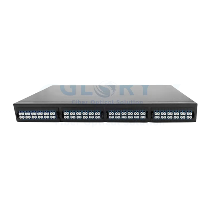


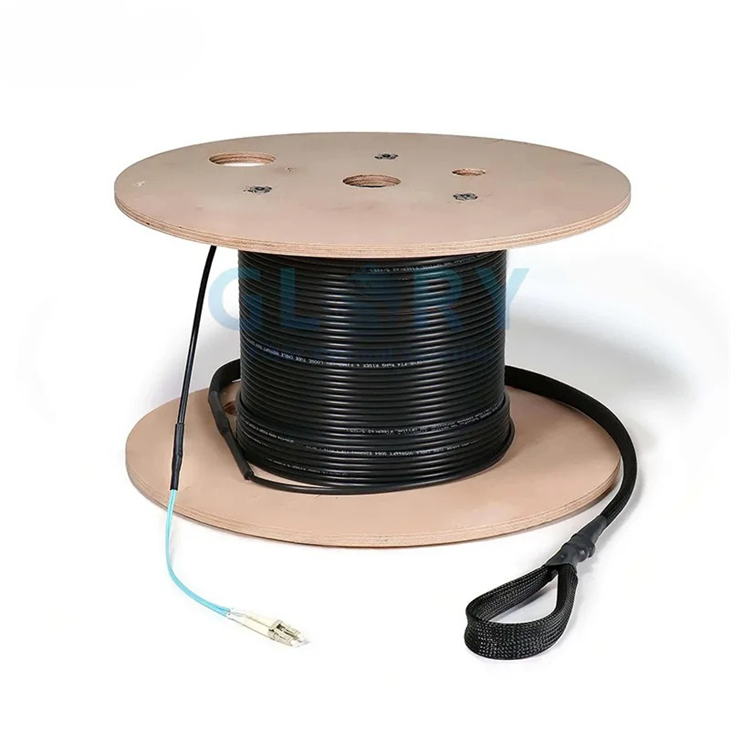
Product-page values describe listed configurations, not universal FTTA limits. The quotation and approved drawing control the delivered connector, mated-state ingress rating, fiber, cable construction, length, temperature range and test record.
Our configuration method
How Glory turns a site schedule into a production BOM
The process starts with radio interfaces and actual routing conditions, then resolves them into passive components and acceptance evidence.
| Project input | What Glory checks | Release output |
|---|---|---|
| Radio and optical-module list | Port geometry, receptacle, polish, fiber pair, optical reach and vendor drawing | Approved interface schedule |
| Sector and radio count | Current fiber pairs, redundancy, additional bands and planned expansion | Fiber-count and port map |
| Measured route | Indoor and outdoor lengths, transitions, access points, bends and service-loop locations | Cable cut-length and route schedule |
| Tower or rooftop environment | UV, water, salt, temperature, lightning strategy, metal-path restrictions and support method | Cable, closure and mounting specification |
| Connection-loss requirement | Fiber attenuation, connector pairs, splices, passive transitions and agreed engineering margin | Passive loss worksheet |
| Acceptance package | Identifiers, IL / RL fields, end-face inspection, continuity, OTDR and as-built records | Approved test and labeling format |
Maximum fronthaul distance is not assigned by G.652.D or G.657 fiber alone. It follows the selected optical modules, complete passive loss, functional split, transport design, latency and synchronization requirements. Glory uses the approved equipment reach as an input rather than publishing one universal distance.
Deployment models
Three common ways to configure the passive FTTA path
The radio architecture and route decide the fiber count and passive topology-not a generic 4G or 5G label.
Testing and evidence
Product records first, installed-link acceptance second
Factory documentation verifies the supplied passive components. Field commissioning verifies the finished link after transport, routing, splicing and mating.
| Reference | Correct use on this page |
|---|---|
| eCPRI Specification v2.0 | Fronthaul interface and transport context; it does not certify a passive cable assembly. |
| ITU-T G.652 / G.657 | Single-mode fiber characteristics and bend-insensitive fiber categories; not a universal DU–RU distance limit. |
| IEC 60529 | Ingress-protection classification. The product configuration and whether the interface is mated must be stated. |
| IEC 61300-3-35:2022 | Visual inspection of connector and transceiver end faces using the applicable connector and zone criteria. |
| IEC 60794-1-21 / IEC 60794-1-22 | Mechanical cable test methods / environmental cable test methods. The exact test and edition belong in the approved specification. |
| Telcordia GR-326 / GR-771 | Connector-assembly / splice-closure qualification references only when required and supported by product-specific evidence; not blanket company certification. |
Project workflow
From radio schedule to tested delivery
Project request
Information that helps us quote the correct FTTA connection package
A radio list and route sketch are enough to begin. Glory can identify the remaining interface and construction decisions before sample approval.
Equipment
DU / BBU, RRU / AAU and optical-module manufacturer and model
Interfaces
Port drawings, connector housing, keying, UPC / APC and mating-side details
Site Count
Sectors, radios per sector, current fiber pairs, redundancy and expansion reserve
Route
Tower or building height, actual path length, transitions, bends and access points
Environment
UV, coastal salt, temperature, rainfall, lightning strategy and mounting method
Acceptance
Loss limits, end-face inspection, OTDR, labels, reports and packaging sequence
Frequently asked questions
Working with Glory Optical on FTTA projects
Q: What does Glory Optical supply for a 5G FTTA project?
A: Glory supplies the passive fiber connection layer: indoor ODF and LC patching, outdoor feeder cable, splice protection and pre-terminated weatherized cable assemblies for RRU or AAU ports. Active radios, DU or BBU equipment, optical modules, Ethernet switching and synchronization systems remain project-selected equipment.
Q: Which FTTA connector fits Huawei, Ericsson or Nokia radio equipment?
A: Connector selection is radio-model specific. DLC-style, FullAXS, ODC, NSN-style and other weatherized LC interfaces can differ in housing geometry, keying, sealing and cable diameter. Glory confirms the radio model, port drawing and mating interface before releasing a cable assembly.
Q: Can a PLC splitter or standard split MST distribute one eCPRI fiber to several radio units?
A: Not in a conventional point-to-point CPRI or eCPRI link. Each radio connection normally uses its assigned fiber pair or an operator-engineered transport system. A passive terminal may organize separate fibers, but a standard PLC splitter must not be inserted as though it were an Ethernet switch or fronthaul multiplexer.
Q: How many fibers are needed for a three-sector FTTA site?
A: There is no universal count. A simple three-sector site with one duplex optical link per radio uses three fiber pairs, while additional bands, radios, redundancy and growth increase the requirement. Twelve-fiber or twenty-four-fiber feeder configurations are common planning options, but the final count follows the radio and expansion schedule.
Q: What information is needed for an FTTA quotation?
A: Send the radio and optical-module models, port drawings, sector and radio counts, route lengths, tower or rooftop layout, required fiber reserve, mounting and environmental conditions, cable construction, test limits, labeling and rollout quantities. Glory uses these inputs to prepare a configuration-based passive BOM.
For engineering background and component-selection detail, continue to the 5G FTTA cable, closure and connector guide. This Solution page remains focused on product configuration, project evidence and quotation.