Choose by the Optical Path, Not the Connector Name
Draw the path from the transmitting media-dependent interface (MDI) to the receiving MDI. That drawing reveals the correct starting architecture.
| End-to-end topology | Correct starting architecture | Decision reason |
|---|---|---|
| LC optic ↔ LC optic | Duplex LC cable | Both endpoints already use one transmit and one receive fiber. |
| Parallel MPO optic ↔ four or eight duplex LC optics | MPO to LC breakout cable | Valid after the optic and switch are confirmed to support that breakout mode and lane map. |
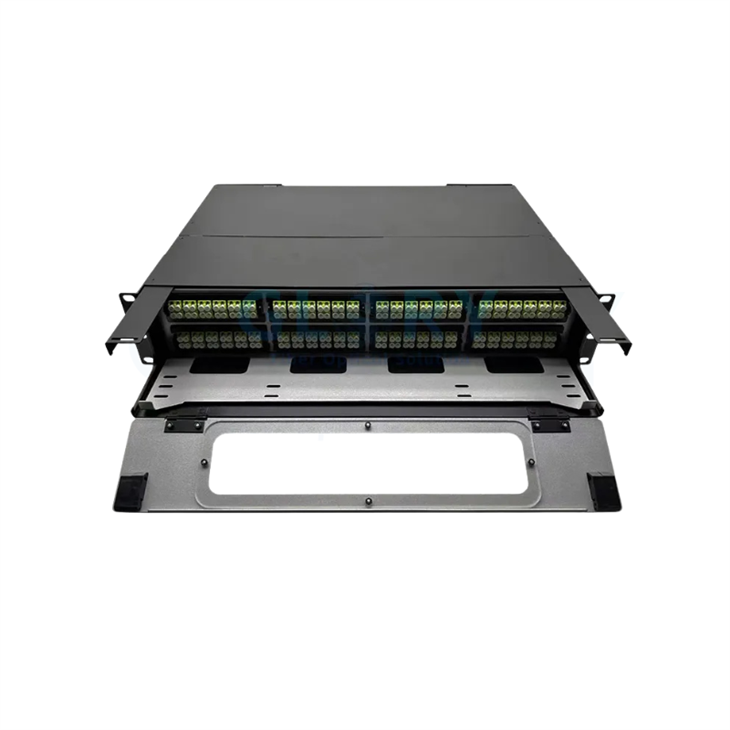
| MPO backbone ↔ LC equipment edge with frequent moves, adds and changes | MPO trunk + cassette or patch panel + duplex LC cords | The panel gives technicians front access and one-circuit patching. |
| Native MPO optic ↔ native MPO optic | MPO-to-MPO jumper or structured MPO trunk | The path stays parallel from end to end; an LC transition adds no value. |
What an MPO to LC Breakout Cable Actually Does
An MPO-to-LC breakout cable-also called an MPO-to-LC harness, fan-out cable or MTP LC harness cable-routes individual fibers from one multi-fiber connector to identified LC channels.
One shared body, several duplex channels
The MPO-format end carries multiple fiber positions. At the other end, LC connectors are grouped into duplex channel pairs and labeled for their destinations. The approved drawing defines which MPO position reaches each LC fiber.
One cable body, one circuit
A duplex LC cable carries two fibers between two LC endpoints-one transmit and one receive fiber in a conventional duplex link. Each assembly remains independently routed, tested and replaceable.
Lane routing and optical splitting solve different problems
A breakout harness preserves separate physical fibers. A PLC splitter divides optical power from an input among several outputs. Signal channelization must already exist in the optic and host port; the passive harness transports the assigned lanes to their destinations.
For cable-family definitions, review Glory's guide to MTP/MPO trunk, breakout and conversion cable types and the distinction between MTP and MPO connectors.
Verify the Transceiver PMD and Port Breakout Mode
Check the complete switch-port and transceiver part numbers at both ends before comparing cable prices.
Identify the PMD
Record the Ethernet optical PMD, specified reach, fiber medium, wavelength and far-end compatibility.
Read the optical MDI
Confirm the receptacle, polish, active fiber positions and pinned or unpinned interface.
Approve channelization
Confirm that the host platform, port, software mode and selected optic support the required breakout.
40G SR4 to 4 × 10G: the SKU can change the answer
A compatible parallel 40G SR4-family module uses four transmit and four receive lanes. When the switch supports 4 × 10G mode and the far end presents four compatible 10G duplex optics, an eight-active-fiber MPO-to-4×LC-duplex harness is a valid architecture.
A documented model-level exception
Cisco's 40GBASE QSFP module data sheet states that QSFP-40G-SR4-S does not support 4×10G breakout connectivity, while QSFP-40G-SR4 and QSFP-40G-CSR4 do. Modules in the same broad speed and form-factor family can therefore require different cabling decisions.
Breakout is valid when
- The module exposes a parallel MPO optical interface.
- The switch enables the required 4 × 10G port mode.
- The far end uses four compatible 10G duplex optics.
- Eight active fibers follow the approved Tx/Rx map.
Use another path when
- Native parallel MPO optics face each other: use MPO-to-MPO.
- Both optics expose duplex LC: use duplex LC.
- The host lacks channelization: a passive cable cannot add it.
100G SR4 to 4 × 25G
A supported 100G SR4-to-4 × 25G application also uses four transmit and four receive lanes, mapped to four duplex SFP28 channels. Approval still covers the exact 100G module, host breakout configuration, far-end optics, reach and FEC requirements. Replace the ambiguous BOM line "QSFP28 to four LC" with exact module SKUs and the intended port mode.
400G DR4 breakout versus 400G FR4 over duplex LC
| 400G optical interface | Optical structure | Typical cable starting point |
|---|---|---|
| DR4-family parallel optic | Four single-mode transmit/receive lane pairs on a parallel MPO interface | When the platform supports it, an MPO-to-LC breakout can feed four 100G DR1 duplex links. See Cisco's 400G QSFP-DD data sheet. |
| FR4 wavelength-multiplexed optic | Four wavelengths carried over one duplex single-mode fiber pair | Duplex LC. Cisco lists a duplex-LC 400G FR4 module in its 400G QSFP data sheet. |
Match Active Fibers to LC Duplex Channels
State the physical MPO ferrule format and the active-fiber map separately. "MPO-12" can describe a 12-position ferrule even when an application uses eight positions.
| Physical format or system | Active fibers | LC duplex channels | Design use |
|---|---|---|---|
| MPO-12 ferrule with eight active positions, or project-specific MPO-8 | 8 | 4 | Supported four-lane parallel breakout such as 40G→4×10G, 100G→4×25G or 400G→4×100G |
| MPO-12 with every position active | 12 | 6 | Six duplex circuits in a structured distribution path |
| MPO-16 with every position active | 16 | 8 | Eight-lane breakout or distribution with a matching MDI and map |
| MPO-24 with every position active | 24 | 12 | High-density duplex distribution, commonly through trunk and panel architecture |
8 active → 4 LC duplex
Four circuits use eight fibers. In a 12-position SR4-type ferrule, four central positions may remain inactive.
12 active → 6 LC duplex
A fully active 12-fiber distribution harness can carry six independent duplex circuits. This differs from a four-lane QSFP breakout.
16 active → 8 LC duplex
Confirm whether the equipment presents MPO-16, dual MPO-12 or another interface before releasing the assembly drawing.
Approve Polarity, Pinning, Polish and the End-to-End Lane Map
Mechanical fit confirms only part of compatibility. The channel also depends on alignment pins, key orientation, fiber sequence and end-face geometry.
Evaluate polarity at channel level
Type A, B and C describe assembly-level fiber mapping. Adapters, trunks, cassettes, patch cords and equipment MDIs can change the complete Tx-to-Rx relationship.
The acceptance question is simple: Does each source transmitter arrive at the intended destination receiver?
Use Fluke Networks' fiber polarity guide as a system-level reference.
Verify every physical interface
- One side of each normal MPO mated pair is pinned and the other unpinned.
- MPO format and fiber positions match across every adapter.
- UPC/PC and APC interfaces follow the optic and infrastructure documentation.
- Source position, LC leg, Tx/Rx role and destination port appear on the drawing.
For commissioning faults, Glory's MPO dark-link troubleshooting guide follows a controlled sequence: verify physical mating, reconstruct the end-to-end map, then inspect and test.
MPO to LC Breakout Cable vs Duplex LC Cable
The strongest choice balances density, serviceability, loss and installed cost for the same number of live circuits.
| Factor | MPO to LC breakout cable | Duplex LC cable |
|---|---|---|
| Best fit | One verified parallel MPO or distribution interface feeding several LC channels | One LC endpoint connecting to another LC endpoint |
| Main-route density | Shares one cable body among 4, 6 or 8 duplex channels, depending on active fibers | Uses one cable body per duplex channel |
| Port breakout | Available when the optic and host explicitly support channelization | Preserves the native duplex link presented by the optics |
| Moves, adds and changes | Fixed branch relationships favor stable port maps | Each circuit moves or changes independently |
| Failure/replacement domain | One assembly can serve 4–8 circuits | Normally one circuit per assembly |
| Polarity management | Requires active positions, lane map, keying and mating to align | A-to-B duplex polarity is easier to audit |
| Inspection and test | Inspect the multi-fiber end face and certify every active lane | Inspect and test one duplex pair at a time |
| Installed-cost profile | Can reduce shared-route bodies and intermediate hardware in stable high-density builds | Often economical for small, simple or frequently changing LC-to-LC deployments |
Normalized route-body reduction
One eight-active-fiber harness consolidates four duplex cable bodies into one along the shared route-a 75% reduction. Twelve active fibers consolidate six bodies into one (83.3%), while sixteen active fibers consolidate eight into one (87.5%).
These percentages describe shared-route cable bodies. They do not claim the same reduction in labor, pathway area or installation time.
Replacement-domain trade-off
A fault on one branch may leave other channels operating, but replacing the complete harness can require a maintenance window for every attached circuit. Duplex LC keeps the normal replacement unit at one circuit.
For critical services, stock a labeled spare with the same map and leg lengths, and confirm that attached circuits can share a maintenance event.
Direct Harness, MPO Cassette or Duplex LC?
Real projects often need a third architecture: an MPO backbone that transitions through a managed panel before reaching LC equipment ports.
Choose a direct harness
- One supported parallel port feeds known LC endpoints.
- Destinations stay in the same rack or predictable zone.
- Port relationships and leg lengths can be frozen.
- Fewer passive interfaces protect a tight loss budget.
Choose trunk + cassette
- Technicians need front-facing LC ports.
- Circuits change destination or ownership.
- The site uses structured cabling zones or cross-connects.
- Modular serviceability justifies extra mated pairs.
Choose duplex LC
- Both optics expose LC.
- The host does not use the required breakout mode.
- Each circuit needs independent routing and replacement.
- Uniboot construction can reduce cord bulk while preserving granularity.
For the managed transition, compare Glory's MPO patch panel with its discussion of cassette and cassette-less high-density architectures.
Loss Budget, Inspection and Per-Lane Testing
Calculate loss for the interfaces traversed by one active lane. Other LC branches do not add their connector loss to that channel.
Planning example
Using a conservative 0.4 dB per mated pair for early planning, two pairs allow 0.8 dB for connectors and four pairs allow 1.6 dB. Replace that planning value with the approved component maximum and the transceiver's actual optical budget.
This is a budgeting example, not a product performance guarantee.
Direct versus cassette path
A direct harness can remove intermediate cassette interfaces. A structured cassette path adds connection points and loss while improving access and modularity. Count the actual pairs for each active channel, then decide whether the operating flexibility earns its allowance.
Inspect–clean–inspect
Multi-fiber ferrules place several fibers on one end face, so contamination can affect one or several lanes and transfer during mating. Reference IEC 61300-3-35:2022 for the observation and classification of debris, scratches and defects.
- Inspect both mating end faces.
- Clean with the approved method when the end face fails the required criteria.
- Reinspect before mating.
- Protect unused connectors with clean dust caps.
Certify every active lane
Tier 1 acceptance records length, insertion loss and polarity on every active fiber or intended duplex channel. Add Tier 2 OTDR only when the project needs event-level characterization or fault location. The factory acceptance file should connect the assembly serial number, lane map, test wavelength, reference method, per-lane result, inspection status and applied limit.
A 48-Link Example: Density Versus Replacement Impact
This normalized model compares architectures for 48 duplex circuits sharing one pathway. It is a topology model rather than a price or labor benchmark.
| Architecture | Main shared-route cable bodies | LC duplex channels | Shared replacement domain |
|---|---|---|---|
| 48 individual duplex LC cables | 48 | 48 | 1 circuit per cable |
| Twelve 8-active-fiber MPO-to-LC harnesses | 12 | 48 | 4 circuits per harness |
| Eight 12-active-fiber distribution harnesses | 8 | 48 | 6 circuits per harness |
The eight-active-fiber option cuts the main-route body count from 48 to 12. The twelve-active-fiber distribution option cuts it to eight, while increasing the number of circuits that share one replacement unit.
Normalize every design to the same number of live circuits, route, test scope and service-life assumptions. Glory's custom fiber cable guide adds route-specific questions for drawings, lengths and replacement planning.
Glory Product Recommendations
Match each product family to the approved active equipment, lane map, route and operating model.




RFQ Checklist Before You Order
"MPO to LC cable, OM4, 10 m" leaves the key interoperability decisions unresolved. Include the following information in the RFQ and drawing package.
- Switch model and port number at each end
- Exact transceiver part number and PMD
- Native or breakout port mode, including software support
- Direct harness, trunk + cassette, or LC-to-LC topology
- MPO physical format and active fiber positions
- Required OM3, OM4, OM5 or OS2 fiber
- MPO pin state, key orientation, polish and end-to-end map
- LC type, polish, channel count, labels and leg lengths
- Routed length, service loop, jacket rating and bend limits
- Maximum IL/RL, wavelengths and reference method
- Per-lane report, serial traceability, dust caps and spare requirement
- Approved transceiver data sheets and rack drawing
Frequently Asked Questions
Q: Is MPO better than LC?
A: Each connector serves a different topology. MPO supports parallel optics and multi-fiber density; duplex LC provides an independently managed two-fiber circuit and remains common across several 10G–400G PMDs.
Q: Can MPO connect directly to LC?
A: The connector faces do not mate. An MPO-to-LC breakout cable or MPO cassette provides the transition by mapping individual MPO fibers to designated LC channels.
Q: Is an MPO to LC breakout cable an optical splitter?
A: It routes separate physical fibers and preserves their lane identities. Optical power division belongs to a splitter, while signal channelization belongs to the active optic and host.
Q: Can every 40G, 100G or 400G port use a breakout cable?
A: Breakout requires a compatible parallel optical PMD, active-lane map and host port mode. For example, Cisco documents 40G SR4-family SKUs with different breakout support, while 400G DR4 and FR4 use different optical interfaces.
Q: How many LC duplex channels come from MPO-12?
A: A 12-position ferrule with eight active positions commonly maps to four LC duplex channels. A fully active 12-fiber distribution harness maps to six. State active positions and channel count in the order.
Q: What polarity should an MPO to LC breakout cable use?
A: Approve the complete Tx-to-Rx map for the installed path. Cable Type B is common in parallel applications, while intermediate adapters, trunks and cassettes can change the channel-level requirement.
Q: When is a cassette better than a direct harness?
A: A cassette fits sites that need front-facing LC patching, individual circuit changes, modular serviceability or structured cross-connects. A direct harness fits stable port maps where fewer passive interfaces and fixed legs are valuable.
Q: How should the completed assembly be tested?
A: Inspect both mating end faces, verify the lane map, then record Tier 1 length, insertion loss and polarity for every active lane. Add OTDR when the project requires event-level characterization or fault location.