


A part number like "1x32 PLC LGX SC/APC" looks specific until you realize it omits the power distribution ratio, the fiber grade, the pigtail length, and the exact pigtail construction. Two splitters sharing that same abbreviated label can arrive at your dock as mechanically and optically different products. This article introduces a six-layer classification framework that decodes every fiber optic splitter into its independent properties, exposing the gaps that catalogs routinely leave unfilled.
Why "Splitter Type" Is a Broken Question
Ask a supplier "what type of splitter do you have?" and you will get one of six different answers depending on which dimension the salesperson happens to be thinking about. They might say "PLC" (answering the technology question), "1x8" (answering the topology question), "LGX" (answering the package question), or "SC/APC" (answering the connector question). Each answer is correct for its dimension and useless for the other five.
The problem is not that suppliers are being evasive. The problem is that "type" compresses at least six independent engineering decisions into a single word, and different catalogs make different compression choices. A buyer who compares two "1x16 PLC splitters" without checking all six layers may discover, after delivery, that one has bare 250-micron fiber pigtails while the other has 2.0 mm jacketed cable leads. Both are legitimately "1x16 PLC splitters." They are not interchangeable.
The framework below separates the compressed label back into its constituent layers. Each layer answers one question, requires one piece of evidence to confirm, and cannot be inferred from any other layer. Think of it as a normalized comparison record: before you approve a substitute, before you issue a purchase order, before you sign off on a field installation, every field in the record must be either stated, verified, or explicitly unresolved.
Layer 1: Technology, the Physics of Splitting
Two fabrication technologies dominate the fiber optic splitter market. Planar Lightwave Circuit (PLC) splitters are built using semiconductor-style photolithography on silica glass substrates, creating a precise waveguide circuit that splits light uniformly across all output ports. Fused Biconical Taper (FBT) couplers are made by physically twisting two or more bare fibers together, heating them until they fuse, then pulling them into a tapered region where light couples between the fiber cores.

Why the Technology Layer Matters More Than People Think
Most comparison guides stop at "PLC is better for high split ratios, FBT is cheaper for low ratios." That is true but incomplete. The technology choice has cascading implications for every other layer, implications that become visible only when you encounter them in the field.
PLC splitters operate across a flat wavelength range of 1260 to 1650 nm, covering every current and planned PON wavelength in a single device. FBT couplers are optimized for specific wavelengths, typically 1310/1490/1550 nm for GPON, and their coupling ratio shifts when used at other wavelengths. This means an FBT splitter that performs acceptably on a GPON network may fail on an XGS-PON network that uses 1270 nm upstream and 1577 nm downstream wavelengths, even though both standards are within the same physical fiber plant.
The maximum split ratio is also technology-dependent. A single PLC chip can achieve 1x64 or even 1x128 on one substrate. A single FBT taper junction is limited to 1x2 or 1x4; higher ratios require cascading multiple FBT couplers in a tree, which increases insertion loss, consumes more physical space, and accumulates excess loss at each junction. A 1x8 FBT splitter is typically three cascaded 1x2 couplers; a 1x32 FBT would require five cascade stages with exponentially compounding loss.
|
Parameter |
PLC Splitter |
FBT Coupler |
|
Operating Wavelength |
1260-1650 nm (flat) |
1310/1490/1550 nm (optimized) |
|
Max Split Ratio (single device) |
1x64 (1x128 possible) |
1x2 to 1x8 (cascaded) |
|
Insertion Loss Uniformity (1x8) |
+/- 0.5 to 0.8 dB |
+/- 1.0 to 2.0 dB |
|
Polarization Dependent Loss |
0.15-0.25 dB |
0.3-0.5 dB |
|
Operating Temperature |
-40 to +85 C |
-5 to +55 C |
|
Unequal Split Ratios |
Difficult / custom |
Easy and cheap |
|
Return Loss (APC) |
60+ dB |
50-55 dB |
|
Cost (1x2) |
Higher |
Lower |
|
Cost (1x32) |
Lower |
Higher (cascaded) |
The temperature range difference is not academic. An FBT coupler rated to -5 degrees Celsius will experience ratio drift and excess loss increase in climates where winter temperatures drop below that threshold. PLC splitters, with their solid-state waveguide construction, maintain stable performance across the full -40 to +85 degree range specified in Telcordia GR-1209. This is why most outdoor FTTH deployments have standardized on PLC technology regardless of split ratio.
But FBT retains one genuine advantage: unequal split ratios. Because the FBT coupling ratio is determined by the fusion pull length and can be monitored in real time during production, making a 10:90 or 5:95 coupler is straightforward and inexpensive. Making an unequal PLC splitter requires a custom mask design, which is economically viable only at volume. For tapping applications where 5% of the signal is diverted to a monitor port, FBT remains the practical choice.
Layer 2: Topology, the Port Architecture
Topology identifies the stated input and output arrangement. A 1xN splitter has one identified input and N outputs. A 2xN splitter has two identified inputs and N outputs. The multiplication sign describes ports; it says nothing about power distribution, package size, or protection function.

The most dangerous misconception about 2xN topology is the assumption that the second input provides automatic protection switching. It does not. The passive splitter has no active failover logic. The network design and external equipment determine how the two inputs are used. A 2xN splitter can serve as a dual-feed redundancy device where two different OLT ports feed the same PON, but only if the OLT and network management system are configured to support that architecture. Without that active management, the second input is simply an unused port.
Common topology choices for FTTH networks are 1x4, 1x8, 1x16, 1x32, and 1x64. The 1x8 and 1x16 ratios dominate GPON deployments because they align with the OLT PON port capacity and the central office split ratios. For XGS-PON and 50G-PON, the same topologies are used, but the optical budget is tighter, which makes the uniformity and excess loss specifications of the splitter more critical.
Layer 3: Power Distribution, Equal or Unequal
An equal splitter divides nominal power uniformly among its stated outputs. A 1x8 equal PLC splitter delivers approximately -9.5 dB to each output port (minus 3 dB for each doubling, plus excess loss of 0.5-1.5 dB). An unequal splitter assigns different nominal proportions to different paths, such as 70:30, 90:10, or 95:5.
The unequal notation requires more specification than a single ratio. A label like "70:30" is incomplete unless it also specifies which output receives the 70% share, the direction of the input-to-output path, the port numbering used on the drawing, and whether the value is a nominal coupling ratio or an acceptance limit. Do not infer the port map from the sequence of percentages in a short catalog title. The physical layout of the splitter module may assign ports in a different order than the ratio string suggests.
Equal distribution is the default for PON deployments where every subscriber receives the same service tier. Unequal distribution is used in hierarchical split architectures (cascading 1x4 then 1x8 to achieve 1x32 with staged concentration ratios) and in optical monitoring applications where a small fraction of the signal is tapped to a monitoring receiver. The technology layer constrains this choice: unequal splits are easy with FBT and difficult with PLC, as discussed in Layer 1.
|
-9.5 dB Theoretical loss per output (1x8 equal) |
-15.5 dB Theoretical loss per output (1x32 equal) |
+1.5 dB Typical excess loss budget (PLC 1x32) |
Layer 4: Package, Physical Protection and Mounting
Package terminology varies more across supplier catalogs than any other layer. The same physical package may be called "blockless" by one supplier, "micro module" by another, and "mini PLC" by a third. The normalization below maps the common catalog terms to broad families, but exact dimensions, mounting methods, and adapter layouts always require a model-matched drawing.

The package layer is where the splitter meets the real world. A bare fiber splitter is just the PLC chip with 250-micron bare fiber pigtails, no connector, no housing. It is the smallest, cheapest, and most fragile option, designed for integration inside a splice closure or distribution box where the host enclosure provides environmental protection. A steel tube package wraps the chip in a metal cylinder for moderate protection while remaining compact. A blockless module adds a thin plastic shell with routing channels, suitable for tray-mounting inside closures.
The ABS box is the workhorse of outdoor FTTH distribution. It houses the splitter chip in a rugged plastic enclosure with IP65-rated protection, pre-terminated pigtails, and cable management for outdoor street cabinet or pole-mounted deployment. The LGX cassette is the indoor counterpart, designed for rack-mount environments where the cassette slides into a shelf and presents front-panel adapter interfaces for patching. The 1U rack module is the largest format, combining multiple splitters in a single rack-mount panel.
|
Package Family |
Typical Environment |
Protection Level |
Connector-Ready? |
|
Bare fiber |
Inside closure/box |
Minimal (host provides) |
No (pigtail only) |
|
Steel tube |
Inside closure/box |
Compact metal shell |
No (pigtail only) |
|
Blockless module |
Tray, closure, box |
Thin plastic shell |
No (pigtail only) |
|
ABS box |
Outdoor cabinet, pole |
IP65 plastic housing |
Yes (SC/LC) |
|
LGX cassette |
Rack shelf, ODF |
Metal cassette |
Yes (SC/LC front panel) |
|
1U rack panel |
Data center, CO |
Rack-mount metal panel |
Yes (SC/LC/FC) |
The practical implication: specifying "PLC 1x8" without specifying the package is like ordering a "computer" without specifying laptop or desktop. The same optical device arrives in a form factor that may or may not fit your installation environment.
Layer 5: Fiber and Pigtail Construction
The fiber leaving the splitter package is a separate configuration layer that many catalogs compress into the package label or omit entirely. The relevant attributes include fiber mode and grade, coating or buffer construction, outside diameter, pigtail length, and color identification.
G.652.D and G.657.A1/A2 are single-mode fiber designations; OM3, OM4, and OM5 are multimode designations. They belong in this layer, not in the technology or package layer. G.652.D is the standard single-mode fiber used in long-haul and campus backbones. G.657.A1 and A2 are bend-insensitive fibers designed for FTTH drop applications where tight bend radii are unavoidable. A connector color, an FTTH label, or a data-center application tag does not by itself verify the fiber grade.
The buffer construction matters because it determines what happens to the pigtail after it leaves the splitter package. Three common constructions appear in splitter pigtails: 250-micron bare fiber (the coating-only format, extremely fragile, requires host enclosure protection), 900-micron tight buffer (a secondary coating that adds stiffness and handling robustness), and 2.0 mm or 3.0 mm jacketed cable (a loose-tube or tight-buffered cable with aramid strength members and an outer jacket, suitable for direct outdoor exposure).
COMMON CONFUSION
"Bare splitter" and "unterminated splitter" describe different properties. "Bare" refers to the package format (minimal protection, bare fiber pigtails). "Unterminated" means no connectors are installed. A blockless module with bare fiber pigtails and no connectors is both bare and unterminated. An LGX cassette with SC/APC connectors on the front panel is neither. An ABS box with 2.0 mm pigtails but no connectors is unterminated but not bare.
Layer 6: Connector and End-Face Interface
The interface layer must identify both connector family and polish type. Common combinations are SC/APC, SC/UPC, LC/APC, and LC/UPC. The designation should also state whether it applies to input, output, or both.
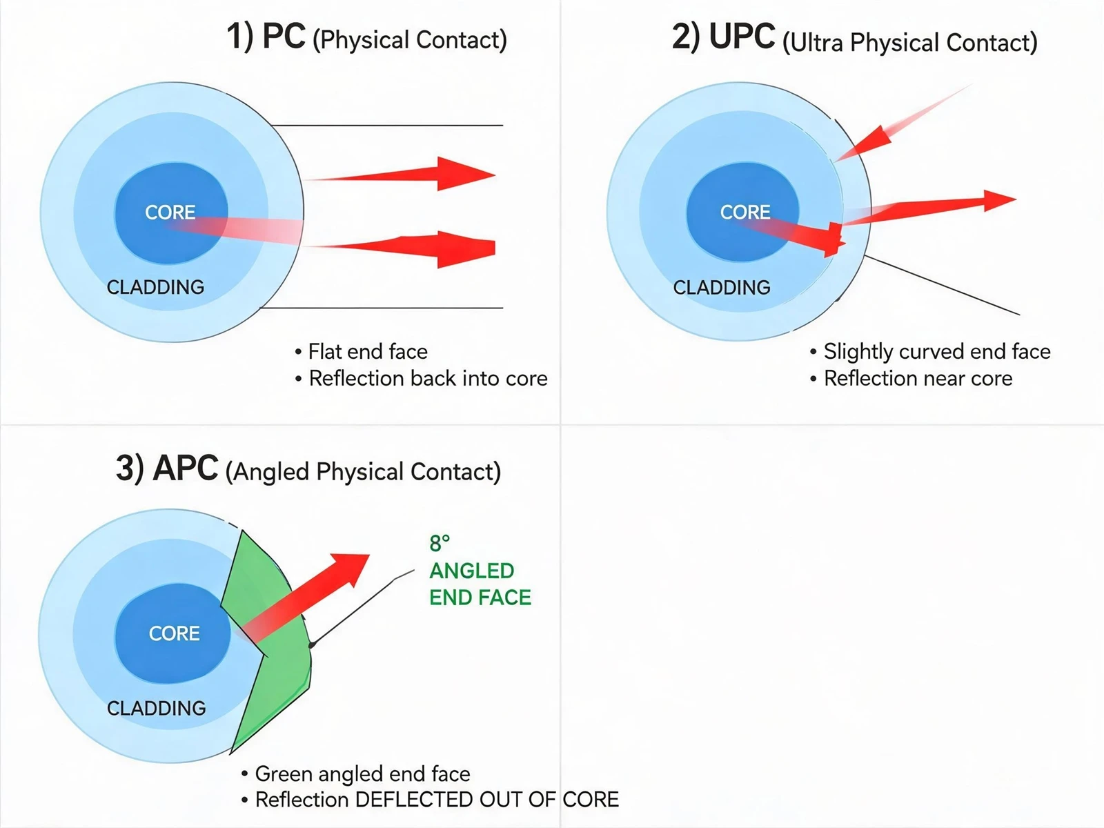
"SC" without APC or UPC is incomplete wherever end-face polish matters. "APC" without a connector family is also incomplete. The polish type determines the return loss: PC (Physical Contact) achieves approximately 40 dB, UPC (Ultra Physical Contact) achieves 50+ dB, and APC (Angled Physical Contact) achieves 60+ dB. The 8-degree angled polish of APC deflects back-reflections out of the fiber core rather than returning them to the source, which is why APC is required for high-power laser applications and recommended for all PON deployments where back-reflection can destabilize transceivers.
The color coding provides a quick visual check: UPC connectors are blue, APC connectors are green. This is not a convention; it is a standard. Mixing blue and green connectors on the same patch panel is a configuration error that will cause physical damage to the ferrules, because the 8-degree APC angle and the flat UPC surface cannot mate without air gap or physical interference.
|
Polish |
Color |
Return Loss |
Typical Application |
|
PC |
Beige/Blue |
40+ dB |
Multimode, legacy |
|
UPC |
Blue |
50+ dB |
Data centers, GPON |
|
APC |
Green |
60+ dB |
CATV, DWDM, PON, RFoG |
Decoding a Real Catalog Name
Consider this hypothetical catalog title that a buyer might encounter: PLC Splitter 1x32 LGX SC/APC, G.657.A1, 2.0 mm, 1.5 m. It looks detailed. But separating it into the six layers reveals what is stated and what is missing.
|
Layer |
Decoded Value |
Evidence State |
|
Technology |
PLC |
Stated |
|
Topology |
1x32 |
Stated |
|
Power distribution |
Not stated |
Unresolved |
|
Package |
LGX (broad family) |
Stated (dimensions unconfirmed) |
|
Fiber & pigtail |
G.657.A1, 2.0 mm, 1.5 m |
Stated (I/O assignment unchecked) |
|
Interface |
SC/APC |
Stated (port assignment unchecked) |
The title locates a product family but is insufficient for delivery approval. Power distribution is completely absent. The buyer must not assume "equal" from the "1x32" topology; some 1x32 PLC splitters are manufactured with slightly unequal distributions for specific cascade architectures. The exact mechanical fit, port-level interface assignment, and input/output pigtail construction all remain open questions that require a model-matched datasheet.
The PON Evolution Factor: Why Technology Choice Is Forward-Looking
The technology layer is not just about today's network. It is about whether the splitter will still work when the network is upgraded. PON standards are evolving, and each generation uses different wavelengths. A splitter that performs perfectly on today's GPON may become a bottleneck when the network upgrades to XGS-PON, TWDM-PON, or 50G-PON.
GPON operates at 1310 nm upstream and 1490/1550 nm downstream. Standard FBT couplers are optimized for these wavelengths and perform well. But XGS-PON uses 1270 nm upstream and 1577 nm downstream. At 1270 nm, an FBT coupler optimized for 1310 nm will exhibit a shifted coupling ratio and potentially higher insertion loss. At 1577 nm, the same coupler optimized for 1550 nm may show similar degradation. PLC splitters, with their flat 1260-1650 nm response, handle all these wavelengths without degradation.
50G-PON adds further complexity with wavelengths in the 1342-1358 nm upstream and 1485-1500 nm and 1550-1560 nm downstream bands, plus a 1900-2000 nm channel for future coexistence. The 1900-2000 nm range extends beyond the 1650 nm upper limit of standard PLC splitters, which means even PLC technology may require specification review for the longest-wavelength channels. This is a forward-looking consideration that belongs in the technology layer, not in the package or connector layer.
Conclusion: Six Layers, One Decision
The fiber optic splitter is a deceptively simple component. It has no active electronics, no software, no configuration. It splits light. But the six independent layers of technology, topology, power distribution, package, fiber and pigtail, and connector interface mean that "what type of splitter do you need?" is not one question but six, and each requires its own evidence to confirm.
The framework presented here is not a recommendation system. It does not tell you which technology to choose, which package to specify, or which connector polish to require. Those decisions depend on your network architecture, deployment environment, and budget. The framework's job is to ensure that when you make those decisions, you make them consciously across all six dimensions, not by default or by assumption from a compressed catalog title.
The most common failure mode in splitter procurement is not choosing the wrong technology. It is choosing the right technology and the wrong package, or the right topology with the wrong fiber grade, or the right connector family with the wrong polish. These are not engineering failures; they are classification failures, and they are entirely preventable by applying the six-layer framework before the purchase order is issued.





