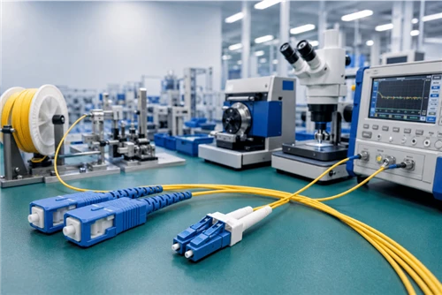
As hyperscale data centers race toward 800G and 1.6T Ethernet, the optical distribution frame (ODF) has transformed from a passive patch panel into a critical bottleneck that determines whether your high-speed transceivers will actually hit their link budgets. The choice between cassette-based and cassette-less architectures is no longer just about port density - it directly impacts signal integrity, maintenance efficiency, and the total cost of ownership over a 15-year facility lifecycle.

The ODF Market at an Inflection Point
The data center ODF market is experiencing the fastest growth among all passive optical product categories. Valued at $2.475 billion in 2025, it is projected to reach $5.145 billion by 2032, growing at a compound annual growth rate (CAGR) of 11.0%. This growth is driven by three converging forces: generative AI workloads demanding unprecedented fiber density, the 400G-to-800G transition tightening link loss budgets, and new regulatory standards such as the EU Data Act interoperability requirements that took effect in September 2025.
Regionally, North America leads with 37.9% of global revenue ($937.4M in 2025), while Asia-Pacific is the fastest-growing region at 34.9% share ($864.1M). By application, cloud data centers account for 54.8% of demand, followed by colocation facilities at 30.4%.
Rack-mount ODFs dominate the market at 64.8% ($1.6B in 2025), reflecting the industry's preference for modular, rack-integrated fiber management over wall-mount or floor-mount alternatives.
The Density Race: From 96 to 864 Fibers per Rack Unit
The push for higher fiber density in 1U of rack space has accelerated dramatically. Five years ago, 72–96 LC duplex ports in 1U was considered high-density. Today, the industry has moved through several tiers of innovation:
|
96 LC fibers / 1U Standard HD |
144+ LC fibers / 1U Ultra-HD |
864 MPO fibers / 1RU Corning EDGE |
Corning's Pretium EDGE platform achieves up to 864 fibers in a single rack unit, while Leviton's eXtreme high-density frames reach 864 ports in 4RU, and Panduit HD Flex enclosures accommodate up to 648 fibers per rack. These numbers are enabled by staggered port alignments, sliding tray mechanisms, and micro-cables that reduce trunk diameters by approximately 30% compared to traditional loose-tube designs.

However, a critical engineering tension underlies this density race. While 288 LC connections can mathematically fit in 1U, field technicians report severe difficulty safely removing a single patch cord from the center of a fully populated matrix without disturbing adjacent ports. This forces network planners to balance theoretical density against practical serviceability - a tension that the cassette versus cassette-less debate directly addresses.
Cassette-Based Architecture: The Modular Workhorse
The cassette-based model remains the dominant architecture in data center fiber management. A cassette is a modular enclosure with factory-terminated fan-out cables: rear ports accept MPO/MTP trunks (12- or 24-fiber), while front ports present LC or SC duplex connectors. This design reduces field-termination errors, accelerates deployment, and enables seamless migration from 10G to 400G/800G without replacing the entire housing.
Advantages of Cassette-Based Systems
• Factory termination quality: Each cassette is pre-terminated and individually tested at the factory, ensuring consistent insertion loss (IL) performance that field termination cannot reliably match.
• Migration flexibility: Swapping a cassette from 10G SR to 400G SR4 or 800G SR8 requires only a module replacement, not a housing overhaul - protecting the structural investment.
• Standardized form factors: Common cassette sizes fit multiple vendor housings, though proprietary designs remain a lock-in risk.
• Simplified troubleshooting: A faulty cassette can be hot-swapped without disrupting adjacent links, minimizing mean-time-to-repair (MTTR).
The ULL Cassette Imperative for 800G
As data centers migrate to 800G, the insertion loss of every component in the optical chain comes under intense scrutiny. A 400G-DR4 link has a total channel loss budget of approximately 3.5 dB. With multiple mated pairs across panel hops, using standard cassettes (~0.75 dB per cassette pair) can quickly consume the entire budget.
Ultra-low-loss (ULL) cassettes specify IL ≤ 0.35 dB per mated pair, cutting the loss contribution nearly in half. The difference between standard and ULL cassettes across a typical four-panel channel can mean 1.6 dB of saved margin - often the difference between a link that passes and one that fails.
Limitations of Cassette-Based Systems
Despite their dominance, cassette-based systems carry inherent trade-offs:
• Proprietary lock-in: Cassette form factors are often vendor-specific, limiting supply-chain flexibility and pricing leverage.
• Additional insertion loss: The MPO-to-LC fan-out within each cassette adds 0.35–0.75 dB per cassette, consuming precious link budget at 800G speeds.
• Physical depth requirements: Cassette housings require more rack depth than direct-adapter panels, which can be problematic in shallow-depth cabinets.
• Density ceiling: Cassette-based panels typically max out at 144–288 fibers per 1U, below the theoretical density of cassette-less designs.
Cassette-Less & Hybrid Architectures: The Emerging Alternative

The cassette-less architecture eliminates the intermediate fan-out layer by connecting MPO/MTP trunks directly to adapter panels at the front of the rack. This approach is gaining traction in native parallel-optic environments where switch ports use QSFP-DD or OSFP form factors that accept MPO directly, without the need for LC conversion.
Pure Adapter Panels
Pass-through adapter panels connect two MPO trunks directly, adding only the adapter mating loss (~0.25–0.35 dB per pair) rather than the full cassette fan-out loss. This is the lowest-loss, highest-density approach for switch-to-switch parallel optic links. The trade-off is reduced flexibility: if an individual fiber fails, the entire trunk must be replaced rather than a single cassette.
Hybrid Flexible: The Go!Foton PEACOC Approach
Launched in March 2026, Go!Foton's PEACOC Any Port Panel (APP) represents a hybrid approach that blurs the cassette/cassette-less distinction. Purpose-built for Base-16 architectures, it supports 8-, 12-, 16-, and 24-fiber formats through six cassette variations that can be mixed and matched within a single panel row.
Key features include:
• Up to 72 adapters and 144 fibers per panel
• Tool-less cassette removal for rapid maintenance
• Support for VSFF connectors (MDC, MMC, SN-MT, CS) for next-generation density
• Up to 9 Base-16 transceivers per RU for 400G/800G/1.6T deployments
The Base-8 and Base-16 design philosophies further optimize fiber utilization. Base-8 uses 100% of fibers for SR4 transceivers (4Tx + 4Rx), compared to the 33% waste inherent in legacy Base-12 designs. Base-16 extends this efficiency to 800G SR8/DR8, using all 16 fibers for 8Tx + 8Rx lanes.
Key insight:
The cassette-less and hybrid approaches are not about eliminating cassettes entirely - they are about eliminating unnecessary fan-out loss where parallel optics connect directly to switch ports, while preserving modular flexibility where LC connectivity is still required. The optimal data center design uses both architectures in different zones of the same facility.
The Density vs Serviceability Dilemma
The engineering tension between theoretical density and practical serviceability is perhaps the most under-discussed aspect of ODF selection. While marketing materials prominently feature "864 fibers per RU" claims, the operational reality is more nuanced.
The Finger Access Problem
In a fully populated 288-fiber 1U panel, the horizontal spacing between adjacent LC duplex connectors can be as little as 8–10mm. A technician wearing anti-static gloves needs approximately 15–20mm of clearance to safely grasp and extract a single connector without applying lateral force to neighboring ports. At full density, this is physically impossible - extracting a center connector inevitably disturbs its neighbors, risking micro-misalignment that introduces intermittent loss.
Front and Rear Cable Management
Robust front cable management is well understood, but rear cable slack management is frequently overlooked. Heavy multi-fiber trunks entering the rear of cassettes without proper strain relief place severe tension on MTP internal connections, causing signal degradation over time.
Best practice requires:
• Integrated waterfall routing guides on both front and rear of the panel
• Physical bend-radius safeguards that enforce manufacturer-specified minimums
• Strain-relief brackets that support trunk cable weight independently of the connector
• Adequate slack storage that accommodates thermal expansion and contraction cycles
Thermal Considerations
Over-densifying active racks restricts airflow. Thousands of patch cords blocking exhaust fans can create localized thermal hotspots that accelerate connector adhesive aging and shift insertion loss over time. As rack power densities rise beyond 30kW per rack in AI training clusters, this becomes a first-order design constraint rather than a secondary concern.
Smart ODF: From Passive Infrastructure to Intelligent Management
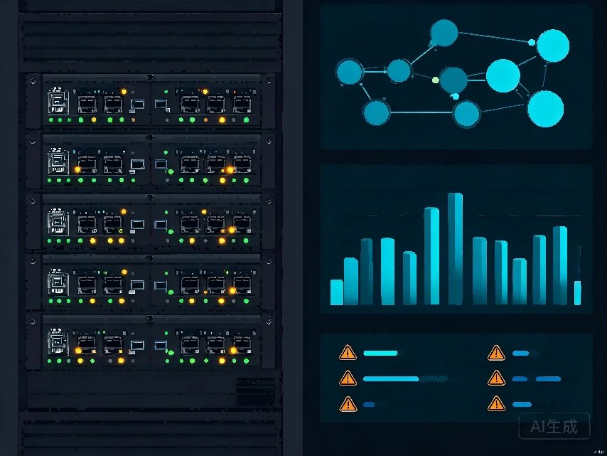
Traditional ODFs are "dumb resources" - physical infrastructure with no visibility into port status, connection integrity, or fiber routing. This makes fault location and inventory management labor-intensive, often requiring technicians to physically trace cables through maze-like installations. The intelligent ODF (iODF) addresses these limitations through electronic tags, sensors, and management software.
Core Smart Capabilities
• Real-time resource management: Automatic port-connection-status identification and accurate fiber-route recording eliminate the manual documentation burden.
• Electronic workflow guidance: LED indicators guide O&M personnel to the correct port, preventing incorrect plugging and unplugging that causes service disruptions.
• Rapid fault localization: When a link is interrupted, the system instantly identifies the physical port location, reducing mean-time-to-repair from hours to minutes.
• Remote link diagnostics: On-demand testing eliminates the need for technicians to physically connect test equipment at various points along the path. Tests that previously took hours now complete in minutes.
Robotic Patch Panels: The Telescent Model
Telescent offers a robotic patch panel system that remotely reconfigures network connections via software, with integrated power monitoring and optional OTDR for on-demand diagnostics. This enables software-defined fiber connections that can be reconfigured within minutes - a capability previously impossible with physical patch panels. The system supports capacity planning through predictive analytics, automatically identifying underutilized links and suggesting reconfigurations to optimize resource allocation.
AI-Driven Predictive Maintenance
The next frontier in smart ODF technology applies machine learning algorithms to multi-dimensional performance data collected from optical modules and cable-monitoring sensors. By analyzing vibration patterns, temperature trends, and loss fluctuations, these systems can predict fiber degradation before it causes service-affecting failures. Huawei's OptiXstar iDF801, updated in October 2024 for 800G data center interconnects, represents this convergence of optical distribution and intelligent management.
Engineering ODF for a 15-Year Lifespan
Data center facilities are typically designed for 15–20 year lifespans, but the optical infrastructure within them is often treated as a consumable. This misalignment leads to premature degradation, unexpected maintenance costs, and degraded signal performance. Three engineering principles are critical for ensuring ODF longevity:
1. Bend Radius Protection
Macro-bending and micro-bending cause light to escape the fiber core, resulting in insertion loss or, in extreme cases, fiber fracture. Even bend-insensitive OM4 and OS2 fibers have minimum bend radius specifications that must be respected inside patch panels. Panels must incorporate physical routing guides and spools that enforce manufacturer-specified minimum bend radii, typically 10× the cable outer diameter for long-term installation and 20× for temporary handling.
A common failure mode occurs when trunk cables entering the rear of cassettes make sharp turns to reach the connector. Even though the panel may have routing guides on the front, the rear path is often left to the installer's discretion, leading to bend-radius violations that are invisible during visual inspection but detectable through OTDR testing.
2. Thermal Stability of Panel Materials
As rack power densities increase, panel material selection becomes a long-term reliability factor. Cold-rolled steel and high-impact polycarbonate are the two most common panel materials. Both must resist warping across the temperature range encountered in a high-density rack over a 10–15 year lifespan. Material warping of even 1–2mm can misalign adapter ports, increasing mating loss and eventually causing intermittent connections.
In AI training clusters where rack power can exceed 30kW, localized temperatures inside fully loaded panels can reach 50–60°C. Panels rated only for standard data center environments (typically 0–45°C) may experience accelerated adhesive softening and structural deformation in these high-thermal zones.
3. Modular Scalability and Standards Compliance
Cassette-based panels allow seamless migration from 10G to 400G/800G without replacing the entire housing - a critical advantage for long-term investment protection. However, this scalability depends on compliance with industry standards:
• TIA-568.3-E: Defines optical fiber cabling components and their performance requirements, ensuring interoperability across vendors.
• ISO/IEC 11801: International standard for customer premises cabling, specifying acceptable insertion loss levels and connector performance grades.
• TIA-942-C: Updated data center infrastructure standard raising Tier-4 fiber expectations, reflecting the demands of AI and high-performance computing workloads.
Slide-Out vs Fixed Trays
The choice between slide-out (drawer-style) and fixed trays has long-term operational implications. Slide-out trays provide better access for dynamic data centers with frequent moves, additions, and changes (MACs), but require adequate slack management to avoid cable strain during sliding operations. Fixed trays offer lower cost and reduced strain risk but make maintenance in densely populated racks more challenging.
Selection Decision Framework
The following decision matrix synthesizes the key factors discussed throughout this article into an actionable framework. It maps common deployment scenarios to the recommended ODF architecture, cassette type, and management approach.
|
Deployment Scenario |
Architecture |
Cassette Grade |
Management |
Target Density |
|
800G AI Training Cluster |
Hybrid (Base-16) |
ULL (≤0.35 dB) |
Smart ODF + AI |
288–864 / RU |
|
400G Hyperscale DC |
Cassette-based |
ULL (≤0.35 dB) |
Smart ODF |
144–288 / RU |
|
100G Enterprise DC |
Cassette-based |
Standard (~0.75 dB) |
Passive + docs |
96–144 / RU |
|
800G Native Parallel |
Cassette-less |
N/A (direct MPO) |
Smart ODF |
288+ / RU |
|
Colocation / Multi-tenant |
Cassette-based |
Standard to ULL |
Smart ODF (billing) |
96–144 / RU |
|
5G / Edge (outdoor) |
Cassette (sealed) |
Standard |
Passive |
48–96 / RU |
The recommended rows highlight the two scenarios where hybrid cassette-less and Base-16 architectures deliver the strongest ROI: 800G AI training clusters that need maximum density with intelligent management, and native parallel-optic switch-to-switch links where eliminating fan-out loss directly enables longer reach at 800G.
Recent Industry Developments (2024–2026)
The ODF landscape has seen significant product launches in the past two years, reflecting the acceleration of AI-driven data center buildouts:
• March 2024: Corning enhanced its Pretium EDGE 2.0 platform specifically for AI-driven data centers, optimizing for higher fiber density and improved cable management.
• September 2024: CommScope launched the SYSTIMAX 360 fiber management platform targeting hyperscale deployments with integrated cable routing and strain relief.
• October 2024: Huawei updated its OptiXstar iDF801 ODF for 800G data center interconnects, incorporating intelligent monitoring capabilities.
• March 2026: Go!Foton launched the PEACOC APP Base-16 optimized fiber patch panel, designed specifically for AI data centers with support for VSFF connectors and mixed cassette configurations.
The rapid cadence of these launches underscores a market in active transition. Vendors are racing to address the specific pain points of 800G migration: tighter loss budgets, higher fiber counts, and the operational complexity of managing massive-scale fiber plants.
Conclusion: Architecture as Strategy
The choice between cassette-based, cassette-less, and hybrid ODF architectures is not a binary technical decision - it is a strategic one that shapes a data center's operational efficiency, migration path, and total cost of ownership for the next decade. The key takeaways for network architects and facility planners are:
• For 800G and beyond, ULL is non-negotiable. Standard-grade cassettes (~0.75 dB) cannot reliably meet 3.5 dB channel loss budgets across multi-panel hops. A consistent ULL strategy (≤0.35 dB) across all connections is essential.
• Cassette-less architectures excel in native parallel-optic zones. Where switches connect switch-to-switch via QSFP-DD/OSFP, eliminating the fan-out layer saves 0.4–0.75 dB per hop and increases density.
• Hybrid approaches offer the best of both worlds. Panels like Go!Foton's PEACOC APP that support mixed cassette configurations enable zone-optimized designs within a single rack.
• Smart ODF is becoming a necessity, not a luxury. At fiber counts exceeding 10,000 per facility, manual documentation and fault localization become unsustainable. Electronic port identification and remote diagnostics deliver measurable ROI within 18–24 months.
• Design for serviceability, not just density. The theoretical maximum of 864 fibers per RU means nothing if technicians cannot safely service the panel. Balance density targets against finger access, cable management, and thermal constraints.
As the data center ODF market grows toward $5.1 billion by 2032, the vendors and operators who master this balance - maximum density with practical serviceability, intelligent management with cost-effective deployment, and forward-compatible architecture with current-generation performance - will define the next era of hyperscale fiber infrastructure.