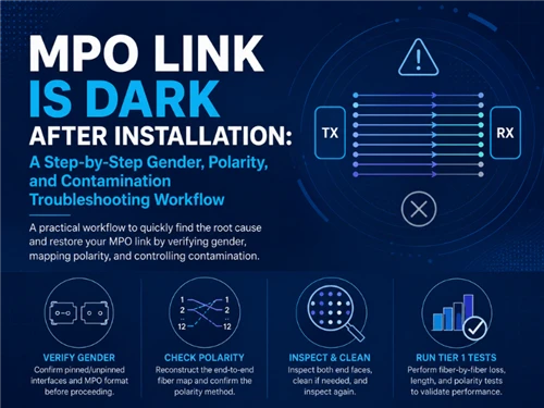
An MPO link that stays dark after installation does not automatically mean the trunk cable is defective. A connector can seat, the adapter can click, and the link can still fail because the pinned/unpinned interfaces do not match, the end-to-end lane map is wrong, or a contaminated ferrule is blocking one or more lanes. The fastest recovery comes from isolating which of those three mechanisms is responsible before any component is replaced.
This workflow keeps the original configuration intact while the fault is found. Reversing jumpers blindly, cleaning every connector on repeat, or swapping the trunk first can destroy the evidence that shows whether the problem is gender, mapping or dirt - and can turn a single mis-mated pair into a multi-site retest.
Why Traditional MPO Troubleshooting Often Fails
The traditional response to a dark MPO link is usually to reverse a jumper, clean every connector or replace the trunk. Each of those actions can fix one specific failure, but none of them proves which failure is present. Worse, they can erase the configuration that made the fault diagnosable.
A VFL only proves that visible light can reach a selected position; it does not certify insertion loss, identify every lane's polarity or confirm transceiver lane assignment. The same problem occurs when engineers treat the trunk label as the channel definition. A structured MPO path can include cassettes, breakouts and equipment cords that each change the lane map, so the printed cable type is only one input to the real channel polarity.
| Traditional action | What it cannot prove | Better diagnostic action |
|---|---|---|
| Replace the trunk immediately | Whether the original fault was gender, mapping or dirt | Preserve the original configuration and document both ends |
| Reverse one jumper | Whether the complete channel follows a defined polarity method | Produce an end-to-end fiber map |
| Use a VFL on one or two fibers | Loss, all-lane polarity or transceiver lane assignment | Run a native MPO Tier 1 test |
| Clean every connector repeatedly | Whether the mark is removable contamination or permanent damage | Inspect–clean–inspect |
| Assume all MPO transceiver ports have the same gender | Compatibility with the actual optical module | Check the module manufacturer's MDI drawing |
1. Verify MPO Gender and Physical Compatibility Before Testing Polarity
MPO gender describes the alignment hardware on the MT ferrule:
- Male or pinned MPO: two guide pins project from the ferrule.
- Female or unpinned MPO: the ferrule has two guide-pin holes.
A normal mated pair requires one pinned interface and one unpinned interface. Two pinned connectors can collide and risk damaging the ferrules; two unpinned connectors can mate mechanically yet fail to align the fibers. Gender is independent of polarity: a female Type B assembly and a male Type B assembly can have the same fiber map, while a female Type A and a female Type B share no lanes.
Do Not Assume Every Transceiver Has the Same Gender
The correct cable gender must come from the optical module datasheet, not a general rule about QSFP, QSFP-DD or OSFP modules. A documented example appears in NVIDIA's Cable Management Guidelines and FAQ: the specified parallel-optics QSFP transceivers expose a defined MDI gender, and that gender - not the module form factor - decides whether the cable end must be pinned or unpinned.
Field Gender Checklist
- Record the manufacturer and complete part number of both optical modules.
- Disable the transmitter and follow the site's laser-safety procedure.
- Inspect the module MDI drawing for pinned or unpinned construction.
- Check the actual cable ends rather than relying only on the carton label.
- Record the rear-interface gender of every cassette or conversion module.
- Confirm that each mated pair contains exactly one pinned side.
- Stop if a connector requires abnormal force.
Also verify the MPO format. MPO-12 and MPO-16 are not interchangeable simply because both are called MPO. Fiber-row geometry, key orientation and active lane count differ, and forcing a 16-fiber connector into a 12-fiber adapter or vice versa will not seat correctly.
| Observation | Most likely interpretation | Next action |
|---|---|---|
| Connector cannot be fully seated | Male-to-male collision, wrong MPO format or wrong keying | Stop; compare ferrules and MDI drawings |
| Connector seats, but every lane is unstable | Female-to-female mating or poor pin alignment is possible | Inspect both interfaces and verify pin configuration |
| Direct equipment cable works, panel channel does not | Cassette rear-interface gender or mapping may differ | Audit every panel-side mating pair |
| Link changes when the connector is touched | Pin damage, incomplete seating, contamination or cable strain | Inspect pins, ferrule and connector retention |
2. Reconstruct End-to-End Polarity Instead of Trusting the Trunk Label
Polarity is a channel-level requirement: every transmitter must arrive at the correct receiver. The cable label describes one assembly, not the complete path through cassettes, breakouts and equipment cords. Reconstructing the channel is what separates a real fix from a lucky reversal.
For a common single-row 12-fiber assembly, the cable-level maps are:
| Assembly type | Simplified mapping | Typical description |
|---|---|---|
| Type A | P1→P1, P2→P2 … P12→P12 | Straight-through |
| Type B | P1→P12, P2→P11 … P12→P1 | Full reverse |
| Type C | P1→P2, P2→P1, P3→P4, P4→P3 … | Pairwise flip |
"Type A/B/C cable" and "Method A/B/C channel" should not be used as if they mean exactly the same thing. ANSI/TIA-568.3-E defines the channel methods; the individual cable type is only one input. An engineer should map the entire path:
Transceiver A MDI → equipment cord → cassette A → trunk → cassette B → equipment cord → transceiver B MDI
For each component, record:
- Connector format and active fiber count
- Key orientation
- Pinned or unpinned interface
- Internal fiber map
- UPC or APC polish
- Near-end and far-end port numbering
Documented Parallel-Optics Mapping Example
In the NVIDIA QSFP example, fiber position 1 at transceiver A must reach position 12 at transceiver B. The remaining active lanes follow the same swap pattern. Designers often use a Type B cable or a Type B cassette to achieve that swap, but the method is defined by the assembled channel, not by a single cable.
However, "use Type B for SR4" is not a universal troubleshooting rule. A cassette, harness or breakout module may already invert the lanes, so the same SR4 transceiver can require a Type A cable in one design and a Type B cable in another. Glory's GL-MP6 modular MPO fiber patch panel, for example, publishes an 8-fiber Type B cassette option with a pinned rear interface, which moves the polarity decision into a documented, replaceable cassette rather than the field-made jumpers.
Read the Failure Pattern Before Changing Components
| Failure pattern | Strong diagnostic clue | Confirmation test |
|---|---|---|
| All lanes are dark, but loss is acceptable | Wrong end-to-end polarity or MDI mapping | Native MPO mapping test |
| Alternating or paired lanes are wrong | Type C component used in an incompatible parallel-optics channel | Compare the measured map with the expected map |
| Link works directly but fails through cassettes | Cassette transition or adapter orientation differs | Test the trunk and each cassette separately |
| Correct fibers carry light but the link does not initialize | Tx may be arriving at Tx rather than Rx | Compare the map with both transceiver MDI diagrams |
| Only one or two lanes have high loss | Contamination, ferrule geometry or local damage is more likely than whole-channel polarity | Inspect and test the affected positions |
A VFL remains useful for a quick continuity check, but a dedicated MPO optical loss test set is the more reliable way to certify the lane map and per-position loss at once.
3. Inspect Contamination, Then Certify Every Active Fiber
After gender and component compatibility have been confirmed, inspect both mating surfaces. Do not inspect a live optical connection, and do not clean as a default first step - unnecessary wiping can scratch a clean ferrule or spread debris.
IEC 61300-3-35:2022 addresses the observation and classification of debris, scratches and defects on connector end faces, and it is the reference most operators use for pass/fail criteria.
Use the following workflow:
- Inspect the cable plug and the mating port.
- If both pass the required inspection criteria, mate them without unnecessary cleaning.
- If loose contamination is present, dry-clean with an MPO-specific cleaner.
- Re-inspect the complete ferrule.
- If oil or film remains, use an approved wet-then-dry process.
- Re-inspect before mating.
- If the same mark remains, treat it as possible scratching, pitting or ferrule damage rather than continuing to clean.
Glory's fiber connector cleaning guide provides the detailed inspect–clean–inspect procedure. The related fiber patch cord and MPO product pages publish insertion-loss and return-loss evidence for the assembled components.
Tier 1 Before Tier 2
For an installed MPO channel, Tier 1 should record:
- Fiber-by-fiber insertion loss
- Channel length
- Polarity or complete lane mapping
- Pass/fail limits tied to the approved design
- Wavelength, reference method and test-cord configuration
TIA's MPO testing summary explains that TIA-526-28 and ANSI/TIA-568.3-E cover MPO-specific Tier 1 requirements. TIA-526-28 defines the reference methods and per-lane loss limits for array connectors, while Tier 2 OTDR is reserved for locating a fault once Tier 1 fails.
Use Tier 2 OTDR testing when Tier 1 fails and the location of the loss event is still unknown. OTDR can help separate a connector event from a cable event and confirm whether the problem is at a panel, a cassette or along the trunk.
Real-World Scale Scenario: 600 MPO Links and 7,200 Fibers
A VIAVI MPO network testing application note documents a commissioning example involving 50 trunks, 600 MPO links and 7,200 fibers. At that scale, manual reversal and VFL tracing cannot certify every lane efficiently; a native MPO workflow records all positions and produces a per-link report.
The engineering lesson is not simply that a dedicated tester is faster. A native MPO workflow preserves the relationship between each lane, its loss and its position, which is exactly the evidence this troubleshooting method depends on when a link goes dark later.
Build a Testable MPO Channel, Not Just a Cable Assembly
The most reliable product solution begins with a channel drawing and acceptance plan. Ordering only "OM4, MPO-12, Type B" leaves the gender, intermediate components and test limits undefined, which is how a dark link appears at commissioning.
A complete MPO RFQ should include:
| Specification field | Required information |
|---|---|
| Application | Ethernet/InfiniBand standard, speed and transceiver part number |
| Interface | MPO-8/12/16/24, UPC/APC and key orientation |
| Gender | Pinned or unpinned at end A and end B |
| Fiber | OS2, OM3, OM4 or OM5; total and active fiber count |
| Polarity | Expected end-to-end lane map, not only cable type |
| Intermediate components | Cassette, adapter, breakout and patch-panel mappings |
| Optical acceptance | Test wavelength, per-lane IL/RL limits and allowed lane spread |
| Inspection | Required IEC 61300-3-35 criteria |
| Documentation | Per-unit or per-batch report, serial/lot traceability and mapping record |
| Labeling | End A/B, polarity, gender, fiber count and destination |
Glory's MTP/MPO cabling portfolio and GL-MP6 modular patch-panel platform can be combined for trunk, cassette and high-density cross-connect builds. The objective is not to sell a Type B cable as a universal cure. It is to deliver a known pinned/unpinned configuration, a documented lane map and a test report that matches the actual channel.
From the Troubleshooting Workflow to the Product Solution
The right products make the three failure modes - wrong gender, wrong polarity, contamination - observable and correctable instead of guessable. Each item below is selected because it removes one of the unknowns this workflow warns about: a defined cassette rear gender, a factory polarity map, a clean LC transition, or a fully tested patch cord.
| Troubleshooting step | Glory product that helps |
|---|---|
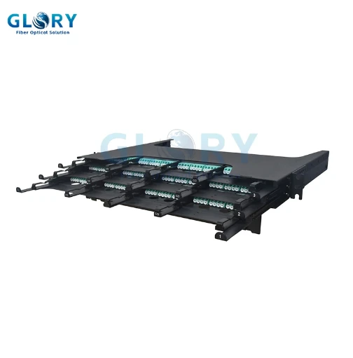
| Verify gender / pinned-unpinned at the panel | GL-MP6 MPO Fiber Patch Panel - cassette rear gender is defined, not field-made |
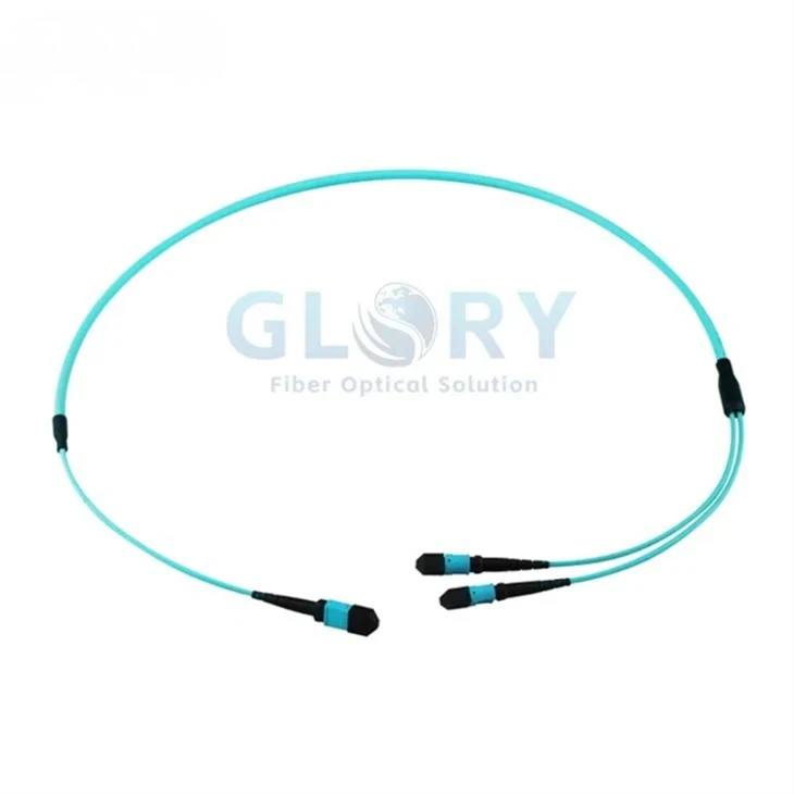
| Establish a known end-to-end polarity | MPO Trunk Cable - factory polarity map with a per-unit test report |
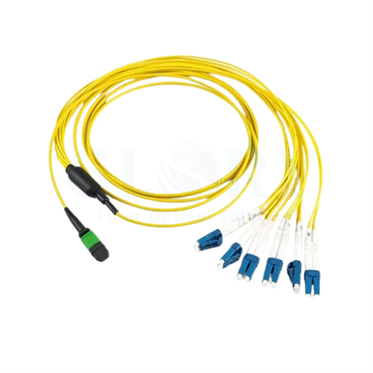
| Transition MPO to LC equipment | MPO to 4×LC Breakout Cable - Type B, MPO APC → LC, IEC/TIA compliant |
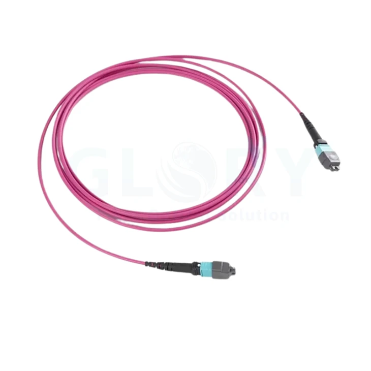
| Cross-connect and run native MPO Tier 1 | MPO Fiber Patch Cord - Elite low-loss, 100% tested, per-cord traceability |
Specify the MPO Channel as One Documented Assembly
Send Glory Optical the transceiver part numbers, required gender at each end, target polarity method, fiber type and count, cassette plan and the test limits you will accept. The engineering team can assemble trunk, cassette and patch cords as one mapped, tested channel before shipment.
Request a Quote View MTP/MPO PortfolioFrequently Asked Questions
Q: Why is my MPO link completely dark immediately after installation?
A: The most common root-cause groups are an incompatible pinned/unpinned interface, wrong end-to-end lane mapping, contamination, or a damaged ferrule or guide pin. A dark link does not automatically mean the trunk cable is defective; preserve the original configuration and document both ends before changing parts.
Q: Can the wrong MPO gender cause a dark link even if the connectors enter the adapter?
A: Yes. Two unpinned connectors can lack the guide pins required for precision fiber alignment, while two pinned connectors can collide and risk damaging the ferrules. A normal mated pair needs exactly one pinned interface and one unpinned interface.
Q: Are MPO transceiver ports always male or always female?
A: No universal assumption should be used for procurement. The correct cable gender must come from the optical module manufacturer's MDI drawing, not a general rule about QSFP, QSFP-DD or OSFP modules.
Q: Is Type B always the correct polarity for SR4 links?
A: No. Type B is common for direct SR4 equipment-to-equipment connections, but cassettes, modules and breakout harnesses can already invert or re-map the lanes. Map the complete channel rather than assuming a cable type.
Q: Should a new MPO cable be cleaned before first use?
A: It should be inspected before first use. Clean it only if the end face fails the required inspection criteria, then re-inspect before mating. Unnecessary cleaning can introduce scratches or debris.
Q: Can a VFL certify MPO polarity?
A: No. A VFL can support continuity and position tracing, but it does not measure insertion loss or automatically certify the complete lane map. Use a native MPO Tier 1 optical loss test set for polarity and loss verification.
Q: What test information should an MPO supplier provide?
A: The report should identify the assembly and lot, test wavelength, reference method, every fiber position, measured insertion loss and return loss, the polarity or lane map, and the acceptance limit applied. Per-unit or per-batch traceability supports commissioning and later troubleshooting.
Standards and Technical References
- ANSI/TIA-568.3-E: Optical Fiber Cabling and Components - array polarity methods and optical-fiber cabling requirements.
- TIA MPO Test Requirements and TIA-526-28 Overview - Tier 1 loss, length and polarity testing; Tier 2 OTDR testing.
- IEC 61754-7-1:2014 - single-row MPO connector-family interface dimensions.
- IEC 61754-7-2:2017 - two-row MPO connector-family interface dimensions.
- IEC 61300-3-35:2022 - visual inspection and classification of connector end-face debris, scratches and defects.
- IEC TR 62627-01:2023 - fiber connector cleaning methods, tools and contamination guidance.
- IEC 61280-4-5:2020 - attenuation, polarity and length measurement for MPO-terminated installed cabling.
- NVIDIA Cable Management Guidelines and FAQ - documented MPO transceiver gender and lane-assignment example.
- VIAVI Testing MPO Networks Application Note - documented 600-link, 7,200-fiber MPO certification scenario.