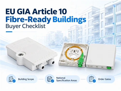
FTTH deployment in an apartment building means extending fiber from the outside network through the building entry, vertical riser, floor distribution points, and horizontal drops to an optical outlet or ONT in each subscribed unit. The difficult part is not merely reaching the property. It is creating an in-building network that can be accessed, installed, tested, maintained, and activated without repeating disruptive construction for every new subscriber.
That distinction is becoming commercially important. The FTTH Council Europe's 2026 Observatory recorded 295 million FTTH/B homes passed and 160 million subscribers across EU39 as of September 2025. Take-up was about 54%, while approximately 85 million homes passed in the EU27+UK remained unsubscribed. The next deployment problem is therefore not coverage alone. It is converting available fiber into service-ready and active homes.
For a complete passive path, Glory Optical's FTTH ODN network solution maps feeder protection, distribution and splitting, access terminals, drop cable, and subscriber outlets as one project BOM. The active OLT and ONT remain operator-selected equipment; their optical class, wavelength plan, and connector interface become inputs to the passive design.
Glory Optical Engineering Team · For network operators, ISPs, EPCs, contractors, distributors, and property-network planners
Quick answer: An apartment building is genuinely FTTH-ready only when the passive path, shared capacity, access rights, labels, and acceptance records allow a subscribed unit to be activated without reopening common construction. Design from the building entry to the apartment outlet as one controlled ODN-not as unrelated drops.
Why MDU FTTH Deployment Is Different From a Single-Home Drop
In a single-dwelling unit, one outside drop normally serves one home. In a multi-dwelling unit (MDU), one building entry must serve many apartments through shared spaces and pathways. Every decision about splitter location, riser capacity, floor boxes, fire requirements, access rights, and labeling affects multiple subscribers.
The network is shared until the final unit
A typical MDU path is:
Outside feeder → building entry point → main distribution point → riser → floor or zone distribution box → apartment drop → wall outlet → ONT
The riser and distribution points are shared infrastructure. A blocked duct, undersized box, inaccessible splitter, or incomplete port map can delay an entire floor rather than one customer. That is why MDU fiber deployment has to be planned as a building system, not a collection of unrelated service orders.
FTTH versus FTTB in an apartment building
The difference is the location where fiber stops:
| Architecture | Fiber endpoint | Final link to the apartment | Operational implication |
|---|---|---|---|
| FTTH | Inside the apartment, at an outlet or ONT | Fiber | Passive optical path reaches the subscriber premises |
| FTTB | Building communications room or basement | Existing copper, coax, or Ethernet | Performance and maintenance still depend on the in-building medium and active handoff |
Germany's regulator uses the same practical distinction. Its Telecoms Annual Report 2025 counted 5.2 million active FTTH connections and about 1.2 million active FTTB connections at the end of 2025; it describes FTTB as fiber ending in the building while copper continues to the apartment.
The real KPI is an activatable unit
Four metrics should not be treated as synonyms:
- Home passed: fiber is close enough for a connection to be offered under the reporting definition.
- Building connected: the building has a physical fiber connection.
- Unit service-ready: the in-building path, capacity, permissions, and records allow the apartment to be connected without new shared construction.
- Home activated: the subscriber has ordered and is using the service.
The third metric is the bridge between network coverage and revenue. It is also where a well-specified passive ODN package can reduce repeat visits.
For the general ODN architecture and loss-budget method behind this path, use Glory's FTTH network design guide. This guide stays focused on the apartment-building decisions that make a unit activatable.
Survey the Building Before Choosing Hardware
The correct box cannot compensate for an unknown route. Start the project with a documented building survey, then release hardware against the approved route and responsibility matrix.
Confirm ownership, access rights, and resident workflow
Record who owns or controls each part of the path:
- outside feeder and building-entry cable;
- building entry room, MDF, or main fiber distribution box;
- common risers, corridors, ceilings, and fire compartments;
- floor distribution points and locked technical spaces;
- the apartment drop, wall outlet, and ONT location;
- future maintenance access and emergency restoration rights.
The operator, building owner or owners' association, installer, property manager, and resident may each control a different step. Agree who approves routes, gives keys, notifies residents, repairs finishes, maintains the passive layer, and owns the as-built records. If multiple service providers may use the building, define non-discriminatory access, spare capacity, port identification, and handover boundaries before installation.
Record the building-entry, riser, and horizontal pathways
The site survey should capture at least:
- number of buildings, floors, units, and mixed commercial premises;
- initial take-up assumption and long-term serviceable-unit target;
- feeder entry location and cable outside diameter;
- available riser shafts, ducts, trays, trunking, and fire stops;
- route length from entry to each floor and from floor node to each unit;
- existing cable occupancy and pull-rope condition;
- bend points, door crossings, protected finishes, and inaccessible ceilings;
- suitable wall space, mounting method, security, moisture, dust, and flood exposure;
- floor-by-floor photos and a numbered route sketch.
Greenfield survey inputs
In a new building, reserve pathways, equipment spaces, bend radius, draw wires, fire stopping, and outlet positions before walls close. The lowest-cost fiber is usually the fiber that can be installed without reopening finished construction.
Brownfield survey inputs
In an occupied building, verify what is actually usable rather than what appears on an old drawing. A nominally empty conduit may be blocked, undersized, or contain undocumented cable. Pilot the most difficult route before finalizing the cable construction or promising an installation rate.
Lock local fire, cable, and documentation requirements
Fire and construction-product requirements are jurisdiction-specific. The RFQ should state the installation environment and the evidence the project requires instead of using "LSZH" as a universal substitute for local compliance.
For EU projects, ask which products are covered by harmonized requirements and request the applicable Declaration of Performance and CE evidence. The European Commission's guidance on Declaration of Performance and CE marking explains that a covered construction product needs a declaration describing its assessed performance. The project designer or local authority must still confirm the required class and installation method.
Once the route is approved, the Glory FTTH cable range can be configured around fiber type, indoor or outdoor construction, reinforcement, jacket material, fiber count, and route method. These fields belong in the approved BOM-not in assumptions made after ordering.
Choose the MDU Distribution Model
Three common models can serve apartment buildings. None is automatically best for every height, take-up curve, or maintenance organization.
Home-run, centralized split, and distributed split compared
| Model | How it works | Strengths | Trade-offs | Best-fit conditions |
|---|---|---|---|---|
| Home-run / point-to-point | A dedicated fiber runs from a central point to each unit | Maximum service flexibility and a simple per-unit path | Highest riser fiber count and pathway demand | Premium or business-heavy buildings; open-access designs requiring dedicated fibers |
| Centralized split | One principal splitter location feeds a fiber to each served unit | Splitter inventory is concentrated; testing and reassignment are easier | More distribution fibers leave the central point; entry-room space and riser count matter | Low- to mid-rise buildings with accessible central space and predictable density |
| Distributed or cascaded split | A first split feeds secondary splitters by floor or zone | Reduces riser fiber demand and supports phased floor activation | More passive locations to document and maintain; every stage must be included in the loss budget | Tall buildings, constrained risers, or phased brownfield projects |
When centralized splitting works
Choose centralized splitting when the building has a secure, maintainable main distribution room, enough riser capacity, and an operational preference for controlling splitters in one location. It can simplify port tracing because technicians do not need to open multiple floor nodes to reach the split point.
When distributed splitting works
Choose distributed splitting when riser space is the binding constraint or when smaller service zones need to be commissioned in phases. Do not select it only because it uses fewer riser fibers. Confirm access to every secondary splitter, restoration procedure, connector count, total split ratio, and engineering margin.
The split location does not remove splitter loss. A cascade can also add connector, splice, and maintenance events. Close the complete installed path against the chosen OLT and ONT class.
Whole-building passive build versus on-demand installation
A useful compromise is to build shared passive infrastructure for the whole building, then activate subscribers in phases. The initial project can install and document the entry point, riser capacity, floor nodes, pathways, and port map while releasing splitters, apartment drops, or ONTs according to the operator's commercial plan.
This does not mean installing unnecessary active equipment. It means avoiding repeated work in shared areas. A second contractor should not need to reopen the same riser because the first phase was sized only for day-one orders.
Glory's ODN solution workflow treats homes passed, initial connections, take-up, growth reserve, split locations, and restoration access as linked design inputs. That is the correct level for comparing centralized and cascaded options.
Map the Passive ODN From Building Entry to the ONT
After selecting the model, divide the building into segments. Each segment has a different mechanical, environmental, and maintenance job.
Building entry and main distribution point
The entry point transitions from the outside route to building infrastructure. Specify:
- feeder cable type, outside diameter, and strength-member fixing;
- wall, rack, pole, or vault mounting;
- indoor, sheltered, wet, dusty, or flood exposure;
- splice capacity, pass-through fibers, splitter space, and adapter interface;
- door clearance, working space, lock, labeling, and grounding needs where applicable;
- cable-entry sealing and fire stopping at the building penetration.
Do not select an IP rating from the product name alone. State the actual environment, mounting orientation, cable entries, and third-party evidence required by the project.
Riser and floor distribution
The vertical cable must fit the shaft, installation method, load, bend radius, fire requirements, and future fiber plan. Floor or zone boxes should be accessible to authorized technicians without obstructing escape routes or exposing fibers to residents.
A floor distribution box may hold splices, adapters, a compact PLC splitter, or a combination of functions. Decide which functions are permitted before selecting a port count. For a low-density indoor floor or corridor node, the GL-B25-8A optical fiber termination box provides an 8-core IP54 enclosure with separated routing, splice storage, and configurable SC or LC adapter arrangements. It is a candidate for dry or sheltered positions, not a default choice for wet or exposed sites.
Corridor drop, wall outlet, and ONT handoff
The horizontal drop crosses the part of the project most visible to residents. Specify route appearance, fixing method, fire behavior, maximum pulling load, connector protection, slack location, outlet position, and responsibility for making good finishes.
The subscriber outlet should protect the final bend and provide a clear handoff to the operator-selected ONT. The GL-FN-3/4 fiber wall socket is an indoor SC/FC option; its adapter, polish, cable type, and port configuration must match the rest of the project interface plan.
Why bend-insensitive G.657 fiber matters indoors
Apartment routes contain more tight corners and small management spaces than most feeder routes. ITU-T G.657 defines bending-loss-insensitive single-mode fiber for access networks and building environments. Category A includes G.657.A1 and A2; the appropriate category, cable construction, bend rules, and compatibility must be confirmed for the installed system. Writing only "single-mode fiber" leaves an important indoor performance requirement unresolved.
Convert the Design Into a Capacity-Safe BOM
A useful MDU BOM is a controlled translation of the survey and architecture. It is not a shopping list assembled from product titles.
Size pathways and ports for the building, not only day-one take-up
Separate three numbers:
- initial active subscribers;
- units that can be connected without changing shared infrastructure;
- long-term building capacity, including an approved reserve.
If a 48-unit building has a 40% initial take-up assumption, about 19 apartments may be activated in phase one. That does not mean the riser, route records, or distribution plan should support only 19 apartments.
As an internal planning heuristic, Glory recommends checking a 20% port reserve. Applying that heuristic to 48 units produces 57.6, rounded to at least 58 planned endpoint positions before mapping them into available module sizes. The final reserve may be higher or lower depending on owner requirements, open-access obligations, commercial premises, spare-fiber policy, and restoration strategy.
Match every segment to the correct cable, enclosure, and splitter
| Segment | Typical passive item | RFQ fields that must be explicit | Relevant Glory page |
|---|---|---|---|
| Building entry | Closure, FDB/FTB, splice and adapter hardware | Cable OD, entries, splice count, pass-through fibers, IP/IK, mounting, lock, splitter plan | FTTH ODN solution |
| Vertical riser | Indoor riser or in-building fiber cable | Fiber count, tensile method, bend performance, local fire classification, length and marking | FTTH cable range |
| Floor or zone | Distribution/termination box | Service ports, spare positions, splice tray, adapters, splitter space, access and labels | Fiber box range |
| Optical split | PLC splitter | 1×N ratio, number of stages, package, wavelength range, fiber, connectors, polish, IL/RL limits | PLC splitter range |
| Apartment drop | G.657 drop cable or preconnectorized assembly | Indoor/outdoor transition, jacket, strength members, length, connector and pull protection | FTTH cable range |
| Subscriber handoff | Wall outlet, adapter, pigtail, patch lead | Port count, connector family and polish, slack and ONT interface | Fiber wall outlet range |
Worked example: 48 units with staged activations
For an eight-floor building with six units per floor, a project team might:
- survey and label all 48 apartment routes;
- reserve pathway and endpoint capacity for all units plus the approved spare policy;
- choose centralized or floor-level splitting only after checking the optical budget and riser constraint;
- install the shared entry and riser infrastructure once;
- release apartment drops or preconnectorized kits by floor as orders arrive;
- keep unused ports capped, identified, and shown on the as-built port map;
- test each newly activated path against the same acceptance plan.
The example is a capacity workflow, not a universal split design. The final splitter ratio and product quantities depend on the OLT class, distances, connector plan, installed losses, and operator policy.
Glory field note: why port underestimation causes re-orders
Glory's published fiber termination box installation guide reports that, across more than 200 MDU FTTH projects in Africa and Southeast Asia from 2021 to 2025, 72% of re-orders were caused by underestimating port count at the design stage. This is Glory's own project dataset, not an industry-wide statistic. Its practical lesson is still useful: approve the unit map, reserve policy, box function, and expansion method before releasing the enclosure schedule.
Close the Optical Budget and Acceptance Plan Together
The design is incomplete until the proposed path and the acceptance method use the same interfaces, limits, and identifiers.
Calculate the installed path, not a catalogue-only path
Include:
- fiber attenuation at the project wavelengths;
- every splitter stage and its specified maximum insertion loss;
- every connector pair and splice;
- other passive devices;
- route-specific engineering margin;
- transmitter and receiver limits for the selected OLT/ONT optical class.
Use maximum approved project values rather than combining unrelated "typical" values from different datasheets. A splitter ratio that works in a short building can fail when added to a long feeder or an extra cascade. Glory's FTTH network design guide contains the full loss-budget and splitter-ratio workflow; link to it rather than duplicating that topic here.
Separate factory evidence from installed-network acceptance
Factory evidence verifies the supplied component before field handling. Installed-network acceptance verifies the route after pulling, splicing, mating, bending, and labeling. A project should define both.
Connector inspection and cleaning
IEC 61300-3-35:2022 provides procedures and criteria for visual inspection of fiber-optic connector end faces. The standard also makes an important distinction: visual inspection does not replace optical performance measurement. Use an inspect-clean-inspect process, then apply the project's loss and return-loss tests.
End-to-end loss, OTDR, labels, and as-built records
At handover, require the agreed combination of:
- continuity and port-map verification;
- end-to-end optical loss results;
- OTDR traces at project-defined wavelengths and settings;
- connector inspection records where required;
- splitter and adapter identification;
- cable length, fiber count, and batch/route labels;
- as-built route, splice, floor, and subscriber records;
- exceptions, repairs, and retest results.
Thresholds and file formats should be agreed before construction. Changing the acceptance rule after installation creates disputes and may make results incomparable across contractors. Glory's FTTH ODN project package can include configured drawings, component test data where specified, labeling, packing schedules, and project-defined test documentation.
Reduce Resident Disruption and Time to Activation
The fastest activation is usually the one that avoids reopening shared infrastructure.
Preconnectorized versus field-spliced drops
Preconnectorized drops can reduce work at floor nodes and inside apartments, but they require accurate length planning, connector protection during pulling, compatible hardened or indoor interfaces, and storage for excess length. Field splicing tolerates more route variation but requires trained labor, clean work areas, splice protection, and on-site testing.
Use preconnectorization when routes are repeatable and measured accurately. Use field splicing when lengths vary, pathways are uncertain, or the operator's restoration model favors spliced joints. Hybrid projects are common: spliced riser distribution with preconnectorized final drops.
Pack, label, and release material by building and floor
One project-wide bulk shipment can transfer sorting work to the site. For larger rollouts, release materials by building, floor, or construction phase. A package can include the correct box, loaded splitter or adapter configuration, labeled pigtails, drops by length, wall outlets, fasteners, and a matching port schedule.
This reduces the risk of an installation appointment arriving before the design, drop, or splitter box. It also makes shortages visible before technicians enter occupied space.
Build the passive layer once and activate subscribers in phases
Where ownership and local rules allow it, complete common pathways, riser capacity, fire stopping, floor-node mounting, and the building port map as one controlled scope. Activate individual apartments as orders are confirmed. The approach separates shared construction from subscriber timing and gives sales teams a reliable definition of "service-ready."
Glory can configure preconnectorized access terminals, drop cable, PLC splitters, and subscriber outlets against the same connector and labeling plan. The benefit comes from interface control, not from calling every product "plug-and-play."
Germany Shows Why In-Building Fiber Is the Next Bottleneck
Germany is a useful case study because outside coverage is rising while in-building conversion remains difficult.
Homes Passed, Connected, and Activated are different metrics
VATM and DIALOG CONSULT's 2026 market analysis forecast 32.0 million homes passed, 12.5 million homes connected, and 7.8 million homes activated by the end of 2026. It forecast a 30.2% take-up rate for competing operators and 17.9% for Deutsche Telekom. These are forecasts, not the Bundesnetzagentur's year-end actuals, but they illustrate why each stage needs a separate KPI.
NE4 and whole-building deployment
Germany commonly describes in-building infrastructure as Network Level 4, or NE4. VATM's multi-family-building position paper reported in 2025 that only 2.9 million of roughly 30.5 million households in two-family and multi-family buildings had fiber connections; for buildings with seven or more units, the figure was only 400,000.
VATM identifies lengthy coordination, unclear responsibilities, limited technical knowledge, and legal uncertainty as delays. It argues that upgrading the whole building can reduce repeated interference, time, and cost. The broader lesson applies beyond Germany: a street build does not create an active customer until the building's rights, pathways, passive capacity, and handover are resolved.
VDE 0800-730 as a German material-planning reference
The February 2026 VDE 0800-730 guideline addresses material requirements for FTTH in-building networks in new and existing multi-dwelling buildings and considers CPR, German fire-route guidance, and state building rules. It is a useful starting reference, not an automatic declaration that a product or route complies. The project's designer, authority, and contractual documents remain decisive.
For a German or other regulated MDU project, submit the required fire classification, documentation language, connector plan, labels, and acceptance format through Glory's ODN project workflow. Do not ask a factory to infer local building approval from a generic product description.
What to Put in an MDU FTTH RFQ
A complete RFQ lets suppliers quote one compatible system instead of several ambiguous products.
Network and demand inputs
- GPON, XGS-PON, or other PON type;
- OLT and ONT optical class, wavelengths, receiver limits, and connector interface;
- number of buildings, floors, residential units, and commercial units;
- homes passed, day-one activations, service-ready target, growth, and spare policy;
- centralized, cascaded, or home-run topology and every split ratio;
- feeder, riser, horizontal, and in-unit distances;
- greenfield or occupied brownfield conditions.
Hardware and interface inputs
- each cable construction, fiber type/count, jacket, fire requirement, and length;
- box function: splice, split, patch, pass-through, or combination;
- port count, loaded adapters, spare positions, and splice capacity;
- indoor/outdoor environment, IP/IK requirement, mounting, lock, and cable OD;
- splitter package, specified maximum IL/RL/PDL, pigtail length, and connector polish;
- wall outlet and ONT handoff;
- preconnectorized or field-spliced drops;
- applicable declarations, certificates, and test reports.
Acceptance, labeling, and delivery inputs
- port, circuit, building, floor, and apartment naming convention;
- factory component-test data required with each batch;
- inspection, end-to-end loss, OTDR, return-loss, and continuity requirements;
- thresholds, wavelengths, launch/receive method, file format, and sample rate;
- as-built drawings, port maps, splice schedules, and exception records;
- packaging by project, building, floor, or phase;
- sample approval, change control, spare kits, and replacement method.
Glory's project-specific ODN quotation workflow can begin with a route sketch, unit table, or partial GIS export. The important step is to expose missing decisions before production rather than after installation.
Glory Product Recommendations by MDU Segment
Product selection should follow the approved function and environment. The examples below are starting points, not universal replacements for a project BOM.
Low-density floor or corridor node
Consider the GL-B25-8A 8-core optical fiber termination box for compact, dry, indoor or sheltered floor/zone locations. Its published configuration integrates cable fixing, splicing, routing, slack storage, and adapter termination in an IP54 PC+ABS housing. Confirm SC or LC adapters, polish, loaded quantity, pigtails, compact splitter compatibility, and local installation requirements.
Higher-capacity building distribution
The GL-FTB24 24-port fiber termination box provides 24 SC adapter positions and a stated 30 mm minimum fiber-management radius. The published page lists two 1×8 or one 1×16 PLC splitter loading options. Confirm the exact enclosure exposure, adapter polish, splice capacity, splitter loss, cable entries, and approved drawing; 24 adapter positions do not automatically mean 24 active PON outputs.
For a wider selection of termination boxes, access terminals, splice closures, and wall outlets, use the Glory fiber box category.
Splitter, drop cable, and subscriber outlet
- The Glory PLC splitter range lists 1×2 through 1×64 equal-split options, a 1260–1650 nm operating range, and G.657.A1/A2 fiber choices. Specify the project maximum values, packaging, connectors, and 100% test-data requirements.
- The FTTH cable range includes indoor and outdoor drop constructions. Select the route-specific fiber, reinforcement, jacket, fire classification, dimensions, and termination method.
- The fiber wall outlet range protects the subscriber handoff. Match its adapter and polish to the distribution network and ONT patch lead.
The most reliable recommendation is therefore a compatible set, not the "best" individual box: approved cable OD and bend performance, the correct splitter package, enough serviceable and spare ports, one connector system, controlled labels, and matching factory/field evidence.
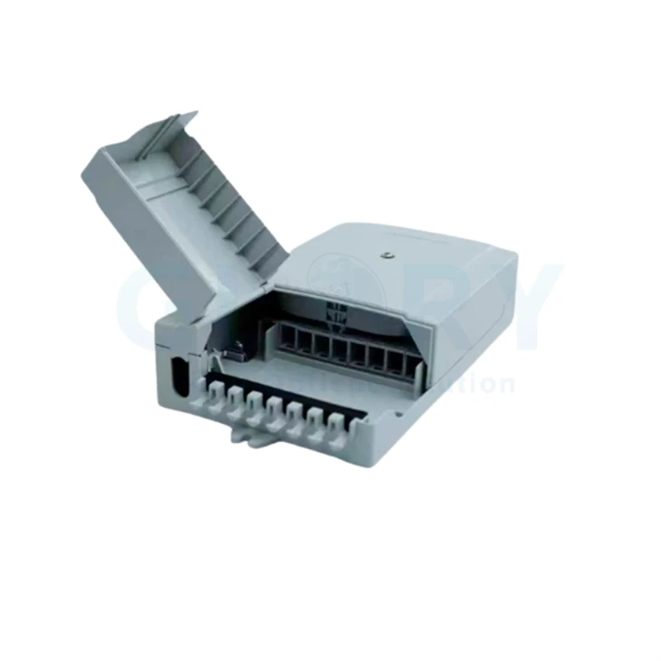
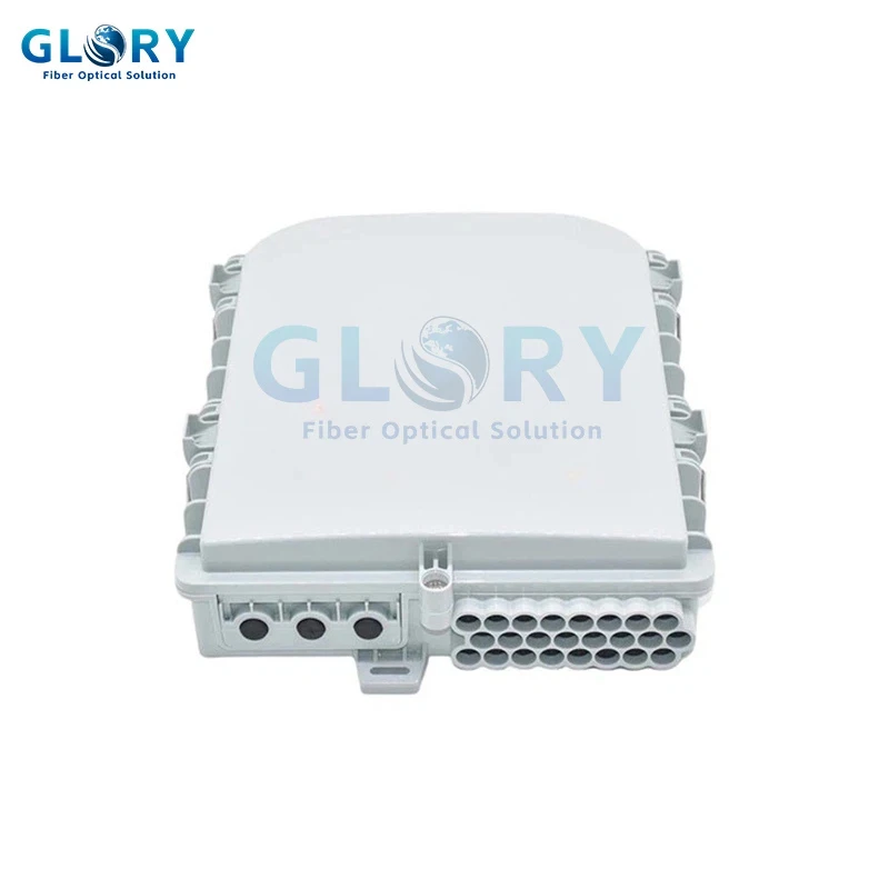

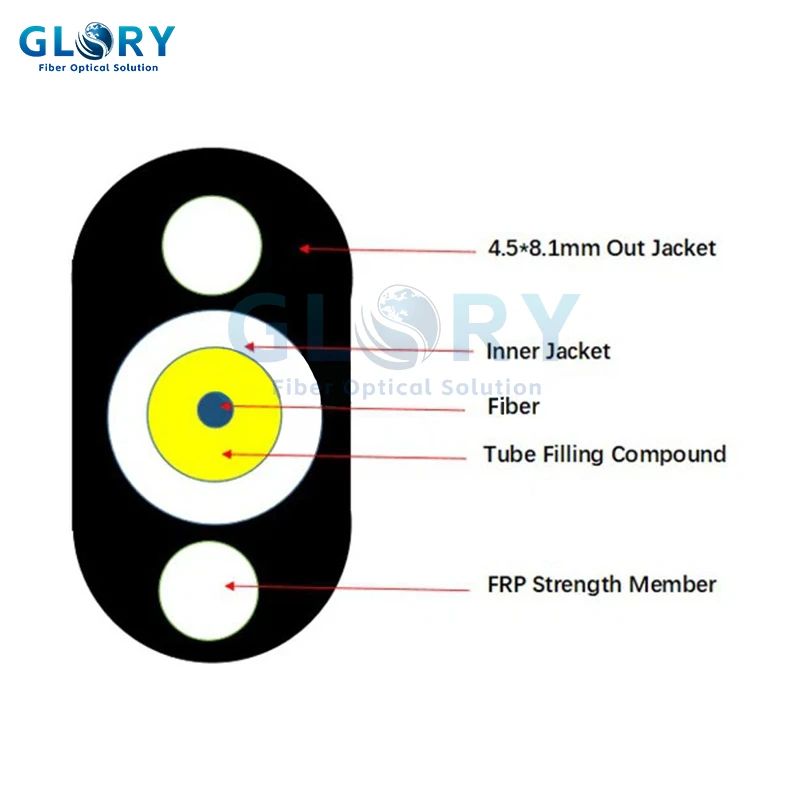

Product images above are the actual images served by the linked Glory product pages. Final selection still requires an approved project drawing, BOM, environment, connector plan, and acceptance criteria.
Frequently Asked Questions
Q: Can an apartment building have true FTTH?
A: Yes. It is true FTTH when fiber continues from the outside network through the building and terminates inside each connected apartment at an optical outlet or ONT. If fiber stops in the basement and copper or coax continues to the apartment, the architecture is FTTB rather than FTTH.
Q: Is FTTH the same as fiber?
A: FTTH is one type of fiber-access architecture. "Fiber" is a broader term that can describe backbone, feeder, building, mobile, data-center, or other optical networks. FTTH specifically brings the optical connection to the home.
Q: What is the difference between FTTH and FTTB in an MDU?
A: FTTH extends fiber into the apartment. FTTB ends fiber at a shared building point and uses another medium for the last segment. FTTB can reduce immediate construction but retains the performance, power, and maintenance constraints of the final in-building medium.
Q: Should an MDU use centralized or distributed splitting?
A: Use centralized splitting when one accessible location can hold the splitters and the riser can support the required distribution fibers. Use distributed splitting when riser capacity or phased floor deployment favors secondary splitters closer to apartments. Verify access, restoration, total splitter ratio, connector events, and optical budget before deciding.
Q: What is a fiber distribution box?
A: A fiber distribution box organizes one or more functions such as cable entry, strain relief, splicing, splitting, adapter termination, drop distribution, slack storage, and labeling. Names including FDB, FTB, FAT, NAP, and OTB vary by market and network position, so an RFQ should describe the required functions instead of relying only on the acronym.
Q: How many spare ports should an MDU reserve?
A: There is no universal percentage. Glory uses a 20% reserve as an internal planning check, but the approved value should reflect the unit count, commercial spaces, open-access model, take-up, restoration policy, module sizes, and future subdivision. Size shared pathways for the long-term building plan even if active equipment is staged.
Q: Can the same passive ODN support GPON and XGS-PON?
A: It can when the fiber, splitters, connectors, wavelength range, reflection performance, and total optical budget meet the selected GPON and XGS-PON system requirements. Do not assume every existing ODN is automatically upgrade-ready; verify it against the actual OLT and ONT classes. Glory's FTTH network design guide shows how to document the shared passive path and its loss margin.
Q: What documents should be included at handover?
A: At minimum, agree the as-built route, port map, splice schedule, cable and component identification, continuity results, end-to-end loss results, OTDR traces, exceptions and repairs, and the factory evidence required for supplied components. The operator should define thresholds and file formats before construction.
Build the Building for Activation, Not Only Coverage
Successful FTTH deployment in an apartment building aligns four things before procurement: access rights, physical pathways, passive architecture, and acceptance evidence. It sizes common infrastructure for the building, then stages subscriber activation without repeating shared construction.
Send Glory Optical the building count, floors and units, initial take-up, PON class, split plan, route lengths, environment, connector system, labeling rules, and test requirements. The team can map those inputs to a project-specific FTTH ODN package covering distribution boxes, PLC splitters, riser and drop cable, subscriber outlets, and the agreed factory documentation.