The short answer
Brownfield MDU FTTH design retrofits fiber into an existing, usually occupied building. Existing conduits, risers, fire barriers, access hours and finishes constrain the route. Greenfield MDU FTTH design coordinates pathways, telecom spaces and unit entries before construction closes them.
The design chain is:
Building condition → verified route → take-rate plan → splitter placement → passive BOM.
A BOM built around an assumed route or a universal take-rate percentage remains a purchasing estimate rather than an engineering result.
1. Brownfield vs Greenfield MDU FTTH: what actually changes?
Brownfield and Greenfield describe the conditions under which a network is designed and installed; they are not cable categories. Those conditions shape labor exposure, pathway control, permitted work, serviceability and the practical transition from feeder fiber to subscriber drops.
| Design variable | Brownfield MDU | Greenfield MDU | Passive-design effect |
|---|---|---|---|
| Building status | Existing and often occupied | New build or major reconstruction | Controls work windows, route access and reinstatement |
| Pathways | Inherited conduit, riser, façade or surface route | Conduit, tray and sleeves can be coordinated | Changes cable count, cable construction and node locations |
| Telecom spaces | May be undersized, shared or absent | Can be reserved and dimensioned | Changes enclosure footprint and splitter centralization |
| Unit entry | Must protect tenants, finishes and access rules | Can be roughed in before handover | Changes drop length, connector method and activation time |
| Demand | Existing services can suppress or delay migration | FTTH may be included at handover | Changes day-one material quantity, not necessarily full route capacity |
| Primary risk | Route uncertainty and labor variance | Coordination changes and late design freeze | Changes where contingency belongs in the BOM |
The Fiber Optic Association's FTTH-in-MDUs reference draws the same practical connection between building design, component placement and service access. Glory's FTTH network design guide provides the next step: translating those building constraints into an ODN architecture and loss budget.
2. Prove the cable route before selecting the splitter
A line on a drawing becomes a usable route only after each space has been verified: property entry, building entry point, riser, floor or zone distribution, corridor transition, unit penetration, and the optical outlet or ONT position. Each transition needs a defined owner, access method, fire-sealing requirement and measurable installation limit.
Brownfield route validation
Brownfield validation should combine a physical walk-through with representative route trials. One successful draw-rope pass through an empty conduit cannot qualify the whole building. Trials should cover the worst credible paths: the longest unit, the highest bend count, an already populated conduit and the route with the most difficult access.
| Field to record | Why it matters | Release criterion |
|---|---|---|
| Usable inside diameter and fill state | Determines whether a cable, microduct or pre-connectorized head can pass | Measured or visually verified rather than inferred from nominal size |
| Route length and bend count | Drives push/pull feasibility and service-loop quantity | Worst representative path trialed |
| Entry and exit access | Controls tool position, pulling direction and tenant time | Installer can work safely at both ends |
| Test article and method | A bare cable, connectorized drop and microduct have different envelopes | Trial configuration matches the intended BOM |
| Installation time | Turns route design into a labor model | Median and worst-case time recorded alongside the fastest pass |
| Before/after optical result | Detects installation damage that visual success can hide | Within the project's approved test limit |
| Failed route and fallback | Prevents improvised façade or corridor work | Fallback route approved by the property and code authority |
What a published Brownfield field case tells us
A published PPC/Belden field case documented a retrofit across ten high-rise blocks, each containing 180 dwellings. The existing 20 mm PVC conduits were already populated, sample routes measured approximately 12–20 m with at least two 90-degree bends, and cable-blowing equipment was not permitted. The previous rodding method required 15–20 minutes before splicing and testing, with total work sometimes exceeding one hour per dwelling. During the reported trial, a 3 mm pushable cable passed in under 60 seconds. Eight apartments were cabled in two hours instead of eight, and the source reported a final OTDR result of 0.05 dB insertion loss.
Interpretation: the results reflect a specific cable, route and crew in a vendor-published case. The transferable lesson lies in the method: reproduce the route geometry, test the intended cable system, and record both installation time and optical performance before freezing the BOM.
Greenfield route coordination
Greenfield projects move route decisions earlier in the construction program. Before ceilings and walls close, reserve a continuous pathway, accessible sleeves, bend-compatible turns, a serviceable building entry point and defined unit entries. The fiber route must also be coordinated with fire stopping, electrical separation, elevator and life-safety spaces, and ownership of shared risers.
Bend-insensitive fiber can improve route tolerance inside apartments and at tight corridor transitions. Select the fiber category against the current ITU-T G.657 recommendation, then check the minimum bend radius and installation load of the finished cable because fiber category alone does not define cable handling limits. Glory's G.657.A1 versus G.657.A2 guide and fiber-optic cable selection principles provide additional input for the cable schedule.
3. Use take rate to stage materials-not to underbuild the route
Take rate is the share of passed premises expected to become active subscribers within a defined period. A useful figure therefore includes a time horizon-launch, 12 months, three years or the design horizon. National averages can provide context, but building-level demand still requires its own forecast.
The Fiber Broadband Association's 2025 North American market update reported average take rates in roughly the mid-40% range based on unique passings. Results at a single MDU may be far lower or higher, influenced by exclusivity, existing contracts, rent structure, demographics, service pricing and whether fiber is installed before occupancy. Existing buildings benefit from a resident survey and a conversion timeline, while new developments need a clear decision on whether every unit will be equipped at handover.
A three-capacity model
A single percentage cannot govern every line of the BOM. Capacity is better assigned across three layers:
| Capacity layer | Recommended planning basis | Typical passive items | Why |
|---|---|---|---|
| Physical route | Full building, plus approved pathway contingency | Riser pathway, sleeves, tray, fire stopping, entry space | Opening finished construction twice is usually the expensive failure |
| Expansion footprint | Design-horizon demand, with a documented route to full building | Enclosure size, mounting space, splice-tray capacity, reserved splitter slots | Protects serviceability without loading every passive module on day one |
| Subscriber-variable material | Day-one active units plus an operational spare policy | Drop cable, wall outlet, pigtail, connectorized assembly, labels | Avoids tying up capital in unactivated apartments |
Take rate controls commercial staging; it does not change the required optical margin, strand identification or route documentation. Comparisons between 1×16 and 1×32 modules should combine the actual OLT/ONT class and connector plan with Glory's 1×16 versus 1×32 PLC splitter guide.
4. Let the route and loss budget choose the passive architecture
MDU FTTH commonly uses centralized, floor-distributed or cascaded splitting. Building type alone cannot select the architecture. The route establishes how many fibers can move through the building in practice, while the optical budget and maintenance model determine how far splitting can be distributed.
| Architecture | Route effect | Operational advantage | Design penalty | Typical fit |
|---|---|---|---|---|
| Centralized single-stage split | Higher distribution-fiber count from the splitter location | Fewer splitter sites; straightforward testing and reassignment | Larger riser cable and termination field | Greenfield with reserved pathways; Brownfield with generous riser capacity |
| Floor or zone split | Lower feeder/riser fiber count; more local drops | Short subscriber drops and modular floor activation | More service locations and enclosure access | High-rise or horizontally wide buildings |
| Cascaded split | Few riser fibers feed several local splitters | Can fit constrained Brownfield routes | More splitter loss, interfaces and fault-isolation complexity | Route-constrained projects after loss-budget approval |
| Home-run fiber with provider cross-connect | Highest fiber count to the building entry | Flexible multi-operator handoff | Space and cable-count intensive | Projects where provider choice is a primary requirement |
Calculate the worst-case optical path
Base the loss budget on the longest, highest-loss service path rather than the average apartment. Add the maximum declared loss for every splitter stage, connector pair, splice and cable segment, followed by the project's engineering margin. Where procurement or acceptance uses maximum values, a typical splitter value cannot serve as the design input.
Glory's GPON loss-budget planning guide shows how split ratio and passive losses interact. The ODN fiber-optic solution overview can then be used to map feeder, distribution and drop components into one passive chain.
5. Build the passive BOM in layers
A reliable MDU passive BOM quantifies the route drawing, port map and optical architecture. Separating fixed building infrastructure from activation-dependent material shows procurement which items are installed once and which can be released at defined take-rate milestones.
Layer A: route and cable support
- Building-entry, riser, distribution and subscriber drop cable by construction, fiber count and measured length.
- Microduct, conduit accessories, tray, fixings, pull cord and approved fire-stopping system.
- Service loops assigned to named locations rather than absorbed into a blanket slack percentage.
- Route, cable and unit labels tied to the as-built port map.
Layer B: passive nodes and optical interfaces
- Building entry enclosure or distribution frame, floor/zone boxes and subscriber outlets.
- PLC splitters by input/output ratio, package, connector type and maximum insertion-loss specification.
- Splice trays, protectors, adapters, pigtails, patch cords, connectorized stubs and dust caps.
- Cable glands, seals and strain-relief parts matched to actual cable diameters.
Layer C: activation kits and controlled spares
- One complete drop-to-outlet kit per day-one activation, managed as a kit rather than as disconnected line items.
- Project-approved spares by failure mode: long lead-time module, field-damage cable, connector and adapter.
- Expansion modules released when take-rate thresholds are reached, while reserved slots stay protected and documented.
Product recommendations by design condition
8-unit floor or zone
GL-FTB-8F 8-core termination box
With 8 listed SC simplex ports, a modular-splitter arrangement and a 168 × 133 × 55 mm PC/ABS housing, this box fits compact indoor floor or riser nodes. The approved project drawing should define the adapter, splitter and mounting configuration.
16-unit zone
GL-FTB-16H 16-port termination box
This listed 16-port IP65 PC+ABS box combines feeder fixation, splicing, storage and space for a micro 1×16 PLC splitter. Its environmental suitability depends on both the ordered configuration and the way the box is installed at the site.
Passive split
1×8 PLC splitter
This splitter can serve an eight-unit floor node or form the second stage of a cascaded design. The order specification needs to fix the package, fiber type, tail length, connector polish and the boundary of the guaranteed loss, including whether connectors are covered.
Subscriber drop
GJXFH/GJXH indoor drop cable
For the final indoor route, selection depends on the required fiber category, jacket and fire declaration, tensile load, bend radius, and the unit-entry method accepted in the destination market.
Apartment handoff
GL-FN-3 / GL-FN-4 fiber wall socket
The 86 × 86 × 25 mm wall-mount family provides a compact handoff inside the unit. Variant selection should follow the drop geometry, cable entry and SC/FC interface rather than faceplate appearance.
Labor control
Pre-terminated cable assemblies
Pre-terminated assemblies can reduce field termination when route trials show that the connectorized pulling envelope will pass and repeatable lengths can be controlled. Where Brownfield conduits remain uncertain, the trial must include the complete connector head and its pulling protection.
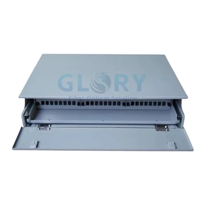
Glory's fiber-optic termination-box selection guide compares enclosures by port count, environment and internal function. Final selection also depends on cable entry, bend management, fire environment, mounting access and the approved loaded configuration; port count, IP rating and splitter capacity cover only part of the project specification.
6. Worked planning model: the same 48-unit MDU, two different BOMs
The following planning model illustrates the calculation method without presenting itself as a construction drawing or field result. It assumes an eight-floor building with six apartments per floor, a 35% launch take rate, a 70% design-horizon take rate and two uninstalled subscriber activation kits held as operational spares.
Both designs preserve a route to all 48 apartments. Take rate stages the drop kits and splitter loading, while the riser pathway continues to support the full building rather than only the 17 launch activations.
| Passive item | Brownfield route-constrained candidate | Greenfield pathway-rich candidate | Design reasoning |
|---|---|---|---|
| Verified route | Existing riser plus eight short floor routes, released only after representative trials | Reserved riser/tray, sleeves and four accessible two-floor zone positions | Same 48-unit coverage; different node density |
| Building entry split | 2 × 1:4 first-stage PLC splitters | 2 × 1:16 modules at launch; one reserved 1×16 slot/module added before demand exceeds 32 | Brownfield candidate feeds eight floor branches; Greenfield centralizes lower-ratio single-stage split |
| Floor/zone split | 8 × 1:8 second-stage modules, one per floor | No second-stage splitter | Brownfield uses a logical 1:32 path per PON branch; Greenfield trades more distribution fiber for fewer split stages |
| Floor/zone boxes | 8 × 8-port boxes | 4 × 16-port boxes | Six units fit an eight-port floor node; planned pathways allow two-floor Greenfield zones |
| Riser distribution | At least 8 working branch fibers plus project-approved spares | 48 subscriber fibers plus project-approved spare strategy | Cascading saves riser fibers; centralization consumes them |
| Day-one drop/outlet kits | 19 procured; 17 assigned and 2 controlled spares | 19 procured; 17 assigned and 2 controlled spares | Activation-dependent quantity follows the same take-rate assumption |
| Expansion footprint | All eight floor nodes and full branch route protected | Three 1×16 module positions and 48-fiber distribution termination protected | Space and route are cheaper to reserve than reconstruct |
| Mandatory release check | Worst-case 1:4 + 1:8 path, connectors, splices, cable and margin pass the optical budget | Worst-case 1:16 path and longest distribution run pass the optical budget | Port arithmetic never overrides the loss budget |
What the model reveals
- The Brownfield candidate uses more boxes and splitter modules but far fewer riser fibers.
- The Greenfield candidate uses a larger distribution fiber count but one splitter stage and half as many zone boxes.
- The same launch take rate produces the same 19 activation kits, yet it does not produce the same fixed BOM.
- The 70% horizon rate reaches 34 units. In the Greenfield candidate, that crosses the 32 outputs available from two 1×16 modules, so the third module must be added before subscriber 33.
- If the Brownfield cascaded path fails the optical budget, the remaining choices involve more fiber, more space or additional PON ports; the loss margin cannot absorb the shortfall.
These assumptions should remain visible as line-item notes in the supplier quotation. Glory can review a marked route, port map and loss budget against available fiber boxes, PLC splitters, FTTH cables and loaded assembly options. A proposed substitution requires a fresh check of the drawing, cable-entry range, connector map and maximum optical-loss values.
7. Put standards, certification and QA evidence into the specification
Terms such as "indoor cable," "LSZH" and "IP-rated box" describe individual attributes rather than a complete compliance package. The applicable requirement depends on the country, building code, installation space and authority having jurisdiction. Required evidence should therefore be written into the RFQ before sample or production approval.
| Requirement | Authoritative reference | What to request in the project file |
|---|---|---|
| Bend-insensitive single-mode fiber | ITU-T G.657 (08/2024), in force | Declared fiber category and cable datasheet; finished-cable bend and load limits |
| EU construction-cable reaction to fire | European Commission CPR guidance and the Official Journal reference to EN 50575 | Required national class, applicable Declaration of Performance, CE information and traceable cable identity |
| FTTx installer competence | FOA FTTx certification requirements | Named competency requirement such as FOA CFOS/H or a project-approved equivalent, plus any local license |
| Passive acceptance evidence | Project optical budget and approved test plan | End-face inspection, continuity/port-map verification, end-to-end loss results and OTDR traces where specified |
Before deployment, translate the acceptance plan into a sequence of installer actions. Glory's FTTH cable installation guide can support method-statement preparation, with the released drawing, manufacturer limits and local code retaining precedence.
8. Common MDU design failures-and how to prevent them
| Failure | Why it happens | Prevention |
|---|---|---|
| The drawing shows a route that the cable cannot pass | Nominal conduit size is treated as a substitute for a route trial | Trial the complete intended cable or connectorized assembly on the worst representative paths |
| The BOM assumes 100% activations on day one | Full-building capacity is treated as immediate material consumption | Separate route capacity, expansion footprint and subscriber-variable material |
| The network cannot serve future demand | Launch take rate is treated as permanent | Define horizon rate, expansion trigger, reserved slots and a documented path to all units |
| A cascaded design fails at the longest unit | Splitter count is selected before the loss calculation | Budget the worst path with maximum declared component losses and engineering margin |
| Boxes are inaccessible or repeatedly disturbed | Port density is optimized without accounting for maintenance access | Approve mounting height, door swing, work clearance and landlord access during the walk-through |
| Pre-terminated drops save no labor | Connector heads cannot pass, or assembly lengths are uncontrolled | Mock up the pulling envelope and freeze the length schedule before production |
| "LSZH" is accepted as full fire compliance | Material wording is mistaken for a regulated classification | Specify the exact local class and documentary evidence |
| As-built records do not match the boxes | Labels, port map and test files use different identifiers | Use one unit-to-port naming convention from factory loading through acceptance |
Each of these failures has a procurement consequence as well as a design cause. The Glory plug-and-play FTTH guide explains where pre-connectorization can reduce field operations once the route, interface and length controls have been proven.
9. MDU FTTH RFQ checklist: information that prevents a generic quotation
The passive-component supplier should receive the following project package. Unknown items should remain visible as open design decisions so that assumptions do not enter the quotation without a record.
- Building profile: Brownfield or Greenfield, floor count, unit count, occupancy status and provider model.
- Route evidence: marked plans, photos, measured lengths, conduit inside diameter/fill, bend count, fire barriers and representative route-trial record.
- Demand plan: launch take rate, horizon take rate, forecast dates, floor distribution and activation-spare policy.
- Architecture: PON technology/class, centralized or cascaded split, splitter ratios, PON-port allocation and multi-operator requirements.
- Optical budget: maximum component losses, connector/splice quantities, cable attenuation and engineering margin.
- Enclosure schedule: location, indoor/outdoor condition, port count, splice capacity, splitter package, mounting, cable entries and environmental rating.
- Cable schedule: fiber category/count, construction, jacket/fire requirement, lengths, service loops, pulling method and drum/coil plan.
- Interface map: connector type and polish, adapter arrangement, pigtail/tail length, labeling and unit-to-port map.
- Evidence: datasheets, drawings, applicable declarations/certificates, sample approval, factory test expectations and site acceptance deliverables.
- Commercial staging: fixed-build quantity, launch activation quantity, expansion lots, packaging by floor/zone and substitution-control process.
Turn the route and take-rate plan into a quote-ready passive BOM
Send Glory the marked building route, unit count, take-rate stages, splitter plan, optical budget and required compliance evidence. The technical-sales team can then map the approved design to boxes, PLC splitters, cables, outlets and pre-terminated assemblies while keeping project assumptions visible in the quotation.
Request an MDU FTTH quotationReview Glory FTTH/ODN solutionsContact technical sales
Frequently asked questions
Q: What is the main difference between Brownfield and Greenfield MDU FTTH design?
A: Brownfield design adapts to existing, often constrained pathways and occupied spaces. Greenfield design can reserve pathways, sleeves and telecom spaces before finishes are installed. The condition changes the route, which then changes splitter placement and the passive BOM.
Q: Should an MDU passive network be built for 100% take rate?
A: The physical pathway and enclosure footprint should normally protect the full-building route, but subscriber-variable items such as drops, outlets and some splitter modules can be staged against documented launch and design-horizon take rates. The final spare and capacity rule is project-specific.
Q: Where should PON splitters be placed in an MDU?
A: Place splitters only after checking verified cable routes, maintenance access, provider policy and the optical loss budget. Centralized splitting uses more distribution fiber but fewer splitter locations; floor-distributed or cascaded splitting reduces riser fiber count but adds service nodes and passive loss.
Q: Is LSZH cable automatically CPR compliant?
A: No. LSZH describes smoke and halogen behavior, while CPR reaction-to-fire performance is declared through an applicable classification and documentation. For EU projects, specify the required class and request the applicable Declaration of Performance and CE information.
Q: What should be sent for an MDU FTTH quotation?
A: Send unit and floor count, marked route drawings, pathway survey or route-trial results, launch and horizon take rates, splitter topology and loss budget, local fire/building requirements, connector interfaces, cable lengths, enclosure locations, port map, spare policy and test-document requirements.
Sources and methodology
This guide combines primary standards and industry references with a transparent engineering planning model. Market take-rate data provide context, while the 48-unit quantities remain illustrative calculations based on the assumptions stated above.
- Fiber Optic Association: FTTH in Multiple Dwelling Units
- ITU-T Recommendation G.657 (08/2024)
- European Commission: Construction Products Regulation guidance
- EUR-Lex Official Journal reference to EN 50575
- Fiber Broadband Association: 2025 North American FTTH Deployment and Market Update
- PPC/Belden: published MDU retrofit field case
- Telenco: current MDU distribution overview from building entry to subscriber outlet