Why FTTH Loss Budget Fails Between Design and Handoff
The office spreadsheet shows 4 dB of headroom. The truck arrives, the ONT is connected, and the receive level is 5 dB lower than planned. Nothing in the formula changed - the design was correct. What changed is everything the formula assumed: a clean connector that was not clean, a route that was longer than the GIS strand record, a feeder fiber that was patched to the wrong splitter during a previous job, or a light-level record that nobody actually wrote down.
Most loss budget articles stop at the equation. In a real FTTH deployment, the equation is the easy part. The hard part is the workflow that connects design assumptions, splitter architecture, connector cleanliness, field margin, test records and handoff documentation - and proves what actually happened on site. This guide covers both: the GPON loss budget math, and the field practice that keeps the math honest.
The spreadsheet tells you what should happen. Field inspection, light-level records and documentation prove what actually happened. A loss budget that ignores either half is a budget that drifts at handoff.

How to Calculate a Basic FTTH GPON Loss Budget
A GPON loss budget is the total allowed optical loss between the OLT and the ONT. Every passive element along the optical distribution network (ODN) consumes part of it. The core relationship is simple:
Total Link Loss = Fiber Loss + Splitter Loss + Connector Loss + Splice Loss + Engineering Margin
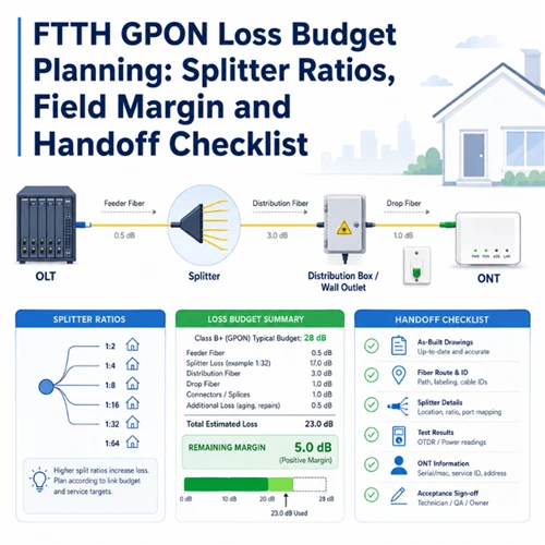
The planned total must stay inside the optical path loss class of your equipment. Under ITU-T G.984.2, GPON defines several classes; Class B+ (13–28 dB) is the de facto deployment standard and is typically dimensioned for a 1:32 split at around 20 km, while Class C+ (17–32 dB) extends reach or split ratio. The newer XGS-PON budget under ITU-T G.9807.1 sits a little higher (around 29 dB for the common N1 class) with tighter return-loss expectations, which matters if you plan to overlay or migrate to 10G PON on the same ODN. Here is each variable, with planning values you can start from.
| Loss element | Planning value (placeholder) | What it depends on |
|---|---|---|
| Fiber attenuation | ~0.35 dB/km at 1310 nm; ~0.21–0.25 dB/km at 1490/1550 nm | Route length and wavelength. The upstream 1310 nm path is usually the worst case. Values per ITU-T G.652. |
| Splitter insertion loss | 1:8 ≈ 10.5 dB · 1:16 ≈ 13.5 dB · 1:32 ≈ 17.0–17.5 dB · 1:64 ≈ 21 dB | Split ratio and excess loss. Usually the largest single passive loss; confirm against the PLC splitter datasheet. |
| Connector-pair loss | ~0.3 dB per mated pair (range ~0.2–0.5 dB) | Number of connector pairs, grade and polish. Frequently underestimated in the field. |
| Fusion splice loss | ~0.1 dB per splice | Splice count across feeder, distribution and drop sections. |
| Engineering / field margin | ~2–3 dB reserved | Aging, repair splices, contamination risk and measurement uncertainty. |
Splitter loss is the value most often quoted as a single "universal" number and most often wrong. A 1:32 split has a theoretical loss near 15 dB before excess loss, so a quoted 1:32 value much below ~17 dB is usually a 1:8 figure repeated by mistake. Always pull the insertion loss from the selected PLC splitter datasheet rather than from memory, and prefer PLC over FBT for ratios at 1:8 and above for uniformity and stability - see PLC vs FBT splitter selection.
A Worked GPON Loss Budget Example
Numbers make the workflow concrete. The example below is a downstream Class B+ planning case for a single-stage 1:32 ODN, with every figure marked as a placeholder to be confirmed against the project datasheets.
| Item | Planning input | Loss contribution |
|---|---|---|
| Fiber length | 6.0 km total at 0.35 dB/km (1310 nm worst case) | 2.1 dB |
| 1:32 PLC splitter | 17.1 dB insertion loss (datasheet placeholder) | 17.1 dB |
| Connector pairs | 6 mated pairs × 0.3 dB | 1.8 dB |
| Fusion splices | 4 splices × 0.1 dB | 0.4 dB |
| Passive subtotal | - | 21.4 dB |
| Engineering / field margin | Reserved | 3.0 dB |
| Planned link total | vs Class B+ limit 28 dB | 24.4 dB (≈3.6 dB headroom) |
The six connector pairs in this example are not a rounding detail - at 0.3 dB each they consume more budget than the entire fiber run. That is the recurring lesson: count every mated pair from the OLT port through the ODF, feeder connection, splice closure, splitter input and output, FDB/NAP and wall outlet to the ONT. A budget that models splitter loss precisely but forgets two connector pairs is already off by more than half a decibel before anyone touches the field.
What Should Be Included in an FTTH Loss Budget Spreadsheet?
A useful spreadsheet does more than print a total. It shows each component's contribution so a technician can see where the loss sits, and it leaves columns for what was actually measured. These are the fields that earn their place.
| Field | Why it matters |
|---|---|
| OLT transmit power | Starting optical power assumption for the link. |
| ONT receive sensitivity | Sets the minimum acceptable receive level for the chosen ONU. |
| Fiber distance | Drives the attenuation calculation; pull from documented strand length, not a guess. |
| Wavelength | Loss differs by wavelength; design to the worst-case direction. |
| Split ratio | The main passive loss contributor and the first thing reviewers check. |
| Splitter insertion loss | Must match the selected PLC splitter datasheet, not a generic figure. |
| Connector pairs | Counted per mated pair across the whole path; the most underestimated item. |
| Fusion splice count | Small individually, meaningful in total. |
| FDH / FDB / NAP points | Each adds connector and management loss. |
| Engineering margin | Protects the receive level against normal field variation. |
| Expected ONT receive level | The main planning result for the link. |
| Measured field level | Compares design against actual at handoff. |
| OTDR / OLTS report reference | Ties the row to a test record for the handoff package. |
Many field teams keep the working calculator as an offline spreadsheet because access-network job sites often have weak mobile coverage. A technician can compute the expected terminal level on site and submit a screenshot when a reading is out of spec. The software does not matter; what matters is that the tool exposes each component's contribution rather than hiding it behind a single number.
How Splitter Ratios Affect FTTH GPON Loss Budget
The splitter is where most of the budget goes, and the architecture decision is rarely just "what ratio." A single-stage 1:32 splitter is common for single-family-unit (SFU) FTTH, where one splitter at the cabinet or FDH feeds 32 homes. A cascaded design - for example a first-stage 1:8 feeding four 1:4 splitters - is often used for multi-dwelling units (MXU) or building-level distribution, placing the second stage closer to subscribers.
| Architecture | Outputs | Approx. cumulative splitter loss (placeholder) | Typical use |
|---|---|---|---|
| Single-stage 1:32 | 32 | ~17.1 dB | SFU, splitter at FDH/cabinet |
| Cascaded 1:8 + 1:4 | 32 (8 × 4) | ~10.5 + 7.3 = ~17.8 dB | MXU / building distribution, second stage near subscribers |
The discipline that separates a reliable design from a fragile one is worst-case path thinking. Calculate the longest, most-spliced, most-connectored route a subscriber can sit on, not the convenient one nearest the cabinet. And before you ever blame a downstream splitter for low light, check the level going into it.
In field discussions among fiber technicians, a recurring and expensive lesson is the splitter that was never broken. One technician described re-splicing an entire 1×32 splitter on the assumption it had failed, because every output port read low. The real fault was upstream: a separate splitter had been patched to the wrong feeder fiber, starving the 1×32 of input power. A single measurement of the splitter input level - compared against the expected value from the worksheet - would have pointed upstream immediately and saved hours of unnecessary re-splicing.
Before troubleshooting splitter outputs, verify the splitter input level. If the input is already low, the problem is upstream of the splitter, and replacing or re-splicing the splitter changes nothing.
Why FTTH Loss Budget Needs Field Margin
A theoretical loss budget assumes clean connectors, correct routing, stable component values and accurate records. Field deployments are messier than the spreadsheet, and the gap between them has a name: field margin. It is a planning reserve, not a random buffer, and it is not a substitute for good workmanship - it is the allowance for the variation that good workmanship cannot fully eliminate.
Typical sources of field variation include:
- Dirty or scratched connector end faces, and poor cleaning before mating.
- Worn test jumpers and launch cords that have exceeded their rated insertions.
- Bend stress in the drop cable, or a tighter-than-spec coil in a terminal.
- Extra connector pairs added during maintenance or service changes.
- Repair splices added after the original installation.
- An inaccurate route distance, or a splitter cascade that changed after design.
- Wrong fiber or splitter assignment at a cross-connect.
The Fiber Optic Association recommends a link loss margin of roughly 3 dB to allow for degradation over time - sources aging, connectors getting dirty when opened for rerouting, and splices added for restoration after a cut. Apply that same principle to GPON: a project loss budget should leave enough margin that normal field variation does not push the ONT receive power toward the edge of its operating range. On a 28 dB Class B+ link, a planned total in the low-to-mid 20s leaves room to absorb a contaminated mating or a maintenance splice without a truck roll.
Dirty Connector End Faces: The Hidden Loss Budget Problem
End-face contamination is one of the most practical reasons a link that looks acceptable on paper drifts or fails at handoff. VIAVI describes contaminated fiber as the number-one cause of optical network degradation, including permanent equipment damage, and notes that typical debris on an end face is only 2–15 µm - invisible to the naked eye and visible only under a fiber probe microscope. A single particle mated into the core can cause significant back-reflection and insertion loss.
The corrective sequence is not "clean it and hope." It is a disciplined, repeatable loop that the test and standards community calls inspect-before-you-connect:
- Inspect both mating end faces with a fiber inspection scope.
- Clean the end faces if contamination is found.
- Reinspect before mating - cleaning can move debris rather than remove it.
- Retest the link power.
- If the issue remains, check the test jumper or launch cord, which is a consumable.
- Then, and only then, continue with OTDR/OLTS troubleshooting.
The acceptance criteria for "clean enough" come from IEC 61300-3-35:2022, which grades scratches and defects by zone on the end face. Fluke Networks notes that the latest edition simplified the pass/fail zones, but the workflow logic is unchanged: inspect, clean, reinspect, on both sides of the connection, including the test reference cord - because a dirty jumper transfers contamination to every port it touches.

Contamination is a common field issue, not always the root cause. Visual inspection confirms the end face is fit to mate; it does not replace optical power measurement. Inspect and clean early because it is cheap and fast, then prove the link with an OLTS or power meter. The components most often involved sit in the connection layer: adapters, pigtails, patch cords, the wall outlet and the FDB/NAP. Keep a cleaning and inspection kit in the same bag as the power meter, and see the connector cleaning guide for the step-by-step method.
Why FTTH Technicians Must Record Light Levels at Each Step
Calculating the loss budget is the design problem. Getting field technicians to record optical levels consistently is the operational problem - and it is usually the harder one. A measurement that is taken but not written down does not help the next technician, and it does not help the NOC separate a design fault from an installation fault six months later.
At the major handoff points, record:
- OLT / feeder side reference level.
- Splitter input level.
- Splitter output level.
- FDB / NAP terminal level.
- Wall box or wall outlet level.
- ONT-side receive level.
- Date and technician.
- Test equipment used.
- OTDR or OLTS report number.
- Any abnormal reading and the corrective action taken.
Light-level records should live in two places: the physical installation record at the terminal, and the central project or work-order system. Some teams write the levels inside the wall box and also submit them through a ticketing system, which creates traceability for future maintenance. A consistent set of required fields turns a one-time measurement into a reusable maintenance asset.
FTTH Loss Budget Handoff Checklist for Client or NOC Review
Good handoff documentation reduces future troubleshooting time and lets the NOC distinguish between a design issue, an installation issue and a later maintenance fault. A complete package should include:
- Final loss budget table, with expected versus measured light levels.
- OTDR report, with clear port and route labeling.
- OLTS / power-meter test record.
- Splitter ratio and port assignment.
- Fiber route and strand assignment.
- Splice closure record.
- FDB / NAP port record.
- Wall box / subscriber terminal record.
- As-built drawing, PDF work print, and DWG file where required.
- Component datasheets and batch test reports for key passive components.
- Labeling record.

GIS and strand-management tools help track route length and fiber assignment, and a loss budget becomes far more reliable when those two inputs are documented rather than estimated. For the physical termination and labeling steps that feed this package, see the field method in the fiber termination box installation guide.
What to Include in an FTTH ODN BOM for Loss Budget Control
Procurement and loss budget planning are the same exercise viewed from two angles. Every line on the bill of materials either contributes loss, manages it, or documents it - so the BOM and the budget should be built together, not in separate silos. Group the ODN components by network layer:
| ODN layer | Components | Loss-budget relevance |
|---|---|---|
| Feeder | Outdoor feeder cable, splice closures | Sets feeder attenuation and the first splice points. |
| Distribution | PLC splitter (module/tray), fiber access terminal / NAP, distribution cable | Largest passive loss (splitter) plus distribution connector pairs. |
| Drop | FTTH drop cable, fast connectors | Drop attenuation, bend sensitivity and final connector pairs. |
| Subscriber | FTTH wall outlet, pigtails, adapters, patch cords | Final connector pairs and the ONT-side receive interface. |
| Testing support | Cleaning kit, labeling accessories, test report package | Keeps connector loss within budget and produces the handoff evidence. |
Information to provide in an FTTH ODN RFQ
To get a BOM that matches the loss budget rather than a price list of loose parts, an RFQ should state the GPON class or optical budget target, the split ratio, whether the design is single-stage or cascaded, route length, fiber type, connector type and polish (APC or UPC), the number of connector pairs and fusion splices, the indoor/outdoor environment and IP rating, the packaging and labeling requirement, and the test report requirement. Polish choice is a budget decision as much as a mechanical one: APC is generally required where an RF-video or coexistence overlay rides the same fiber, because of its tighter return loss - the trade-offs are covered in the fiber connector guide.

Common FTTH Loss Budget Mistakes in Real Projects
- Calculating splitter loss precisely but ignoring connector pairs.
- Treating 1:32 splitter loss as a fixed universal number instead of reading the datasheet.
- Troubleshooting splitter outputs before checking the splitter input level.
- Not recording field light levels, or recording them only on paper that never reaches the NOC.
- Ignoring dirty connector end faces and skipping inspection.
- Using a test jumper that is already contaminated or past its rated insertions.
- Forgetting to allow for future repair splices.
- Designing with no field margin at all.
- Delivering OTDR traces without clear port and route labeling.
- Separating BOM planning from loss budget planning.
Matched ODN Components for GPON Loss Budget Control
Each category below maps to a layer of the loss budget. Choosing components that come with batch test documentation keeps the planned values and the delivered values close.
PLC Splitters
1×2 to 1×64 PLC splitters in bare, blockless, ABS, LGX and rack-mount packages for GPON and XGS-PON ODN budgets.
View PLC SplittersSplice Closures & Enclosures
Dome and inline splice closures and joint enclosures for feeder and distribution splice points, sealed for outdoor and buried routes.
View Splice ClosuresFiber Distribution & Termination Boxes
Fiber access terminals, NAP boxes and pre-connected distribution boxes that manage splitter ports and drop connections.
View Distribution BoxesDrop Cable, Wall Outlets & Pigtails
FTTH drop cable, wall outlets, SC/APC pigtails, adapters and patch cords for the final connector pairs and the ONT interface.
View FTTH CableFAQ: FTTH GPON Loss Budget
-
Q: What is an FTTH GPON loss budget?
A: It is the total allowed optical loss between the OLT and the ONT. It adds fiber attenuation, splitter insertion loss, connector-pair loss and splice loss, plus an engineering margin. The planned total must stay inside the optical path loss class of the equipment - for example ITU-T G.984.2 Class B+ at 13 to 28 dB - while the received power at the ONT stays within the receiver's operating window.
Q: How much loss does a 1×32 splitter add?
A: A 1×32 PLC splitter is usually the largest single passive loss element in a GPON ODN. Its theoretical split loss is about 15 dB, and a typical datasheet insertion loss is planned around 17.0 to 17.5 dB once excess loss is included. Treat any figure as a planning placeholder and confirm it against the selected splitter datasheet.
Q: Why does my field light level not match the spreadsheet?
A: Common causes are dirty or scratched connector end faces, extra connector pairs added during maintenance, an inaccurate route distance, the wrong upstream fiber or splitter assignment, poor fusion splices, bend stress in the drop cable, a worn test jumper, and a budget that left no field margin. Inspect and clean connectors first, verify the splitter input level, then move to OTDR or OLTS troubleshooting.
Q: Should FTTH technicians record light levels at every point?
A: Yes, at the major handoff points: feeder or OLT reference, splitter input and output, FDB/NAP terminal, wall outlet and ONT receive side. Recording date, technician, test equipment and any abnormal reading creates traceability the NOC can reuse to separate a design issue from an installation or maintenance fault.
Q: Is an OTDR trace enough for FTTH handoff?
A: No. An OTDR trace is useful for locating events along the fiber, but handoff should also include end-to-end power measurement with an OLTS or power meter, connector inspection records where required, clear port and route labeling, an as-built drawing and an expected-versus-measured light-level table. A trace alone does not prove the link meets the optical budget at the ONT.
Q: What should be included in an FTTH loss budget spreadsheet?
A: Route distance, wavelength, split ratio, splitter insertion loss, connector-pair count, fusion splice count, engineering margin, OLT transmit power, ONT receive sensitivity, the expected ONT receive level and the measured field level, plus a reference to the OTDR or OLTS report. The tool should show each component's contribution, not only the total.
Standards, Public Sources and Further Reading
- ITU-T G.984.2 - GPON physical media dependent (PMD) layer; defines the optical path loss classes, including Class B+ (13–28 dB) and Class C+ (17–32 dB) used for budget planning.
- ITU-T G.9807.1 - XGS-PON; higher optical budget and tighter return-loss expectations for 10G PON coexistence on the same ODN.
- ITU-T G.652 - singlemode optical fibre and cable attenuation characteristics used for fiber-loss planning values.
- IEC 61300-3-35:2022 - visual inspection of fibre-optic connector end faces; pass/fail criteria by zone.
- The Fiber Optic Association: Calculating Loss Budgets - loss budget method, the ~3 dB margin guideline, and including splitters in the calculation.
- VIAVI Solutions: What is Fiber Inspection - contamination as the leading cause of network degradation and the inspect-before-connect workflow.
- Fluke Networks: Changes to IEC 61300-3-35 - updated inspection zones and why inspect/clean/reinspect applies to test reference cords too.
- Corning: Link Loss Budget Calculator - vendor reference for component-by-component link loss calculation.
Field cases referenced in this guide reflect anonymized experience shared in fiber-technician community discussions and are used only to illustrate practical pain points. Every technical recommendation is grounded in the standards and vendor testing references above. Loss and budget figures are planning placeholders; confirm them against the equipment and component datasheets for your project.
About Glory Optical: Ningbo Glory Optical Communication Co., Ltd. is an ISO 9001-certified FTTH/FTTx and ODN solution provider supplying PLC splitters, fiber distribution and termination boxes, splice closures, FTTH drop cable, wall outlets, pigtails, adapters and patch cords. For FTTH/GPON projects, send your split ratio, route length, connector type and documentation requirement for matched ODN component and BOM support.