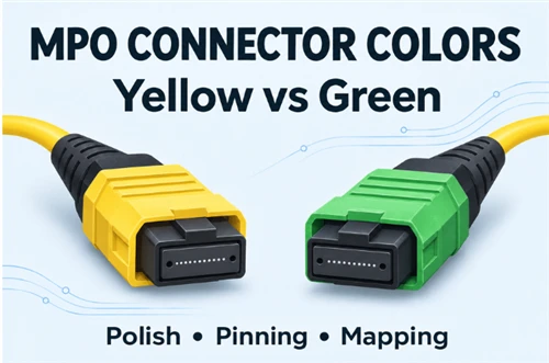
A green MPO-to-LC harness needs replacing, but the proposed replacement has a yellow MPO housing. Both have blue LC connectors. Can the yellow assembly take its place?
MPO connector colors help identify a product within a manufacturer's range. In some single-mode series, yellow identifies a low-loss grade and green identifies a standard APC grade. Green housings also appear on MTP Elite components. To approve a replacement, compare the actual interfaces, pinning, populated positions, fiber map and optical requirements. Any color change must also meet the project's identification and drawing requirements.
This question comes up in practice: a data-center technician's forum post describes green or yellow MPO connectors leading to blue LC duplex pairs. The published manufacturer examples below explain that combination.
What Do Yellow and Green MPO Connectors Mean?
The meaning depends on the product series. These examples show why a color code needs its manufacturer's name beside it.
Table 1. Manufacturer-specific yellow and green MPO examples
| Manufacturer / series | Published color meaning | What the example establishes |
|---|---|---|
| Sumitomo Lynx-CustomFit MPO | Yellow: single-mode low loss. Green: single-mode standard. Both are APC. | Color distinguishes loss grades within this series, rather than APC from UPC. |
| SENKO MPO-PLUS 702, datasheet p. 3 | Y: SM Low Loss Yellow. G: APC Green. | Housing color, ferrule type, gender/pin and fiber count are separate ordering fields. |
| US Conec MTP PRO component 21782 | Green housing with single-mode MTP Elite performance listed. | A green housing can belong to an Elite-grade component. |
| Corning MTP Pro component 94-749-87-BPPRO | Green, single-mode, Elite Pre-Angled. | Confirms another green Elite component listing; a component kit is not a finished-jumper test report. |
The Sumitomo product table gives a useful numerical example: maximum insertion loss is listed as ≤0.35 dB for its yellow low-loss grade and ≤0.75 dB for its green standard grade; both list return loss ≥60 dB. These are specifications for that series. The page does not fully describe the measurement conditions alongside the table, so those values should not be treated as universal yellow/green thresholds.
Identify the Housing, Boot and Cable Jacket First
Start by naming the part you are looking at. A connector housing, its strain-relief boot and the cable jacket can have different colors on the same assembly.
For example, CommScope UNGMWLUCK lists green MPO housings, black MPO boots, yellow jackets and blue LC housings and boots. That product is a 72-fiber fanout with six MPO connectors; it is cited here for its color and interface fields, not as a four-pair harness specification.

Figure 1. Parts of an illustrative eight-fiber MPO-to-LC harness. The inset distinguishes twelve ferrule positions from eight populated positions. This schematic does not depict a specific manufacturer's part.
Table 2. Read each colored part against its own record
| Part | A useful observation | Where to confirm it |
|---|---|---|
| MPO housing | Yellow or green may identify a grade within a named series. | Exact ordering code and connector datasheet. |
| MPO boot | Black also appears on single-mode MPO assemblies. | Assembly record; do not infer OM2 from this boot alone. |
| Cable jacket | Yellow is used for the single-mode assembly cited above. | Printed fiber designation and approved cable specification. |
| LC housing and boot | Blue corresponds to LC/UPC in the cited CommScope build. | The LC interface field for the actual part. |
| Dust cap | Identifies a protective accessory. | Connector configuration must come from the part record. |
Our general fiber color-code guide covers broader identification conventions. Check the connector family before applying a single-fiber connector table to an MPO boot.
How to Verify an Elite or Low-Loss Claim
MTP and MTP Elite are US Conec brand terms. A supplier offering another brand's low-loss MPO should identify that connector and its performance specification by its own name.
The US Conec FAQ explains that both the ferrule kit and housing kit must meet the required grade. Termination, polishing, spring force and end-face cleanliness also affect the finished connector's performance. A grade on the component bill of materials therefore needs to be accompanied by the required finished-assembly records.
When comparing quotations, check:
- Maximum insertion loss and the scope of that limit: a connection, an assembly path or an installed channel.
- Return loss as a separate requirement, with the measurement scope identified.
- Test wavelengths, reference method, mating configuration and per-fiber results.
- Whether values describe typical performance, a specified maximum, or a random-mating distribution.
Compare figures only after confirming that their test bases are compatible. Where the methods differ or are not stated, obtain the missing information before ranking the offers. For the broader brand-versus-interface distinction, see MPO vs MTP pre-terminated fiber.
Why Can an MPO/APC Breakout End in LC/UPC?
Each end connects to its own mating interface. The MPO/APC end can meet a compatible MPO/APC port or connector; each LC/UPC end can meet a compatible LC/UPC port or connector. The optical fibers run between these terminations.
The CommScope fanout cited above lists MPO-12/APC female interfaces at one end and LC/UPC at the other. That is evidence of different termination types at opposite ends of an assembly. It does not describe an APC face pressed against a UPC face at one connection.

Figure 2. One representative path through a breakout. Each mating pair is checked locally. The lower sketches compare matched APC, matched UPC and an APC/UPC mismatch; geometry is exaggerated for clarity.
At a physical connection, the polish and applicable interface geometry must match. MPO connections also require compatible keying and pinning. An adapter does not make an unsuitable pair acceptable merely because both plugs fit into it. Fluke's MPO guide explains why connector type and end-face geometry matter for inspection and testing.
A passive harness distributes optical paths. The module datasheets and system configuration must separately support the intended lane arrangement, wavelength and breakout mode.
Verify an MPO-to-LC Replacement in Six Steps
Use the same approved drawing and acceptance specification to assess the existing assembly and its proposed replacement.
Table 3. Replacement checks and decision criteria
| Check | Condition required for approval | Hold or reject when… |
|---|---|---|
| 1. Equipment and ports | Both-end module records identify compatible optical interfaces and support the intended breakout arrangement. | Hold if module compatibility is unconfirmed; reject a confirmed unsupported arrangement. |
| 2. Fiber and occupied positions | Fiber category, MPO family, populated positions and LC duplex count match the approved design. | Reject a confirmed mismatch; hold if only a generic "8-fiber" or "12-fiber" label is available. |
| 3. Polish at each connection | Each connector meets the required polish and interface geometry of its mating counterpart. | Reject a confirmed APC/UPC mismatch; hold if either end's polish is unspecified. |
| 4. MPO pinning | A conventional MPO mating pair has one pinned and one unpinned connector, with the required interface dimensions. | Reject a pin-to-pin or hole-to-hole pairing; hold if the actual port pin state is unknown. |
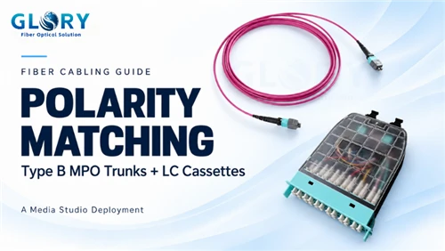
| 5. Keying and fiber map | Key arrangement and every MPO-position-to-LC-leg connection agree with the approved drawing and Tx/Rx assignment. | Reject an incorrect map; hold if only a polarity-method name is supplied without the needed branch map. |
| 6. Condition and performance | End-face checks and the optical measurements required by the project meet the specified limits and test basis. | Hold for inspection, cleaning or missing results; correct or replace a confirmed nonconforming assembly under the project procedure. |
For pinning, the alignment pins on one connector enter the guide holes on its mate, as described by VIAVI's MPO testing guide. Confirm the equipment interface rather than assuming every port uses the same pin state. Isolate the optical source before examining an exposed interface.
Use inspection tips appropriate to the connector and its polish. IEC 61300-3-35:2022 states that visual inspection supplements, rather than replaces, attenuation, return-loss and end-face parameter measurements. A clean image alone does not establish a loss grade or resolve an uncertain polish specification.
Example: Approve, reject or hold a yellow replacement
The following is a hypothetical review exercise. Its drawing assignments, limits and results are invented to demonstrate the decision process; they are not Glory test data or industry-wide acceptance limits.
Assume the project has already confirmed compatible modules and requires an OS2 harness with an unpinned MPO-12/APC plug facing a pinned MPO/APC interface, plus four LC/UPC duplex pairs. The approved drawing populates MPO positions 1–4 and 9–12, leaving 5–8 unused.
Table 4. Fiber map specified for this example
| LC duplex pair | LC position A connects to MPO position | LC position B connects to MPO position |
|---|---|---|
| 1 | 1 | 12 |
| 2 | 2 | 11 |
| 3 | 3 | 10 |
| 4 | 4 | 9 |
Position numbers refer to the example drawing's view into the MPO mating face, key up; LC A/B labels are also defined by that drawing. This is a specified harness map, not a universal mapping inferred from "Type B." Confirm its Tx/Rx relationship against the actual modules.
For this exercise, the project specifies end-to-end insertion loss ≤0.80 dB for each of the eight paths at both 1310 and 1550 nm, MPO-interface return loss ≥60 dB and LC-interface return loss ≥50 dB, using its agreed test procedures and compatible reference interfaces.
Table 5. Three candidate outcomes under those assumptions
| Candidate | Review evidence | Decision |
|---|---|---|
| A: yellow housing | Interfaces, unpinned MPO, occupied positions and all eight connections match. Assume inspection passes, worst path insertion loss is 0.58 dB across both wavelengths, and minimum measured MPO/LC interface return loss is 63/54 dB. | Eligible for approval after recording the color variation and obtaining any required drawing or customer acceptance. |
| B: yellow housing | MPO is pinned and would face the project's pinned interface. | Reject this configuration before attempting to connect it. A lower advertised loss cannot correct the pin mismatch. |
| C: yellow housing | Nominal interfaces match, but the supplier provides no MPO-to-LC leg map or per-path verification. | Hold for the missing records. Color and a headline loss rating do not resolve the mapping. |
Candidate A is suitable for the next approval step because the specified configuration and performance checks are satisfied under the example assumptions. The authorized reviewer must still accept the color change if color is controlled by the project. For existing trunk and channel-budget questions, use our MPO trunk reuse guide.
Glory MPO Products for the Confirmed Configuration
Choose the product family for the optical path, then include its exact interfaces and fiber map in the order.

Single-mode LC fanout
MTP to LC Breakout Cable
A single-mode harness family for taking an MPO-format distribution connection to LC duplex circuits. Choose the required branch count and leg lengths for the port schedule.
Specify MPO pinning and polish, LC polish, the number of duplex pairs and the complete MPO-to-LC leg map.

Single-mode backbone
OS2 MPO Multi-Connector Trunk Cable
An OS2 APC trunk family that groups fibers into Base-12 connector units at each end. Use it for the shared backbone upstream of separately selected LC fanouts or distribution modules.
Specify total fiber count, the gender of both ends, polarity and connector-group labels.

Multimode patching
OM4 MTP-12 UPC Female-to-Female Jumper
A 12-fiber OM4 jumper with female UPC ends and Type B polarity, for compatible multimode patching between equipment, panels or cassettes.
Confirm OM4 fiber, matching pinned UPC interfaces and the complete channel map before selecting the length.
Put the Confirmed Configuration in the RFQ
Send the supplier the actual module interfaces and the approved connection drawing. The request should identify:
| RFQ item | Required detail |
|---|---|
| Application | Module part numbers, link purpose and supported breakout mode. |
| Cable | Fiber category, overall length, leg lengths and required jacket rating. |
| MPO end | Interface family, total and populated positions, polish, pin state and key arrangement. |
| LC ends | Polish, duplex-pair count, leg labels and complete MPO-to-LC map. |
| Acceptance | Maximum path loss, interface return-loss requirements, wavelengths, test procedures and records. |
| Identification | Component and assembly part numbers, drawing revision, colors and any permitted substitutions. |
A permitted color variation must be documented against the project's identification requirements. It should never conceal a change to the connector, ferrule, fiber map or approved performance specification.
Request a configuration review and quotation from Glory Optical. Include the existing assembly's part number, interface diagram and required fiber map so the proposed build can be checked before ordering.
Frequently Asked Questions
Can a yellow MPO connector also be APC?
Yes. The Sumitomo series in Table 1 uses APC for both its yellow low-loss and green standard single-mode grades. Check the actual series before assigning a meaning to the housing color.
Does a black MPO boot identify OM2 fiber?
No reliable conclusion follows from that boot alone. The cited CommScope single-mode assembly uses black MPO boots. Use the printed fiber designation and part record.
Can different-colored MPO and MTP connectors mate?
They can when their actual interfaces are compatible. Verify connector family, polish, pinning, keying and the required fiber map; then check the optical requirements. MTP is a US Conec brand of MPO connector, not a color-based compatibility category.
Is a "Type B" label enough to order the breakout?
For a replacement that depends on specific LC legs, obtain the position-to-leg drawing as well. The label alone does not show every branch assignment or the conventions used to number the ends.
Does an MPO-to-LC harness guarantee that a switch supports breakout?
No. The harness supplies passive optical paths. Supported module types, lane arrangements and switch configuration must be confirmed separately.
MTP and MTP Elite are registered trademarks of US Conec Ltd. Manufacturer records were checked on November 4, 2026.