Short answer. In the design example below, one 12-fiber Type B MPO trunk, two LC cassettes and twelve duplex LC jumpers carry six independent 10G links. Each link passes through three pair swaps: one in each A-to-B jumper and one in the trunk. Three is an odd number, so in this configuration every transmitter meets a receiver. Which port meets which depends on the cassette pair. The example uses identical in-order cassettes, where port n meets port 7 − n; section 3 covers the n-to-n case.
1. The Deployment Brief: Six Workstation Links from Machine Room to Edit Suite
This walkthrough follows an illustrative design scenario built to show the decisions in a Type B MPO deployment.
A media production team keeps its shared storage and 10G switch in a machine room. Six editing workstations sit in an edit suite on the same floor. The example allocates a 60 m installed trunk, including service slack; the actual tray route must be surveyed before ordering. Each workstation needs its own 10G link to the switch, using 10GBASE-SR optics over OM4 multimode fiber. The standard reaches 300 m on OM3 and 400 m on OM4 (Ethernet Alliance), so length leaves ample headroom. The constraint to manage is connector loss, which section 8 works through.
Six separate duplex cables mean six runs to pull, label and maintain. A single 12-fiber MPO trunk carries all six links in one pull, while LC cassettes at each end keep the familiar LC interface at the switch and at the workstation patch point. Replacing a jumper or a cassette later leaves the trunk undisturbed.
Table 1. Where each component sits
| Location | What is installed | Role |
|---|---|---|
| Machine room rack | Switch, cassette panel with cassette A, LC jumpers | Gathers six separate optical ports into one MPO connection |
| Cable tray route | 12-fiber Type B MPO trunk | Carries the fibers for all six links |
| Edit suite patch point | Cassette panel with cassette B, port labels | Distributes trunk fibers to individual workstation links |
| Workstation | LC jumper, fiber NIC, SFP+ SR module | Completes each workstation's network connection |
Figure 1. Machine Room to Edit Suite

The shared trunk connects two patching locations; each workstation retains its own duplex link.
On small screens, swipe the diagram horizontally to read all labels.
2. Cabling Architecture: What Is Shared and What Belongs to Each Link
One link, end to end:
Switch SFP+ port → LC jumper → cassette A → Type B trunk → cassette B → LC jumper → workstation SFP+ port
The trunk and the two cassettes are shared by all six links. The two jumpers, the switch port and the workstation port belong to one link. Twelve fibers carry six duplex links, and each link needs two LC jumpers, giving twelve.
Table 2. Bill of materials for the example
| Component | Quantity | Note |
|---|---|---|
| 12-fiber Type B MPO trunk, OM4 | 1 | About 60 m installed, including service slack |
| MPO-12 to 6× duplex LC cassette, OM4 | 2 | Same fiber grade as trunk |
| Rack-mount cassette panel | 2 | Must accept the chosen cassette footprint |
| Duplex LC jumper, A-to-B, OM4 | 12 | Six per end; 2.5 m each assumed |
| SFP+ SR module (850 nm) | 12 | Six in the switch, six in workstation NICs |
The switch and the six workstation NICs, with SFP+ cages, are assumed to be existing equipment. All twelve fibers are assigned. If expansion is likely, plan additional trunk and cassette capacity before installation. Fiber grade must match throughout: OM4 trunk, cassettes and jumpers with 850 nm optics.
 |
Glory product OM4 MPO Fiber Patch CordMPO-to-MPO connectivity for the shared fiber route. Specify 12 populated fibers, Type B mapping, gender and finished length. View MPO Cable |
3. Matching a Type B Trunk to Its Cassettes
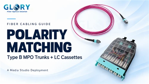
TIA defines three MPO trunk types. Type A is straight-through, with position 1 arriving at position 1. Type B has key-up connectors at both ends and reverses the array: position 1 arrives at 12, position 2 at 11, and so on. Type C flips each adjacent pair. Methods A, B and C then combine a trunk type with matching adapters and jumpers.
This deployment uses Method B: a Type B trunk, cassettes whose rear adapters hold the trunk key-up to key-up, and standard A-to-B duplex jumpers at both ends (TrueCable). A cassette labeled for another method cannot be swapped in without changing the system.
Cassette pairs vary by manufacturer, and the variation changes the port map. FS, for example, lists Type B1 and B2 cassettes that pair for Method B (B2 reverses the fiber sequence, so its port 1 uses positions 11 and 12) and a Universal cassette for both ends of a Method B trunk (port 1 uses positions 1 and 12) (FS datasheet). Following that mapping through a Type B trunk, port n meets port n. An identical in-order pair, where port n carries fibers 2n − 1 and 2n, puts port n at port 7 − n. This walkthrough uses the in-order pair, and Table 5 documents only that configuration. Universal cassettes use different fiber groups, so their internal paths must be traced separately. Ask the supplier for a polarity drawing before ordering.
Table 3. Matching checks before ordering
| Item | Match to confirm | Evidence to request |
|---|---|---|
| Trunk type | Type B, key-up at both ends | Polarity statement and fiber-position drawing |
| Cassette method | Method B, rear adapter key-up to key-up | Cassette drawing marked with the method |
| Cassette numbering | Identical in-order pair for this example; confirm the supplied variant | Complete port-to-fiber table and installation orientation |
| MPO gender | One pinned end and one unpinned end per mating | Gender of trunk ends and cassette rear ports |
| Fiber and loss grade | Same fiber type; insertion loss grade stated | Datasheet and test report |
| Jumpers | Duplex A-to-B at both ends | Jumper drawing |
MPO connectors come pinned or unpinned, and a pinned end must mate with an unpinned end (Photonics). Many cassettes carry a pinned rear MPO, which calls for an unpinned trunk end, but vendors differ, so confirm against the drawing.
 |
Glory product GL-07 MPO Fiber Distribution BoxRelated housing option for MPO-to-LC distribution. Published 24-fiber family; confirm the internal map and panel fit. View GL-07 Box |
4. Installing and Labeling Both Ends
Machine room end. Mount cassette A in its rack panel and note which port the drawing calls port 1. Inspect the trunk's MPO end and the cassette's rear port, clean only an end face that fails, and inspect again after any cleaning (Fluke Networks). Mate them, then patch SW-01 to A1 with an A-to-B jumper, SW-02 to A2, and so on through A6. Label each jumper end with its link ID, L1 to L6, taken from the switch port.
Edit suite end. Mount cassette B and repeat the inspect, clean if needed, re-inspect routine. Label its ports B1 to B6 and assign workstations from the port map in section 6. Each workstation jumper carries the same link ID as the switch end.
Print the final port map and fix it inside each panel door. Record the trunk type, cassette variant, part numbers and drawing revision on the panel schedule. A Method B label alone does not identify a cassette's internal map.
Figure 2. Patching at Both Ends

Switch ports SW-01–SW-06 connect to A1–A6. The in-order cassettes produce reversed port assignments at cassette B.
On small screens, swipe the diagram horizontally to read all labels.
 |
Glory product MPO Patch PanelRack-mounted housing for modular fiber patching. Confirm cassette footprint, loading and access before selecting the panel. View Patch Panel |
5. Tracing the First Link in Both Directions
The trace uses the identical in-order cassette pair. Take link L1: switch port SW-01 to the workstation on cassette port B6. Each cassette port follows the same pattern: port n takes trunk fibers 2n − 1 and 2n, so port 1 takes fibers 1 and 2, and port 6 takes fibers 11 and 12. In this walkthrough, an A-to-B jumper places a transceiver's transmit side on the second connector of a cassette port and its receive side on the first. Both jumpers are the same type, so the rule holds at both ends.
Table 4. Tracing L1 in both directions
| Step | Switch to workstation | Workstation to switch |
|---|---|---|
| 1 | Switch Tx reaches cassette A port 1, second connector (fiber 2) | Workstation Tx reaches cassette B port 6, second connector (fiber 12) |
| 2 | Trunk carries fiber 2 to position 11 | Trunk carries fiber 12 to position 1 |
| 3 | Position 11 is the first connector of cassette B port 6 | Position 1 is the first connector of cassette A port 1 |
| 4 | Jumper delivers the signal to the workstation Rx | Jumper delivers the signal to the switch Rx |
Both directions arrive at a receiver. The A-to-B jumper at the switch end swaps the transmit and receive positions once. The Type B trunk reverses the array and swaps them a second time. The A-to-B jumper at the workstation end swaps them a third time. A duplex link needs an odd number of swaps to turn a transmit position into a receive position. Two or four swaps would return transmit to transmit, and both receivers would stay dark.
The jumpers set the swap at the equipment edge, the cassettes keep the pair order, and the trunk supplies the reversal in the middle. A different map can change port order, pair polarity, or both; it does not necessarily change the swap count. A like-for-like replacement preserves the mapping. B1/B2 and Universal pairs require their own complete path traces.
Figure 3. L1: Transmit and Return Paths

L1 uses positions 2→11 for switch transmission and 12→1 for the return path.
On small screens, swipe the diagram horizontally to read all labels.
6. Bringing the Other Five Workstations Online
Because the trunk reverses the array, an identical in-order pair puts the port numbers at the two cassettes in opposite order: port n at cassette A meets port 7 − n at cassette B. Naming each workstation after its cassette B port keeps the labels simple. For a different cassette configuration, issue its own approved port map before assigning workstation labels.
Table 5. Port assignment for the six links
| Link ID | Switch port | Cassette A port | Trunk fibers (A end → B end) | Cassette B port, in-order pair | Workstation, in-order pair |
|---|---|---|---|---|---|
| L1 | SW-01 | A1 | 1, 2 → 12, 11 | B6 | Edit-06 |
| L2 | SW-02 | A2 | 3, 4 → 10, 9 | B5 | Edit-05 |
| L3 | SW-03 | A3 | 5, 6 → 8, 7 | B4 | Edit-04 |
| L4 | SW-04 | A4 | 7, 8 → 6, 5 | B3 | Edit-03 |
| L5 | SW-05 | A5 | 9, 10 → 4, 3 | B2 | Edit-02 |
| L6 | SW-06 | A6 | 11, 12 → 2, 1 | B1 | Edit-01 |
Bring links up one at a time: connect the jumpers, confirm link status and module diagnostics at both ends, and record the result against the map. Confirm the destination as well as the light by unplugging the workstation jumper and checking that the named switch port drops.
Figure 4. Panel-Door Port Schedule

Panel-door worksheet based on Table 5, with tested/date/initials fields. Use only with the matching in-order cassette configuration.
On small screens, swipe the diagram horizontally to read all labels.
7. When a Link Stays Dark: A Field Troubleshooting Order
Work from the quickest checks outward.
- Equipment and optics. Confirm both ends use 850 nm SR modules, the NIC accepts the module, and both ports are enabled. Read transmit and receive power from module diagnostics where available.
- End faces. Inspect every connector involved, clean only end faces that fail (IEC 61300-3-35 is a common criterion), and re-inspect after each cleaning (Fluke Networks). Contamination can hide the real fault (Computer Cable Store).
- LC jumpers. Reverse the two fibers of the duplex jumper at one end (re-seat its LC connectors in swapped positions, or substitute the opposite A-to-B or A-to-A type). If the link comes up, investigate polarity, but confirm the cause against the complete map: the change may compensate for another component, and reseating can also affect contact quality. Treat the link as unresolved until steps 4 and 5 are checked (FS).
- Cassette mapping. Compare the cassette's type, markings and port numbering with the supplier drawing.
- Trunk mapping. Verify all twelve positions with an MPO polarity tester, or trace each fiber, confirming that position 1 arrives at 12, position 2 at 11, and so on through position 12 at 1.
Two illustrative fault examples follow.
Wrong jumper. Replace one A-to-B jumper on L1 with an A-to-A jumper. The swap count falls from three to two, transmitters meet transmitters, and both receivers stay dark. Reinstalling the A-to-B jumper restores the link.
Lit, but in the wrong place. Suppose the machine room has an in-order cassette and the edit suite has a reverse-numbered B2-style cassette. Links still light, but L1 now emerges at port B1 instead of B6. A technician following the in-order column of Table 5 patches Edit-06 into what is now L6, so the workstation reaches the wrong switch port. The optics look healthy while addressing or VLAN settings fail, which is why the destination check in section 6 matters.
8. Acceptance, Handover and Project Inquiry
Stage 1: the trunk. Before connecting jumpers, test the trunk as MPO-terminated cabling with MPO-interface equipment. IEC 61280-4-5 covers attenuation, polarity and length for such cabling, and TIA-568.3-E added MPO test requirements that reference TIA-526-28, an adoption of it, including gender-neutral MPO test cords (VIAVI). The IEC standard does not cover cabling that is not exclusively MPO-to-MPO (IEC), so it applies to the bare trunk, not the finished LC links.
Stage 2: the six links. With cassettes and jumpers in place, test each link end to end with a duplex LC test set and LC reference cords, using the method in your test plan (for multimode, such as IEC 61280-4-1). Tier 1 under TIA-568.3 covers loss, length and polarity, so each link's report should show all three.
The handover pack should contain:
- the final port map and photographs of both labeled panels;
- part numbers and the polarity method for the trunk, cassettes and jumpers;
- end-face inspection records taken before mating;
- the Stage 1 trunk report and Stage 2 reports for all six links.
Loss arithmetic shows why component grade matters. The channel has four mated pairs: jumper to cassette at each end (two LC) and trunk to cassette at each end (two MPO). The connections between jumpers and transceivers lie outside the channel reference plane (Fluke Networks). Fiber length is about 65 m (60 m of trunk including slack plus two 2.5 m jumpers), which adds about 0.23 dB using a conservative design allowance of 3.5 dB/km at 850 nm. 10GBASE-SR allows a channel insertion loss of 2.9 dB on OM4 and 2.6 dB on OM3 (TIA FOTC); the table shows both, with the OM3 figure as a stricter reference. The per-pair values are placeholders; use the maxima for each cassette's actual MPO and LC interfaces.
Table 6. Illustrative loss budget (design arithmetic, not measured)
| Loss per mated pair | Four mated pairs | Plus 65 m fiber | Margin against 2.9 dB (OM4) | Margin against 2.6 dB (OM3) |
|---|---|---|---|---|
| 0.35 dB | 1.40 dB | 1.63 dB | about 1.3 dB | about 1.0 dB |
| 0.50 dB | 2.00 dB | 2.23 dB | about 0.7 dB | about 0.4 dB |
To check a configuration for your own project, send Glory Optical Communication your link count, route length, fiber grade, transceiver models, polarity method, panel type and MPO gender. The technical team can review them against a trunk, cassette and jumper set and return a port map and polarity drawing for approval.
Confirm the trunk, cassette and jumper configuration before ordering.
Discuss Your Cabling ProjectTechnical References
- 10GbE Standardized to 400 Meters on OM4 Fiber (Ethernet Alliance)
- Polarity in MTP®/MPO Fiber Cabling Applications (trueCABLE)
- FHD Base-12 MTP®-LC/SC/MDC Cassettes - Datasheet (FS)
- Testing and Maintaining Not-Quite-Plug-and-Play MPO Connectors (Photonics Spectra)
- Fiber Contamination, Cleaning, and Inspection: An Introduction - White Paper (Fluke Networks)
- Practical Guide to Managing Polarity in MPO/MTP Systems (Computer Cable Store)
- Polarity Validation for MTP/MPO Cables (FS)
- Everything You Need to Know: TIA Standard Adds MPO Test Requirements and Procedures (VIAVI Solutions)
- IEC 61280-4-5:2020 - Attenuation Measurement of MPO-Terminated Fibre Optic Cabling Plant Using Test Equipment with MPO Interfaces (IEC)
- IEC 61280-4-1:2019+AMD1:2021 - Installed Cabling Plant: Multimode Attenuation Measurement (IEC)
- Demystifying Fiber Test Methods - Back to Basics (Fluke Networks)
- 10GBASE-SR Application Overview (TIA Fiber Optics Technology Consortium)