The Quick Answer
An ODN fiber optic solution is not a single product - it is the complete passive path from the OLT to the ONT, built in three working segments. The feeder layer runs high-count G.652D outdoor cable from the central office to a primary node. The distribution layer routes split fibers through closures, PLC splitters and FDB/NAP boxes toward subscriber clusters. The drop layer carries bend-insensitive G.657A2 cable to each premises, ending in a termination box, pigtail and wall outlet. Design the three segments together, size the split ratio against a calculated link budget, and reserve spare ports so the ODN is easier to expand, test and maintain after day-one activation.
This guide treats the ODN as a single engineering system rather than a parts list. The full chain is OLT / CO → feeder cable → splice closure → PLC splitter → distribution cable → FDB / NAP → drop cable → ONT. Every node in that chain has a defined function, a physical location and a test boundary. Clear boundaries make troubleshooting faster; unclear port records, extra mating points or dirty connectors make field isolation harder than it needs to be.
Use this page to convert a network topology into a procurement-ready ODN BOM. Planning values such as splitter insertion loss, connector-pair loss, IP rating and cable tensile load must still be confirmed against the actual product datasheet, the OLT/ONT specification and the operator's acceptance rules.
ODN RFQ and BOM Input Checklist
For procurement teams, the fastest way to turn an FTTH design into a usable ODN bill of materials is to send the network inputs in one package. A supplier cannot size the feeder cable, splitter package, FDB capacity or drop-cable type from subscriber count alone; the route, split plan and installation environment must be checked together.
| Input to provide | Why it matters | Example format |
|---|---|---|
| Route distance | Sets fiber attenuation and helps confirm whether the split ratio can stay inside the optical budget. | Feeder 8 km + distribution 1.5 km + drop 80 m |
| Subscriber count and take-rate target | Determines FDB/NAP port count, splitter ratio, spare ports and spare fibers. | 320 homes passed, 45% day-one activation, 20% spare capacity |
| Split plan | Separates centralized 1:32 designs from cascaded 1:4 × 1:8 or 1:8 × 1:8 designs. | Single-stage 1:32 or two-stage 1:4 + 1:8 |
| Installation environment | Changes cable construction, enclosure material, sealing level and mounting accessories. | Aerial pole, underground duct, handhole, direct-burial or building riser |
| Connector and testing rules | Defines pigtail, adapter, patch-cord and acceptance-test requirements. | SC/APC, 1310/1550 nm OLTS, OTDR trace, IEC 61300-3-35 inspection |
| OEM requirements | Confirms whether labels, packaging, cable printing, box color or kit grouping must be customized. | Private label, carton mark, port label, project kit by building |
For OEM/ODM ODN projects, Glory Optical reviews the passive chain as a matched set rather than as isolated SKUs. The review normally checks whether the splitter package, FDB tray capacity, adapter count, closure sealing, drop-cable construction, port labeling and export packaging all follow the same port map and link-budget assumption. Final production values should still be locked by the approved drawing, datasheet and pre-shipment test record.
This article uses conservative planning values for early BOM discussion. Final approval should be based on the selected OLT/ONT optical class, splitter datasheets, cable attenuation, measured connector loss, splice records and the operator's acceptance standard. Where a value is marked as an example, do not copy it directly into a project design without recalculation.
The Full FTTH ODN Link: From OLT to ONT
The Optical Distribution Network is the passive portion of a PON between the OLT in the central office and the ONT at the customer. In practical FTTH planning, it is the field-built path made from feeder cable, splice closures, PLC splitters, distribution cable, FDB/NAP boxes, drop cable and subscriber-side termination. Because the path is passive, it carries no field electronics to power or maintain - but every splice, splitter and connector pair permanently consumes part of the optical budget. There is no downstream amplifier to recover a margin lost to an avoidable extra mating point.

| Node | Function in the ODN | Typical components | Quality checkpoint |
|---|---|---|---|
| OLT side / CO | Active launch point; feeder fibers patched out of the ODF | ODF, feeder patching, optical ports | Port mapping and transmit-power record per PON port |
| Feeder + primary node | Backbone transport and first passive split or major splice | High-count outdoor cable, dome closure, primary PLC splitter | Splitter loss, input/output labels, closure sealing, baseline OTDR |
| Distribution point | Routes split fibers toward subscriber clusters | Distribution cable, FDB / NAP box, optional secondary splitter | Port assignment, splice-tray routing, adapter cleanliness, spare ports |
| Drop + premises entry | Transitions from outdoor drop to the subscriber side | G.657A2 drop cable, termination box, pigtail, wall outlet | Bend radius, strain relief, connector inspection before mating |
Feeder, Distribution and Drop: How the Three Segments Divide the Work
The most useful way to think about an ODN solution is by mechanical risk, not by product name. Each segment fails differently, so each is engineered differently. A common engineering mistake is ordering one cable type for the whole route; the feeder, distribution and drop segments each face a distinct dominant stress.
Feeder layer - transport under tension
The feeder is the high-fiber-count backbone from the OLT/CO to a cabinet, primary splice closure or Fiber Distribution Hub. Corning notes that placing the splitter at a centralized hub lets a lower-count feeder serve many homes, which reduces upfront splicing labor and build time compared with running individual fibers to every subscriber. The dominant risk here is tensile load during the pull and long-term span tension on aerial routes, so feeder selection is driven by fiber count, tensile rating and duct or span condition. Glory Optical typically specifies G.652D in GYXTW, GYTA or ADSS construction for this segment.
Distribution layer - routing and records
The distribution segment carries split fibers from the primary node out to street-level or building-entry FDB/NAP boxes. This is where port discipline lives or dies. The dominant risk is not mechanical but organizational: unlabeled ports, no spare capacity and poor splice-tray routing. A modular fiber distribution box for last-mile access with reserved adapter ports is what lets an operator add subscribers later without a full node rebuild.
Drop layer - the bend-sensitive last span
The drop is the 1–4 fiber run from the FDB/NAP to the premises and is the most bend- and handling-sensitive part of the network. Wall entries, clamps, rosettes and the final 90-degree turn all impose tight bends, which is exactly why ITU-T G.657 bend-insensitive fiber exists. Use flat self-supporting drop for short aerial spans and round drop for ducts and protected underground routes. The standard design pattern is G.652D in the feeder and distribution network, then G.657A2 from the FDB to the subscriber.
| Segment | Dominant risk | Typical fiber / cable | Selection check |
|---|---|---|---|
| Feeder CO to primary node | Tensile load, span tension | G.652D, GYXTW / GYTA / ADSS, 12–144 fibers | Fiber count, tensile rating, spare capacity, duct/span design |
| Distribution Primary node to FDB | Sealing, port records, expansion | G.652D loose-tube distribution cable, 6–48 fibers | Subscriber density, split plan, spare ports, box IP rating |
| Drop FDB / NAP to premises | Bending, handling damage | G.657A2, 1–4 fibers, flat or round drop | Span/route type, tensile load, minimum bend radius, entry angle |
Split Ratio: How 1:8, 1:16, 1:32 and 1:64 Drive Coverage and Budget
Split ratio is the single decision that most strongly couples coverage to optical budget. In planning terms, every time the number of branches doubles, the splitter consumes about 3 dB more optical power. That extra loss buys more subscribers per OLT port, but it also shortens the usable reach and leaves less margin for connectors, splices, aging and repair reserve. This is why the split ratio should be selected after the link budget is calculated, not simply copied from a previous project.
| Split ratio | Typical insertion loss (planning) | Subscribers per feeder fiber | Where it fits |
|---|---|---|---|
| 1:8 | ~10.5 dB | 8 | Second stage of a cascade; low-density or long-reach drops with budget to spare |
| 1:16 | ~13.8 dB | 16 | Long-reach rural runs where distance, not density, is the constraint |
| 1:32 | ~17.5 dB | 32 | The common residential / small-business balance of reach, density and budget |
| 1:64 | ~21 dB | 64 | High-density urban builds with short feeders and a verified budget margin |
The temptation is always to spec the highest ratio "to be safe" on port count. In practice, oversized split ratios are a primary source of FTTH instability: when the margin is squeezed too aggressively, connector aging and temperature swing eat the remaining headroom, and the subscribers at the end of the tree become the ones who call support during peak hours. Choose the ratio after the budget math, not before.
Single-Stage vs Two-Stage Splitting
The same overall split can be reached two ways, and the choice is an operations decision, not just a product choice. In a single-stage (centralized) design, one splitter - often 1:32 - sits in a cabinet or FDH and feeds subscribers directly. Records are simple and the loss is concentrated at one well-controlled point, which is why this approach is favored in dense city centers where maintenance access is easy.
In a two-stage (cascaded) design, splitting is divided across nodes - for example a 1:4 at the central office feeding four 1:8 terminals to reach 32 homes (4×8), or 1:8 + 1:8 to serve 64. Cascaded splitting is useful when subscribers are spread across villages, curbside terminals or widely separated building groups. Centralized splitting is easier to document and maintain in dense urban areas. Two-stage designs improve fiber economy and subscriber clustering, but they add physical nodes you must document and test, and they stack splitter loss (for example, 10.5 dB + 10.5 dB ≈ 21 dB for 64 homes).

Deployment Scenarios: Aerial, Underground, Duct and Direct-Burial
The same logical ODN can be built across very different physical environments, and the deployment method changes the hardware more than the topology does. Choosing the box IP rating, cable construction and sealing level for the actual environment is what keeps the network out of trouble after the first winter.
| Scenario | Typical hardware | Main risk to manage | Selection check |
|---|---|---|---|
| Aerial | ADSS / self-supporting feeder, flat drop, pole-mounted NAP, dome closure | Wind/ice span load, UV exposure, clearance | Span length, sag, attachment hardware, UV-stable enclosure |
| Underground (handhole / manhole) | Loose-tube armored cable, sealed inline/dome closure, below-grade FDB | Water ingress, flooding, rodent damage | Higher IP sealing (IP67/IP68), gel/blocking, splice-tray slack |
| Duct / micro-duct | Round drop cable, GYTS/GYFTY in conduit, micro-duct connectors | Pulling tension, duct continuity, duct sealing | Duct size, pull string, lubricant, end seals, water blocking |
| Direct-burial | Armored direct-burial cable, buried handholes, marker tape | Crush load, ground movement, dig-ups | Burial depth, armor type, route marking, utility-location coordination |
For outdoor and below-grade nodes, choose enclosures rated for the environment - typically IP65–IP68 in UV-resistant ABS, polycarbonate or die-cast aluminium with a working range around −40 °C to +85 °C. Flood-prone handholes need a higher sealing level than a sheltered wall box. An outdoor splice closure for ODN deployment that is under-rated for the location is the most common cause of slow, weather-correlated faults months after handover.
ODN Bill of Materials by Layer
A clean ODN BOM is organized by layer, not by a flat product list. Grouping it by feeder, distribution, drop and subscriber lets procurement, installation and QA each verify that every cable segment, passive node and test step has the right component - and that spare fibers and spare ports are actually in the order.

| ODN layer | Main components | Typical specification | Decision notes |
|---|---|---|---|
| Feeder OLT side to primary node | Outdoor feeder cable, dome splice closure, primary PLC splitter | G.652D, GYXTW / GYTA / ADSS, 12–144 fibers; IP67/IP68 closure | Confirm route length, spare fiber count, closure capacity and whether the primary splitter sits in a cabinet or closure. |
| Distribution Primary node to FDB / building | Distribution cable, inline closure, fiber distribution box, PLC splitter for FTTH ODN | G.652D, 6–48 fibers; FDB/NAP with SC/APC adapters and splice tray | Match port count to subscriber density, reserve ports for take-rate growth, raise sealing in exposed or below-grade locations. |
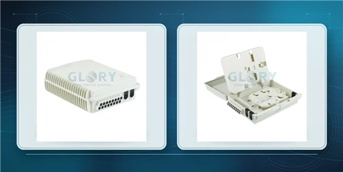
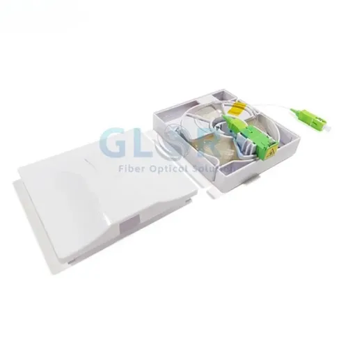
| Drop FDB / NAP to premises | FTTH drop cable, clamps, entry grommet, drop termination box | G.657A2, 1–4 fibers, flat self-supporting or round duct type | Flat drop for short aerial routes, round drop for ducts/underground. Verify tensile load and minimum bend radius. |
| Subscriber Premises entry to ONT | SC/APC pigtail, fiber wall outlet, ONT patch cord | OS2 / G.657A2, SC/APC, 1–3 m patch cord; indoor wall outlet or rosette | Protect connector endfaces until activation; inspect and clean before mating to reduce activation faults. |
| Testing support | VFL, OLTS, OTDR, inspection scope, cleaning tools, labels, records | 1310/1550 nm test set; IEC 61300-3-35 inspection; OTDR trace per span | Test gear and documentation are part of the deployment BOM, not an afterthought. |
Optical Link Budget: The Calculation That Sizes the Whole ODN
Every decision above - split ratio, feeder length, number of splices, connector count - converges on one number: the optical link budget. GPON Class B+ is commonly used as a ~28 dB planning reference, but the final allowable loss must come from the actual OLT/ONT optical class and operator rules. The ODN must fit fiber attenuation, splitter loss, connector pairs, splices and a reserve margin inside that limit. A practical FTTH design calculates the furthest-subscriber path first, keeps a defined safety margin and removes unnecessary mating points before hardware is ordered.
| System | Common budget class | Planning use | Important limitation |
|---|---|---|---|
| GPON | Class B+ (~28 dB) / C+ depending on equipment | Common residential and small-business FTTH | Actual Tx power, Rx sensitivity and margin rules vary by equipment. |
| XGS-PON | N1 / N2 depending on equipment | 10G symmetric upgrade or new build | The passive ODN is often reusable, but budget and coexistence still need device verification. |
Worked example only: 10 km GPON with 1:32 split

| Loss item | Planning calculation | Example value | Value type |
|---|---|---|---|
| Fiber attenuation | 10 km × 0.35 dB/km | 3.5 dB | Typical planning value |
| 1:32 splitter | Use selected splitter datasheet | ~17.5 dB | Typical industry value |
| Connector pairs | 4 pairs × 0.4 dB | 1.6 dB | Conservative planning value; verify by OLTS |
| Fusion splices | 6 joints × 0.05 dB | 0.3 dB | Typical value; verify by OTDR / splice record |
| Total calculated loss | 22.9 dB | Example only | |
| Margin vs 28 dB Class B+ | 28 − 22.9 | ~5.1 dB | Project-dependent reserve |
In this example, the remaining margin is only about 5 dB before repair reserve and field variation are considered. One extra field splice, an added connector pair, a second-stage splitter or a route extension can quickly reduce that margin. Treat the budget as a design constraint that sets the split ratio and feeder length, not as paperwork completed after the BOM is chosen.
Design Risk Scenarios: What Goes Wrong When the Budget Is Skipped
Budget problems usually appear before construction, if the BOM is reviewed carefully. The warning signs are simple: a high split ratio, a long route, several connector pairs, unconfirmed splice counts and no repair reserve. The section below is written as a design-review scenario, not as a named customer case, so the reader can apply the checklist to any FTTH project before ordering hardware.
Assume an FTTH project is submitted with a 10–15 km ODN route, a 1:32 split, several FDB/NAP nodes and only the splitter's typical insertion-loss value in the budget. The design may appear acceptable if connector pairs, field splices, dirty interfaces and repair reserve are not counted. Before accepting that BOM, the engineer should ask four questions: how many mated pairs are in the real path, how many splices are expected after route changes, which splitter value is guaranteed by the datasheet, and how much margin remains for the furthest subscriber after repair reserve.
- Red flag: the budget uses only typical splitter loss, not the selected splitter datasheet value.
- Red flag: the drawing shows extra patch points, but the loss table counts only one or two connector pairs.
- Red flag: the furthest subscriber has less than the operator's required margin after splices and repair reserve.
- Correction: recalculate the full path with measured or guaranteed values before fixing the split ratio, closure layout and FDB quantity.
A published design and implementation study of the Al-Gehad FTTH network describes a planned access network covering about 32 km² and 6,000 ONTs. The study uses a protected ring approach on the feeder side, 20% spare feeder capacity, first-level splitting at the FDT, and a star/tree distribution section with 72F / 48F / 24F / 12F cable stepping down toward FAT locations. It also reports 243 km of feeder cabling and 405 km of distribution cabling. The planning lesson is useful for OEM ODN BOMs: keep the feeder protected and well documented, step fiber count down by segment, and reserve capacity before the drop network is built.
Common ODN Design Mistakes
During activation and maintenance, many ODN problems trace back to design-review gaps rather than a defective component: uncounted connector pairs, unclear splice records, insufficient spare capacity, poor sealing choices or a link budget that was not recalculated after field changes. These issues are easier to prevent in the BOM than to correct after subscribers are connected.
| Mistake | Why it matters | Prevention |
|---|---|---|
| Too many split points | Stacked cascaded splitters add 3 dB per doubling and can blow the budget for end-of-tree subscribers. | Use the minimum split levels that meet density; keep cascade loss inside the calculated budget. |
| Too many splice/mating points | Every connector pair and splice adds insertion loss and a reflectance event that complicates OTDR traces. | Minimize unnecessary mating points; favor factory-terminated, tested assemblies. |
| No reserved ports or spare fibers | Take-rate growth forces a full node rebuild instead of a simple patch. | Size FDB/NAP port count and feeder fiber count above day-one demand. |
| No link-budget calculation | The furthest subscriber can fall below receiver sensitivity, as described in the risk scenario above. | Calculate fiber + splitter + connector + splice loss with a 3–5 dB margin before ordering. |
| Wrong fiber on tight drops | Standard G.652D suffers bend loss at wall entries and rosettes. | Use G.657A2 bend-insensitive drop cable on the last span. |
FAQ
Q: What does ODN stand for in fiber optics?
A: ODN stands for Optical Distribution Network. In FTTH, it means the passive fiber path between the OLT and the ONT: feeder cable, splitters, closures, distribution boxes, drop cable and subscriber-side termination.
Q: What is an ODN fiber optic solution for FTTH?
A: It is a complete passive access design, not one product. A practical ODN solution defines the feeder, distribution and drop layers, then matches cable type, splitter ratio, FDB/NAP capacity, connector type and test requirements to the route and link budget.
Q: How do feeder, distribution and drop segments divide work in an ODN?
A: The feeder carries higher-count cable from the CO or OLT area to the primary node. The distribution segment routes split fibers toward subscriber clusters through FDB/NAP boxes. The drop segment is the short, bend-sensitive run from the access box to the premises.
Q: How does split ratio affect coverage and optical budget?
A: A higher split ratio serves more subscribers per PON port but consumes more optical budget. As a planning guide, 1:32 is often used for balanced residential builds, while 1:64 needs shorter routes or stronger budget margin. Always check the selected splitter datasheet and OLT/ONT class.
Q: What products belong in an FTTH ODN BOM?
A: A complete BOM normally includes feeder cable, splice closures, PLC splitters, distribution cable, FDB/NAP boxes, G.657A2 drop cable, termination boxes, adapters, pigtails, patch cords, labels and test/cleaning support.
Q: What are the most common ODN design mistakes?
A: The common mistakes are undercounting connector pairs, adding too many split or splice points, leaving no spare fibers or ports, using the wrong enclosure rating for the environment, and fixing the split ratio before recalculating the link budget.
Q: Single-stage or two-stage splitting for an ODN?
A: Single-stage splitting is easier to document and maintain in dense areas. Two-stage splitting can save feeder fiber in scattered routes, but it adds field nodes and test points. The better choice depends on budget margin, subscriber density and maintenance access.
Q: Can the same ODN support GPON and XGS-PON?
A: Often yes, because the passive fiber and PLC splitters can carry the relevant wavelengths. The upgrade still requires verification of XGS-PON budget class, coexistence plan, ONT/OLT optics and remaining margin on the furthest subscriber path.
Q: What information is needed for an FTTH ODN BOM quotation?
A: Send route distance, subscriber count, split ratio, feeder and distribution fiber count, environment, closure or box location, required IP rating, connector type, cable construction, test rules and OEM packaging or label requirements.
Q: Which ODN components can be customized for OEM projects?
A: Common customization items include cable length and fiber count, splitter ratio and package style, FDB/NAP port count, closure tray capacity, adapter layout, drop-cable construction, labels, carton marks and project kit grouping.
Q: How do I choose a qualified ODN component supplier?
A: Check whether the supplier can review the whole passive chain, not only quote separate SKUs. For ODN projects, useful support includes BOM checking, datasheets, drawings, splitter test records, connector inspection support, labeling and export packaging control.
Choosing a Qualified ODN Component Supplier
After the topology and optical budget are fixed, supplier selection becomes part of the engineering decision. A qualified ODN supplier should not only quote cables, boxes and splitters separately; it should help check whether the components can be manufactured, labeled, packed and tested as one deployable FTTH bill of materials.
| Supplier capability | What to verify | Why it matters for FTTH ODN projects |
|---|---|---|
| Component matching | Splitter package, FDB port count, closure tray capacity, adapter type and drop-cable construction | Prevents a BOM that looks complete but cannot be installed according to the port map. |
| Factory test support | Splitter insertion-loss report, connector inspection, sample assembly check and packaging inspection | Reduces field activation faults and gives the contractor records to compare with OLTS / OTDR results. |
| OEM documentation | Drawing, datasheet, label artwork, carton mark and project kit list | Helps distributors and contractors deliver repeatable kits for buildings, cabinets or subscriber clusters. |
| Environment fit | IP rating, UV resistance, sealing method, cable armor, tensile rating and bend-radius requirement | Ensures aerial, duct, handhole and direct-burial nodes use the right hardware instead of one generic box. |
For a custom ODN project, ask the supplier to confirm the BOM against the route distance, split ratio, subscriber count, installation environment and test plan before production. This is especially important when the order combines several passive components - for example PLC splitters, FDBs, splice closures, pigtails, drop cable and labels - into one OEM deployment kit.
Recommended ODN Components by Layer
The article above explains the engineering sequence. The product selection below is grouped by ODN layer so procurement teams can convert the design into an RFQ or BOM without turning the guide into a product catalogue. For every item, confirm the environment, capacity, connector type and test requirement before approving the final model.
Outdoor Cable + Splice Closure
Use outdoor feeder cable and sealed splice closures for backbone ODN routes. Confirm fiber count, tensile rating, closure tray capacity, cable entry count and IP rating before procurement.
View splice closuresFDB / NAP Box + PLC Splitter
Use fiber distribution boxes and PLC splitters to manage subscriber clusters. Confirm split ratio, adapter type, port count, splitter package and spare capacity.
View PLC splittersG.657A2 Drop Cable + Termination Box
Select flat or round drop cable according to aerial, duct or wall-entry conditions. Pair it with a termination box that supports strain relief and bend control.
View FTTH drop cablePigtail + Wall Outlet + Patch Cord
Use SC/APC pigtails, indoor wall outlets and short patch cords to finish the ONT-side connection. Keep interfaces capped until inspection and activation.
View wall outletsStandards & References
The following references help engineers verify the values used in ODN design, budgeting and procurement. Always check the current edition and the operator's local acceptance rules before final approval.
| Reference | Why it matters in an ODN solution |
|---|---|
| ITU-T G.652 | Standard single-mode fiber used in feeder and distribution planning. |
| ITU-T G.657 | Bend-insensitive single-mode fiber categories for access and drop routes. |
| ITU-T G.984.1 | GPON general characteristics and budget classes for optical access. |
| ITU-T G.9807.1 | XGS-PON system reference for 10-Gigabit symmetric PON upgrades. |
| ITU-T G.671 | Optical component characteristics relevant to PLC splitters. |
| IEC 60529 / IP ratings | Ingress protection classification for closures, FDBs and enclosures. |
| IEC 61300-3-35 | Connector endface inspection and pass/fail criteria; use the current edition. |
| TIA-526 / IEC 61280-4-1 | Installed fiber attenuation and optical-loss measurement procedures. |
About Glory Optical: Ningbo Glory Optical Communication Co., Ltd. supplies FTTH / FTTx passive optical components including fiber termination boxes, splice closures, PLC splitters, pigtails, patch cords, drop cables and ODN accessories, with OEM and ODM support for distributors, contractors and project-based procurement teams. For custom ODN kits, Glory Optical can support component matching, label/packaging customization and pre-shipment documentation according to the approved RFQ. Product values in this article should be confirmed against the latest datasheet or project-specific RFQ.
Document note: This guide is for technical planning and procurement support. It does not replace local codes, operator standards, certified design review, product-specific installation instructions or acceptance testing by the network owner.