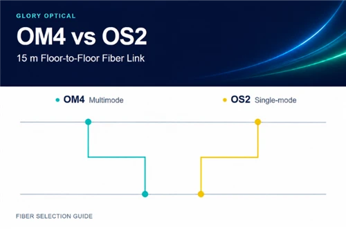
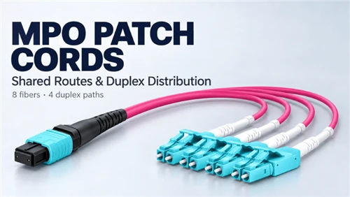
For a floor-to-floor switch link of about 15 m, the switch module decides the fiber type and the distance rarely matters. Multimode SR optics on OM4 and single-mode LR or BiDi optics on OS2 both reach far beyond 15 m. Read the module part number at both ends, choose the fiber that module is specified for, then confirm core count, cable construction, fire rating and patching before you compare quotes.
Key facts for this decision
- 10GBASE-SR supports up to 300 m on OM3 and 400 m on OM4; 10GBASE-LR supports 10 km on single-mode fiber (Cisco SFP+ data sheet).
- 15 m of OM4 at 3.0 dB/km adds about 0.05 dB. At this length, connection count and connector loss shape the loss budget.
- A duplex link uses 2 fibers; a single-fiber BiDi pair uses 1. Spare fibers in the same jacket share one physical route.
- A product labeled "patch cable" needs its datasheet checked for fire rating, armor, pulling tension and bend radius before it goes into a riser or conduit.
A 15 m floor-to-floor link: the scenario and the open questions
This guide follows an illustrative project, and it is not a Glory customer case. Two switches sit on different floors, the planned route is about 15 m, and the goal is more throughput between them. A supplier has quoted a four-fiber, micro-armored, OM4, pre-terminated assembly at roughly US$400, and the installer is considering LC keystone couplers for patching. The supplier links recent price increases to data center demand. That explanation comes from the supplier, and this guide does not treat it as market data.

Figure 1. The route in the example: two switch modules, two optional LC patching points and one floor penetration. Each added connection takes a share of the loss budget.
The table sorts what the project supplies from what still has to be collected. Anything in the middle column is a question for the supplier or the site survey.
| Item | Status | How this guide uses it |
|---|---|---|
| Route of about 15 m between floors | Stated, not yet measured | Re-measure along the real path and add slack at both ends |
| Goal of higher switch-to-switch throughput | Stated | Needs a target speed and the module part numbers |
| 4-fiber, micro-armored, OM4, pre-terminated cable at about US$400 | Quote received | Candidate option; price compared only after specs match |
| LC keystone patching | Idea under review | Checked for loss, fiber type and back-end protection |
| Switch models and installed modules | Unknown | First item to collect |
| Full cable datasheet, jacket marking, route conditions | Unknown | Required before fixed installation |
| Price increase attributed to data center demand | Supplier statement | Not used as evidence |
Start with the target speed and the module in each switch
A transceiver is built for one fiber type and one wavelength window. Cisco's published SFP+ data sheet shows how the same 10 Gigabit Ethernet speed maps to different cable choices depending on the module.
| Module (Cisco example) | Wavelength | Fiber it is specified for | Fibers per link | Specified reach |
|---|---|---|---|---|
| 10GBASE-SR (SFP-10G-SR) | 850 nm | Multimode: OM3 up to 300 m, OM4 up to 400 m | 2 (dual LC) | 400 m on OM4 |
| 10GBASE-LR (SFP-10G-LR) | 1310 nm | Single-mode (G.652) | 2 (dual LC) | 10 km |
| 10GBASE-BX10 BiDi (SFP-10G-BXD-I / BXU-I) | 1330 nm and 1270 nm | Single-mode, one strand | 1 | 10 km |
Three details from the same data sheet affect a short link. The minimum cabling distance for the -SR and -LR modules is 2 m, so 15 m sits comfortably inside the range. The listed connector is dual LC/PC, and Cisco states that only PC or UPC patch cords are supported, so a pre-terminated assembly for these modules should carry LC/UPC ends. A BiDi pair needs two different modules, one at each end, connected by a single strand.
Higher speeds tighten the loss allowance. Fluke Networks cites 1.5 dB maximum channel insertion loss for 40GBASE-SR4 over OM4, which makes the number of connections in the path a design question. A data center fiber cabling design guide covers the 400G and 800G cases for new rooms.
OM4 vs OS2: how to choose for this link
OM4 is a laser-optimized 50/125 µm multimode fiber used with 850 nm optics such as 10GBASE-SR. OS2 is a 9/125 µm single-mode fiber used with 1310 nm and 1550 nm optics such as 10GBASE-LR. At 15 m, both fibers carry the signal with large margin, so the decision rests on equipment and plans.
- Both switches already hold SR modules and the speed will stay put for the life of the cable. Choose OM4. The cable matches the modules in hand and the SR reach leaves wide headroom.
- The modules will be replaced anyway, or a later move to a higher speed is likely. Price OS2 together with LR or BiDi modules for both ends. The total bill of materials, including transceivers, is the comparison that counts.
- The plan is still open. Ask suppliers for a hybrid construction that carries both OM4 and OS2 fibers. The Fiber Optic Association notes that many users add single-mode fiber to multimode cables because the extra fibers cost little compared with pulling a second cable.
- OM3 is also an option. At 15 m, OM3 meets the 10GBASE-SR reach in Cisco's table. OM4 earns its premium on longer runs and on tight-budget higher-speed links.
Four fibers or six: count from the module first
Each duplex Ethernet link consumes two fibers, and each BiDi link consumes one. Count the fibers the chosen optics need today, then decide what the remainder is for.
| Cable | What it can carry | What to confirm |
|---|---|---|
| 4 fibers | One duplex link plus one spare pair, or two duplex links with no spare | Whether a second parallel link (for example a link aggregation group) is planned |
| 6 fibers | One duplex link plus two spare pairs, or up to three duplex links | Outer diameter, bend radius and connector head size, which can grow with fiber count |
| Hybrid (for example OM4 pair plus OS2 pair) | One multimode link and one single-mode link in a single jacket | Color coding and labels so each pair reaches the right module |
Spare fibers cover damage during termination and later changes. The Fiber Optic Association recommends adding spares during design, because fibers cost little next to installing another cable. A spare pair travels in the same jacket along the same path as the working pair. If the requirement is protection against a cut or fire in the riser, it calls for a second route with its own drawing, and extra fibers in one cable cannot supply it.
Can a "patch cable" go between floors? What to check before fixed installation
"Patch cable" names a product category: a factory-terminated assembly. It says little about whether that assembly is built for a riser, a conduit or a floor penetration. The Fiber Optic Association states that every cable installed indoors must meet fire codes, that unmarked cable should never be installed indoors, and that outdoor-rated cable without a fire rating is limited to short indoor lengths (50 feet in its US guidance). The checks below turn those points into questions for the datasheet.
| Check | Why it matters | Where to find it |
|---|---|---|
| Jacket fire marking | US premises cable carries OFN, OFNR (riser) or OFNP (plenum) style ratings under NEC Article 770; other regions use their own classes | Printed on the jacket and listed in the datasheet |
| Armor type | Metallic armor is conductive and must be grounded and bonded; non-metallic armor follows different rules | Cable construction drawing |
| Pulling tension and strength members | Pull on the strength members, never on the fiber or connector; patch-cord-class cable has a much lower tension limit than riser cable | Datasheet: installation tension (N) |
| Bend radius while pulling and at rest | Common rule: 20 times cable diameter under tension, 10 times once installed. A 3 mm cord gives 60 mm and 30 mm | Datasheet takes precedence over the rule |
| Connector head and boot size | The pre-terminated end must pass through the sleeve, hole or conduit without being forced | Dimensioned drawing from the supplier |
| Floor penetration | Indoor installations require firestopping where cable passes through floors | Local code and the building's firestop detail |
| Installation direction | Vertical runs are best dropped down with hangers and service loops rather than pulled up | Installer method statement |
Glory's own bend-limits guide lists indoor LC/SC patch cord installation tension at 60–150 N, compared with up to 1,200 N for an indoor riser cable, and tells installers to pull on the aramid strength members rather than the jacket. Apply the same logic to any pre-terminated assembly: obtain its tension rating and use a pulling sleeve or pulling eye if the supplier provides one. More figures are in How Flexible Is Fiber Optic Cable? Bend Limits, Tolerances & Real Numbers.
LC keystone patching and protecting the back-end fiber
An LC duplex keystone coupler snaps into a faceplate or keystone panel and joins two LC connectors. One published example, Eaton's N455-000-WH-KJ, is a multimode LC duplex coupler for 50/125 or 62.5/125 fiber, and its listing accepts either two simplex connectors or one duplex connector. A single-mode link needs a coupler specified for single-mode fiber, so check the fiber type on the listing.
Each coupler adds a mated connection
Fluke Networks explains that the TIA maximum of 0.75 dB per connector is a worst-case figure, while typical standard-loss connectors fall around 0.3 to 0.5 dB and low-loss ones around 0.15 to 0.2 dB. Here is illustrative arithmetic for the 15 m link against a 1.5 dB allowance:
| Loss component | Calculation | Result |
|---|---|---|
| 15 m of OM4 | 0.015 km × 3.0 dB/km | about 0.05 dB |
| Two couplers at 0.3 dB each (typical) | 2 × 0.3 dB | 0.6 dB |
| Total with typical values | about 0.65 dB, leaving about 0.85 dB | |
| Two couplers at the 0.75 dB worst case | 2 × 0.75 dB plus 0.05 dB | 1.55 dB, above 1.5 dB |
The 1.5 dB allowance in this example applies to 40GBASE-SR4-class links, and 10 Gigabit duplex links follow their own channel budgets. The principle carries over: at 15 m the fiber contributes almost nothing and connections consume the budget. Ask the supplier for the measured insertion loss of the coupler and the connectors, and keep the number of mated pairs to the minimum the maintenance plan needs.
Protect the point where fibers separate
If the assembly fans out into individual fibers behind the wall plate, that transition needs a supported, protected location. The Fiber Optic Association notes that distribution-style cable has fibers that are not individually reinforced, so it should be terminated inside a patch panel or junction box. Use a fiber termination box or a rack-side fiber optic patch panel to hold the breakout, the slack and the bend radius. Glory's fiber optic termination box range is one place to look for the enclosure. A bare keystone faceplate leaves the legs with no strain relief.
Compare quotes line by line
A US$400 quote becomes comparable only when the same items are in each offer. Use the list below as a request template.
| Line item | Specify |
|---|---|
| Fiber | Type and grade (OM4 or OS2, plus any hybrid layout), fiber count and color or label map |
| Connectors | LC, polish (UPC unless the module calls for another), duplex clip and polarity |
| Length | Measured route plus slack at each end, and where the supplier measures from |
| Cable construction | Jacket and fire rating, armor material, outer diameter, pulling provision |
| Test evidence | Insertion loss result for each fiber, with a report tied to the assembly |
| Accessories | Couplers, faceplates, termination box or panel, patch cords, labels |
| Services | Installation, firestopping, testing, warranty and delivery time |
Inspect, test and document the installed link
Fluke Networks advises that the only way to confirm the channel meets its insertion loss requirement is a Tier 1 test with an optical loss test set after installation. Inspect and clean every connector end before mating, test each fiber, and store the results with the route drawing. Re-test if construction work happens near the route later, because crush and microbend damage can show up weeks after the event.
Procurement confirmation checklist
- Current and target speed, plus the part number of each switch and module.
- Measured route length, slack at each end and the space for the pre-terminated connector head to pass.
- Fiber type, fiber count, connector type and polish, and polarity.
- Cable construction, jacket fire rating and the manufacturer's installation parameters.
- Patching interface, strain relief, protection for any fiber breakout and slack storage.
- What the quote includes, the test report supplied and the acceptance method.
Frequently asked questions
Q: Is OM4 or OS2 better for a 15 m link?
A: Both reach far beyond 15 m, so the better choice is the one that matches your switch modules and upgrade plan. OM4 suits existing SR modules, and OS2 suits LR or BiDi modules and longer-term flexibility. Compare the full bill of materials including transceivers.
Q: Can I use OS2 cable with a multimode SR module?
A: Use the fiber type the module is specified for. Cisco's data sheet lists the 10GBASE-SR module for multimode fiber and the 10GBASE-LR module for single-mode fiber. Confirm the part number before ordering the cable.
Q: How far can OM4 carry 10 Gigabit Ethernet?
A: Cisco's data sheet gives up to 400 m for 10GBASE-SR on OM4 and up to 300 m on OM3.
Q: Do I need six fibers instead of four?
A: Count the fibers your optics need now. Four fibers hold one duplex link and a spare pair; six hold a link and two spare pairs. Choose six if you expect a second link or want a larger reserve, and check the larger outer diameter against your pathway.
Q: Do spare fibers give me redundancy?
A: They protect against a damaged fiber inside the cable. A cut or fire along the route affects every fiber in the jacket, so route redundancy needs a second cable on a separate path.
Q: Can a micro-armored patch cable be installed in a riser between floors?
A: That depends on its jacket marking, fire rating and installation specification. Check the printed rating and the datasheet for riser or plenum suitability, the armor type and the pulling tension, and follow local code and firestop requirements.
Q: Does an LC keystone coupler add loss?
A: Yes. Each coupler creates one mated connection. Use the supplier's measured insertion loss in your budget and keep the number of connections to what the maintenance plan requires.
Get a quote that matches your route
Send the route length, the switch and module part numbers, the fiber type and the fire-rating requirement. Glory Optical lists built-to-length LC duplex assemblies in its fiber optic cable assemblies range and offers OEM/ODM options for custom constructions.
Request a Quote Contact the engineering teamSources
- Cisco, Cisco 10GBASE SFP+ Modules Data Sheet (SR, LR and BiDi reach, connector note, minimum distance).
- Fiber Optic Association, Fiber Optic Cables (cable construction, fire ratings, armored cable grounding, bend radius, spare fibers).
- Fiber Optic Association, Fiber Optic Installation (premises installation, vertical runs, firestopping, hybrid cable).
- Fluke Networks, Cable Testing 101: But the Standard Says 0.75 dB! (connector loss, channel budget, Tier 1 testing).
- Eaton, N455-000-WH-KJ duplex multimode LC keystone coupler (example product listing).
- TIA, ANSI/TIA-568.3-E Optical Fiber Cabling and Components Standard (premises optical fiber cabling and components).
- Glory Optical, How Flexible Is Fiber Optic Cable? Bend Limits, Tolerances & Real Numbers (2026).