An operator planning to introduce 25GS-PON rarely starts with an empty network. The fiber, PLC splitters, splice closures and distribution boxes may already be carrying GPON or XGS-PON services. Reusing this passive infrastructure can reduce construction work, but only when the complete optical path still fits the new system. A splitter with higher-than-expected loss, an additional connector pair or a coexistence component can consume the remaining margin and affect subscribers at the end of the route.
Why the Traditional Upgrade Approach Has Limits
A common upgrade method is to add or replace OLT equipment while leaving the ODN unchanged. This can work because several PON generations may share passive infrastructure under an approved wavelength plan. Glory Optical's guide to PON coexistence and the wavelength window explains the basic relationship between GPON, XGS-PON and Combo-PON.
The limitation is that "same fiber" does not mean "same available margin." Long cable routes, two-stage splitting, repair splices, connector pairs and coexistence components all use part of the optical budget. If an existing link is already close to its limit, a network diagram may look compatible while the most distant ONU has too little margin.
The traditional choices are to reduce the split ratio, shorten the route, replace part of the ODN or use a higher optical class. Version 4 of the 25GS-PON specification makes the last option easier to understand by defining B+, C+ and Class D choices for MPM applications.
B+, C+ and Class D at a Glance
| Optical Class | Maximum Optical Path Loss | Practical Position | Main Planning Question |
|---|---|---|---|
| B+ | 28 dB | Standard-budget ODN | Can the existing passive network be reused without major changes? |
| C+ | 32 dB | Intermediate option | Does the route need more margin without moving directly to the highest class? |
| Class D | 35 dB | High-loss ODN | Is additional budget required for more splitting, distance or passive connection points? |
C+ is the middle option between B+ and Class D. It was already present in earlier 25GS-PON work; V4 places it within the dedicated MPM optical specifications and adds B+ and Class D around it. The official source is the 25GS-PON Specification V4.0.
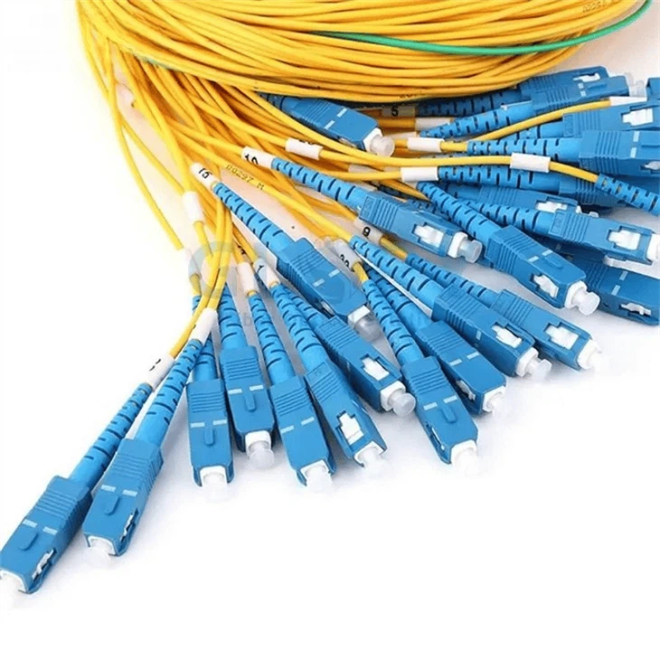
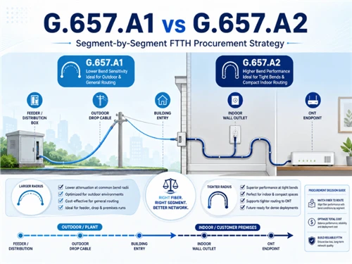
Glory Optical 1×32 ABS-box PLC splitter. The published product configuration uses G.657A1 fiber and SC/APC interfaces; the final splitter loss and connector plan should be included in the project ODN calculation.
1. Reuse More of the Existing ODN with B+
Many GPON networks were planned around a familiar 28 dB B+ ceiling. Adding a B+ option to the 25GS-PON MPM specifications gives operators a clearer starting point for checking whether an installed route can remain in service.
Consider a network with a moderate split ratio, short-to-medium cable distance and only a few connector pairs. If its measured loss remains comfortably inside the supported range, the feeder cable, splitter, closures and distribution boxes may not need to be rebuilt.
Check the furthest path
Use the route with the highest measured loss rather than relying on the average ONU result.
Check splitter variation
Review the worst output port and uniformity, not only the nominal or average insertion loss.
Check field changes
Count repair splices, replacement patch cords and any new distribution points added after installation.
Check connector interfaces
Confirm that APC and UPC are not mixed and that the end faces remain clean and undamaged.
B+ creates a practical reuse path. The field audit decides whether that path is actually available.
2. Use C+ or Class D When the Route Needs More Room
Not every ODN fits comfortably inside 28 dB. The extra loss may come from distance, but it may also come from a larger splitter, two-stage splitting or several connectorized distribution points.
C+ raises the maximum budget to 32 dB and provides an intermediate choice. Class D extends it to 35 dB. The additional room may be assigned to:
- a higher split ratio;
- more fiber distance;
- additional connector or splice points;
- a two-stage splitter design; or
- more allowance for maintenance and ageing.
It cannot be assigned to all of these at the same time. Moving from a 1:32 to a 1:64 splitter already consumes several additional decibels before cable, connector and splice losses are added. The worked example in 1:32 vs 1:64 PLC Splitter shows why the split ratio must be evaluated as part of the complete route.
The simple conclusion is to buy enough optical headroom for the planned ODN, not the biggest number without a calculation.
3. Upgrade Subscribers Gradually with Combo-PON
A complete network migration rarely happens in one day. Residential users may remain on GPON, other subscribers may move to XGS-PON, and selected business or mobile-transport connections may need 25GS-PON first.
Combo-PON modules support a staged migration by allowing different PON generations to share passive infrastructure under a compatible wavelength plan. Instead of replacing every ONU at once, the operator can move services according to demand.
- Measure the existing ODN and record its remaining loss margin.
- Confirm which PON generations must coexist.
- Select the appropriate B+, C+ or Class D interface.
- Upgrade priority subscribers while legacy services remain active.
- Continue the migration as service demand grows.
The value is operational flexibility: the passive network can support a controlled transition instead of forcing a single large replacement project.
Match Passive Components to the Selected Budget
The active OLT and ONU optics define the supported optical class. The passive components between them decide how much of that budget is left when the signal reaches the customer.
| Passive Component | What to Confirm | Why It Matters |
|---|---|---|
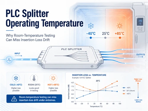
| PLC splitter | Ratio, maximum insertion loss, uniformity, return loss, wavelength range and package | The worst output port can determine whether the most distant ONU has enough margin. |
| WDM or coexistence component | Insertion loss, isolation and supported wavelength plan | A coexistence design can consume part of the available loss allowance. |
| Adapter and connector pair | Interface, polish, mated-pair loss, return loss and end-face condition | Incorrect or contaminated connections add loss and reflection. |
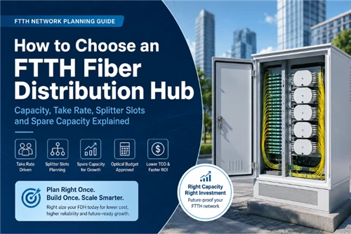
| Fiber distribution box | Splitter format, adapter field, splice capacity, port map and cable entries | The loaded enclosure must match the optical BOM as well as the mechanical layout. |
| Splice closure and cable | Splice quantity, cable distance, fiber type, routing and reserve plan | Every splice and kilometer contributes to the final end-to-end loss. |
Connector interfaces should remain consistent throughout the route. APC and UPC should not be directly mated; see APC vs UPC Fiber Connectors for the practical difference.
For loaded enclosures, specify the splitter, adapters, pigtails, splice capacity and cable-entry arrangement as one configuration. The FTTH Fiber Distribution Box RFQ Guide lists the information needed to compare quotations on the same basis.
Glory Optical Product Options for Passive ODN Nodes
The following products do not define the B+, C+ or Class D rating-the approved OLT and ONU optics do that. Their role is to control splitting, connection, routing and distribution so the passive path can be built to the selected project budget.
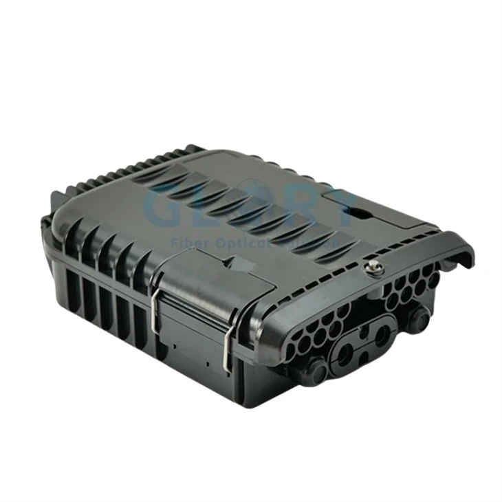

Build the Passive ODN as One Matched BOM
Send Glory Optical the target optical class, split ratio, route distance, connector and splice count, coexistence plan, enclosure position and required test records. The team can match PLC splitter format, distribution box, adapters, pigtails, closures and fiber cable to the approved ODN layout.
Request a Project Quote View PLC Splitters View the ODN Solution GuideFrequently Asked Questions
Q: What changed in the 25GS-PON V4 optical budget?
A: V4 adds B+ and Class D options for Multi-PON Module or Combo-PON applications, places C+ within dedicated MPM specifications and completes additional high-loss 25G upstream requirements.
Q: What is the difference between B+, C+ and Class D?
A: Their maximum optical path losses are 28 dB, 32 dB and 35 dB respectively. B+ suits standard-budget routes, C+ provides an intermediate option, and Class D provides the largest of these three loss allowances.
Q: Does Class D automatically support a 1:128 split?
A: No. Splitter loss is only one part of the total ODN loss. Fiber, connectors, splices, coexistence components and engineering margin must also fit within the selected optical budget.
Q: Can an existing GPON or XGS-PON ODN carry 25GS-PON?
A: It may be possible to reuse the passive fiber and splitters, but the actual route loss, wavelength plan, component performance and OLT and ONU compatibility must be verified before migration.
Q: What is C+ in 25GS-PON?
A: C+ is the intermediate MPM optical-budget class with a maximum optical path loss of 32 dB. It sits between the 28 dB B+ class and the 35 dB Class D option.
Q: What information is needed to select passive components?
A: Provide the optical class, split ratio, route distance, splitter stages, connector and splice count, coexistence plan, enclosure type and required test documentation.
Conclusion
25GS-PON V4 gives operators three understandable MPM budget choices. B+ supports standard-budget routes, C+ fills the middle position, and Class D provides more room for demanding ODNs. The benefit is greater flexibility-not permission to ignore splitter, connector, fiber and coexistence losses.
Start with the measured path, select the optical class that fits it, and then build the passive BOM around that calculation. When the PLC splitter, adapters, enclosure layout, splices and cable route are reviewed together, an upgrade becomes much easier to plan and verify.
Technical source: 25GS-PON Specification V4.0, dated March 13, 2026. Product data is model-specific; confirm the latest drawings, optical reports and ordered configuration before procurement.