1. FTTH Network Design Is More Than Bringing Fiber to a Home
FTTH deployment is not only about connecting homes with optical fiber. For ISPs, contractors and OEM buyers, the passive optical distribution network determines the project's loss budget, splitter flexibility, installation cost, maintenance complexity and future upgrade path. A route that looks simple on a map can become expensive if the split ratio is too aggressive, the box capacity is underspecified, the drop cable path is not controlled or the handoff package does not record what was actually installed.
This guide focuses on the engineering and procurement layer behind an FTTH rollout: ODN architecture, feeder/distribution/drop/subscriber layers, centralized and distributed splitter placement, GPON and XGS-PON loss-budget planning, BOM preparation, fiber distribution box and NAP selection, field testing and documentation. It is intended to support a coordinated ODN Fiber Optic Solution for FTTH Networks, not a loose catalog of passive parts.
Design principle: build the FTTH ODN around the worst-case subscriber path, not the average path. The longest route, highest splitter loss, most connector pairs and most difficult drop path decide whether the network is robust.

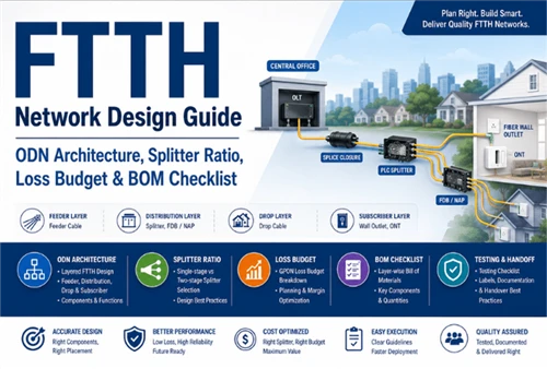
2. FTTH ODN Architecture: From OLT to ONT
The ODN is the passive fiber path between the optical line terminal and the customer ONT. FOA describes FTTH design as project-specific rather than formulaic because density, geography, construction method and future upgrade assumptions change the architecture from one network to another. Most FTTH access networks use PON architecture because it reduces active field equipment, but the physical ODN still requires careful component-level design.
A practical ODN drawing should show four layers. The feeder layer carries high-fiber-count cable from the central office, headend or remote OLT area to a primary splice point or cabinet. The distribution layer places splitters and routes fibers toward neighborhoods, buildings or access terminals. The drop layer connects the terminal to the subscriber. The subscriber layer terminates the fiber at the NID, wall outlet or ONT area and provides the final patch connection.
| Layer | Main Function | Typical Components | Glory Optics Product Fit | Design Notes |
|---|---|---|---|---|
| Feeder layer | Carry fibers from OLT/CO to the first distribution point. | Outdoor feeder cable, ODF, splice closure, route labels. | Outdoor fiber cable; fiber joint enclosure / splice closure. | Plan route length, spare fibers, splice access and restoration space. |
| Distribution layer | Split and distribute feeder capacity to service areas. | PLC splitter, splitter tray, distribution cable, FDB/FAT/NAP. | PLC splitter; fiber box range; fiber termination / distribution box. | Splitter ratio and box capacity drive loss budget and maintenance access. |
| Drop layer | Connect each subscriber from NAP/FDB to building entry. | FTTH drop cable, clamp, fast connector or splice point. | FTTH drop cable; fast connectors; drop accessories. | Control bend radius, strain relief, pulling route and connector protection. |
| Subscriber layer | Terminate the fiber and present the customer interface. | NID, fiber wall outlet, adapter, pigtail, patch cord, ONT. | fiber wall outlet; SC/APC pigtail; adapter; patch cord. | Use consistent APC/UPC policy and label the demarcation point clearly. |
| Testing and documentation | Verify that the installed ODN matches the design. | Inspection scope, cleaning kit, OLTS/power meter, OTDR, labels, port map. | tool kit and cleaning accessories; batch labeling support. | Record expected vs measured levels at handoff and keep as-built data. |
3. Centralized vs Distributed Splitter Architecture
Splitter placement is one of the first ODN architecture decisions. The Fiber Broadband Association's 2025 splitter architecture guide defines centralized architectures as designs where splitters sit in a central office or FDH, while distributed architectures place splitters closer to customers, pedestals or closures. FOA similarly separates centralized and cascaded approaches and notes that one or two splitting levels are normally recommended for maintainability.
Centralized splitting often simplifies splitter access, port assignment, testing and future reconfiguration. It can be attractive where cabinets can be placed, feeder fiber is available and operators want a clean cross-connect model. The trade-off is that it usually needs higher fiber count distribution cables and a larger FDH footprint.
Distributed or cascaded splitting moves some splitting closer to subscribers. This can reduce distribution fiber count and support success-based deployment, where splitters are added as subscribers are connected. Corning highlights success-based splitter deployment as a way to defer splitter cost and improve OLT port utilization. The trade-off is more field nodes, more documentation discipline and more care during OTDR interpretation.

Open Fiber's published progress data shows why density changes ODN decisions: in Italy it reports more than 167,000 km of infrastructure and 17.36 million FTTH property units, with denser Black Areas averaging one property unit per 4.5 m of network and White Areas averaging one per 15.8 m. That difference is not just civil-work cost; it changes feeder sizing, splitter placement, drop length, terminal spacing and maintenance logistics.
4. Splitter Ratio Planning: 1x16, 1x32 or 1x64?
The splitter ratio balances OLT port efficiency against optical margin and operational flexibility. A higher split ratio lowers active port cost per subscriber, but it consumes more optical budget and leaves less margin for long routes, extra connector pairs, dirty ports, repair splices and future rearrangements. FOA notes that GPON commonly uses 32 or 64 as practical split ratios, while XG(S)-PON can support higher maximum ratios depending on standard, distance and scenario; in procurement, however, the correct answer is still the one that survives the worst-case path.
| Split Ratio | Typical Use Case | Loss Impact | Fiber Count Impact | Suitable Scenario | Notes |
|---|---|---|---|---|---|
| 1x8 | Small buildings, low-density areas, second-stage split. | Low to moderate splitter loss. | More feeder or distribution fibers per subscriber. | Longer routes, high margin requirements, small MDUs. | Useful when the design must protect optical headroom. |
| 1x16 | Suburban areas, compact MDUs, conservative GPON design. | Moderate loss. | Moderate fiber count. | Routes with uncertain length or multiple connector points. | Often a safer choice when field conditions are less controlled. |
| 1x32 | Mainstream residential GPON ODN. | High but commonly manageable within Class B+/C+ budgets. | Efficient OLT and feeder utilization. | Balanced SFU deployments and many standard FTTH rollouts. | Check connector count and route length before treating it as default. |
| 1x64 | Dense urban or short-reach networks with sufficient budget. | Very high splitter loss. | Highly efficient feeder and OLT utilization. | Short routes, higher optical class, tight documentation control. | Do not use as a cost shortcut if it removes all field margin. |
| 1x4 + 1x8 two-stage split | Cascaded 32-way design. | Similar total split count to 1x32, with added stage complexity. | Lower distribution fiber count after the first split. | MDU, rural, pedestal or NAP-based architecture. | Design to the worst second-stage path and label ports carefully. |
A recent FTTH design discussion on LinkedIn warns against confusing the hardware power budget with the ODN link-loss budget. One planner framed the ODN as the passive part that only subtracts power - splitters, fiber, connectors and splices - and warned that a 1x64 design can consume margin faster than junior planners expect. Treat this as a useful practitioner signal, not a standards reference.
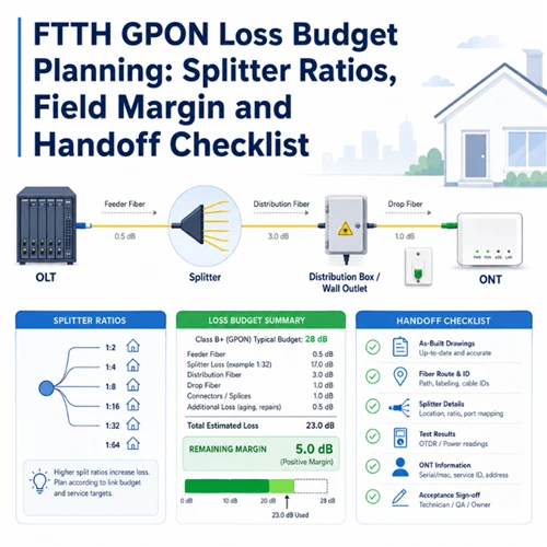
5. FTTH Loss Budget Planning
An FTTH loss budget estimates whether the installed ODN will keep the ONT receive power inside the equipment window. FOA separates power budget from loss budget: the power budget belongs to the electronics, while the loss budget is the estimated installed cable-plant loss. The same loss budget should be used twice - first during design to decide whether the link should work, and again after installation to compare measured results against the expected value.
Total ODN Loss = Fiber Attenuation + PLC Splitter Insertion Loss + Connector-Pair Loss + Splice Loss + Engineering Margin
For GPON, many projects still plan around ITU-T G.984.2 optical classes such as Class B+ or C+. For XGS-PON coexistence or migration, ITU-T G.9807.1 budgets and return-loss requirements should be checked during design rather than after civil work is finished. Dell'Oro's 2026 broadband forecast expects PON equipment revenue growth from 2025 to 2030 to be driven largely by XGS-PON deployments in North America, EMEA and CALA, which makes XGS-PON-ready ODN margin a commercial planning issue, not only a technical topic. Nokia's Converge ICT deployment note is a useful public example of a GPON FTTH build using platforms positioned for 10G PON and beyond.
| Loss Source | Planning Item | Typical Consideration | Why It Matters |
|---|---|---|---|
| Fiber attenuation | Route distance and wavelength. | Use the project fiber type and route length; upstream 1310 nm can be the conservative case. | Longer feeder and rural drops can consume margin even before splitting. |
| PLC splitter loss | Selected ratio and package type. | 1x32 and 1x64 are the major passive-loss decisions; use datasheet insertion loss. | The splitter is usually the largest single passive loss element in a PON ODN. |
| Connector pair loss | Every mated pair from OLT/ODF to ONT patch cord. | Count ODF, cabinet, splitter input/output, FDB/NAP, wall outlet and ONT interface. | Two forgotten connector pairs can remove more margin than several kilometers of fiber. |
| Splice loss | Feeder, distribution and drop splice count. | Fusion splices are small individually but add up in restoration-heavy routes. | Future repair splices need margin, not just initial commissioning values. |
| Engineering margin | Reserved buffer. | Commonly planned around 2–3 dB depending on operator policy. | Protects against aging, contamination, measurement uncertainty and route changes. |

For a deeper article dedicated only to loss math and handoff records, link this section to FTTH GPON Loss Budget Planning. This page should stay broader: the loss budget is one part of an ODN design, and it must be connected to splitter architecture, BOM and field testing.
6. FTTH BOM Checklist by Network Layer
A strong FTTH BOM is not just a purchasing list. It is a project-control document that ties network architecture to component quantities, connector policy, packaging, labels and test evidence. Build the BOM in the same layers as the ODN design so procurement teams can see what each component does and field teams can install it without guessing.
| Network Segment | Required Components | Optional Components | Buyer Should Confirm |
|---|---|---|---|
| Feeder | Outdoor feeder cable, splice closure, ODF patching, labels. | Armored cable, aerial hardware, duct markers, reserve loops. | Fiber count, route length, cable construction, installation method and spare capacity. |
| Distribution | PLC splitter, distribution cable, FDB/FAT/NAP, splice trays. | Splitter cassette, LGX module, pre-connectorized terminal, pole bracket. | Split ratio, port count, IP rating, mounting method, adapter type and labeling layout. |
| Drop | FTTH drop cable, clamps, cable ties, splice protection or connector. | Pre-terminated drop, fast connector, pulling grip, customer-side NID. | Drop length range, bend radius, indoor/outdoor route, connector protection and MOQ. |
| Subscriber | Fiber wall outlet, SC/APC adapter, pigtail, patch cord to ONT. | Logo printing, neutral faceplate, shuttered adapter, wall labels. | APC/UPC policy, wall-mount space, local installation practice and demarcation ownership. |
| Testing | End-face inspection, OLTS or power-meter record, OTDR report, port map. | Batch test report, QR label, as-built template, cleaning kit. | Acceptance threshold, report format, label format, language and project handoff package. |
| Packaging and labeling | Individual bags, carton label, port labels, batch number. | Neutral packaging, OEM logo, kitting by site, pallet label. | Carton quantity, installation-site grouping, language, barcode/QR and traceability requirements. |

7. How to Choose Fiber Distribution Boxes and NAP Boxes
The distribution box or NAP is where network design becomes field behavior. A good box does more than hold adapters. It must protect bend radius, separate feeder and drop management, leave room for splicing, identify ports clearly and allow technicians to work without disturbing live fibers. A poor box selection may pass initial cost review but create failures during subscriber activation and maintenance.
For outdoor FTTH, define the box by role, not only by port number. A fiber distribution box may terminate feeder cable, hold a 1x8, 1x16 or 1x32 splitter and present drop ports. A NAP box often serves as a field access point for multiple subscriber drops, with integrated adapters and sometimes a PLC splitter. A fiber termination box vs distribution box comparison helps avoid confusion in procurement language, because FTB, FDB, FAT and NAP are often used differently by region.
Check six details before ordering: port count, splitter capacity, splice tray capacity, cable entry and strain relief, IP rating, and label layout. If the project expects future XGS-PON overlay or subscriber churn, add spare ports and a cleaner port-map design rather than filling every adapter on day one.

A public r/FiberOptics discussion about a "messy case" described residential PON splitters taped to the top of a tray, multiple buffer tubes crowded into one enclosure and service disturbance during discovery work. The lesson for a procurement article is clear: box capacity, tray layout and fiber management space are E-E-A-T details. They directly affect troubleshooting time and service continuity.
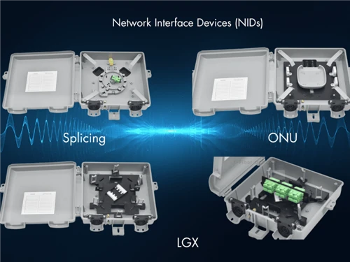
8. Field Installation Choices: Splicing vs Pre-Terminated Drop
Drop installation strategy affects labor, inventory and loss-budget control. Field splicing is flexible: the crew can cut the cable to exact route length, work around unexpected building entry points and repair damaged drops without replacing the whole assembly. It is also dependent on splicer quality, technician skill, splice protection and the available working space inside the wall outlet or NAP.
Pre-terminated drop cable can speed repetitive deployments, reduce field splicing and improve consistency when route length is predictable. It is useful for apartment buildings, campus-style housing and standardized SFU builds. The risk is excess slack, connector damage during pulling and inventory complexity if too many lengths are required. For projects using pre-terminated drops, specify dust caps, pulling protection, individual packaging and port-label matching.
| Option | Advantages | Limitations | Best Used For | Procurement Notes |
|---|---|---|---|---|
| Field splicing | Flexible length, good for uncertain routes, repair-friendly. | Requires trained technicians, splice tools, clean work practice and time. | Rural drops, irregular buildings, repairs, custom routes. | Buy pigtails, splice sleeves, wall outlets and cleaning tools together. |
| Pre-terminated drop | Fast activation, fewer field splices, consistent connector quality. | Length planning, connector protection and slack management are critical. | MDU, standardized SFU, high-volume installations. | Specify connector type, length range, pulling eye, caps, labels and packaging. |
9. Testing and Handoff Checklist
Testing turns an FTTH design into a verified asset. The basic sequence is inspect, clean, measure and document. IEC 61300-3-35 provides visual inspection criteria for connector end faces and explicitly states that visual inspection does not replace optical performance measurement. VIAVI also emphasizes that contaminated or dirty fiber is a leading cause of optical network degradation and that both sides of a connection should be inspected to prevent cross-contamination.
At minimum, the handoff package should include end-face inspection where required, OLTS or optical power-meter records, OTDR traces for route and event documentation, splitter input/output levels, port maps, labels, as-built drawings, batch test reports and an expected-versus-measured loss table. This is especially important where multiple contractors work on feeder, distribution and drop segments separately.
Connector hygiene is part of the BOM. Include fiber optic tool kit, clean caps, inspection scope access and documented cleaning steps. The practical procedure can be internally linked to the fiber optic connector cleaning guide and the fiber optic pigtail guide.
10. FTTH RFQ Checklist for OEM and Project Supply
An effective RFQ should make the design assumptions visible. Instead of asking only for "1x32 splitter, 16-port box and drop cable," provide the information needed to build a coordinated ODN BOM.
11. FAQ: FTTH Network Design, ODN and BOM
-
Q: What is FTTH network design?
A: FTTH network design is the planning of the optical path from the OLT to the customer ONT. For the passive ODN, it includes route distance, feeder cable, distribution cable, splitter placement, split ratio, FDB/NAP capacity, drop cable route, wall outlet, connector and splice counts, loss budget, test method and handoff records.
Q: What is ODN in FTTH?
A: ODN means Optical Distribution Network. In FTTH, it is the passive fiber infrastructure between OLT and ONT: feeder cable, splice closure, PLC splitter, distribution cable, fiber distribution box or NAP, drop cable, NID or wall outlet, adapter, pigtail and patch cord.
Q: What components are needed in an FTTH network?
A: A practical FTTH project normally needs outdoor feeder cable, splice closures, PLC splitters, distribution cable, FDB/FAT/NAP boxes, FTTH drop cable, wall outlets, SC/APC pigtails, adapters, patch cords, labels, cleaning tools, test records and packaging traceability.
Q: What is the best splitter ratio for FTTH?
A: There is no universal best ratio. 1x32 is common in GPON residential networks, 1x16 keeps more margin for longer or uncertain routes, and 1x64 should only be used where distance, connector count, optical class and operational policy support it.
Q: How do you calculate FTTH loss budget?
A: Add fiber attenuation, PLC splitter insertion loss, connector-pair loss, splice loss and engineering margin. Compare the result with the OLT/ONT optical budget, then validate the installed path with power measurement and OTDR documentation where required.
Q: What is the difference between centralized and distributed splitting?
A: Centralized splitting places splitters in a central office, FDH or cabinet. Distributed splitting places splitters closer to subscribers in closures, pedestals, FDBs or NAPs. Centralized splitting can simplify management; distributed splitting can reduce distribution fiber count but increases field-node documentation requirements.
Q: What is the difference between a fiber distribution box and a NAP box?
A: A fiber distribution box distributes feeder fibers to multiple drop outputs and may contain a splitter. A NAP box is a network access point near subscribers, often with adapter ports and sometimes integrated splitting. In RFQs, specify function, port count, splitter capacity, mounting method and IP rating rather than relying on the name alone.
Q: What is the difference between ONT, NID and fiber wall outlet?
A: The ONT is active customer equipment. The NID is a demarcation enclosure at the building boundary or exterior wall. The fiber wall outlet is an indoor passive termination point that protects the final fiber and presents an adapter or pigtail connection for the ONT patch cord.
Q: Is pre-terminated drop cable better than field splicing?
A: Pre-terminated drop cable is faster where route lengths are standardized and connector protection is controlled. Field splicing is better where routes are uncertain, buildings vary or repairs are common. Many projects use both methods by area type.
Q: What tests are required before FTTH handoff?
A: Use connector end-face inspection where required, clean before mating, record optical power or OLTS results, capture OTDR traces for route/event documentation, verify splitter input/output levels, complete port maps, label terminals and deliver as-built drawings and expected-versus-measured loss tables.
Standards, Public Sources and Further Reading
- FOA: Fiber To The Home Network Design - project-specific FTTH design principles and architecture options.
- FOA: Optical Splitters - splitter levels, location and PON design considerations.
- FOA: Calculating Fiber Optic Loss Budgets - power budget vs loss budget, link-loss calculation and conservative planning.
- Fiber Broadband Association: PON Splitter Architectures - centralized, distributed and split-ratio terminology.
- FTTH Council Europe: FTTH Market Forecasts 2024–2030 - market growth context for full-fiber deployment.
- Dell'Oro Group Broadband Forecast - PON and XGS-PON market direction.
- Open Fiber Work Progress - real public deployment scale and density context.
- Nokia and Converge ICT FTTH Deployment - GPON deployment and 10G PON upgrade-ready platform example.
- Corning: Choosing the Right FTTH Network Architecture - success-based splitter deployment and architecture considerations.
- IEC 61300-3-35:2022 - visual inspection of fiber-optic connector end faces.
- VIAVI: What Is Fiber Inspection? - connector contamination, inspection and cleaning workflow.
- LinkedIn practitioner discussion - field signal on power budget vs link-loss budget confusion.
- Reddit r/FiberOptics discussion - public technician discussion illustrating box layout, tray capacity and maintainability issues.
Social-media and forum references are used only as field-observation signals. Standards, association guidance, operator information and vendor technical resources should remain the basis for final engineering decisions. Loss values in this article are planning references; replace them with the selected datasheet and project specification before release to construction.
Reviewed by Glory Optics technical team for FTTH ODN component matching, splitter planning and project BOM support.
About Glory Optical: Ningbo Glory Optical Communication Co., Ltd. supplies FTTH / FTTx passive optical components including PLC splitters, fiber distribution and termination boxes, NAP boxes, splice closures, FTTH drop cable, fiber wall outlets, pigtails, adapters, patch cords and OEM/ODM project packaging. Send your topology, split ratio, subscriber count and documentation requirement for matched ODN BOM support.