The short answer
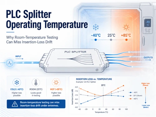
A PLC splitter datasheet may state an operating temperature such as −40°C to +85°C. That field defines an approved service range only when it is tied to the exact ordered package; it does not promise identical insertion loss at every temperature.
A published online-monitoring study reported maximum insertion-loss changes of 0.472 dB at 75°C and 0.486 dB at −40°C for its tested silica-based PLC splitter devices. These figures describe that study, not a universal PLC splitter acceptance limit.
Outdoor acceptance should combine room-temperature shipment data, environment-matched qualification evidence and optical measurements taken while the device is hot or cold.
1. Operating Range and Temperature Stability Answer Different Questions
Operating temperature defines the approved service range for a stated product configuration. Temperature stability, often expressed as maximum ΔIL, states how far insertion loss is allowed to move over a specified measurement range. Storage temperature applies when the product is not operating, while temperature cycling describes a qualification procedure rather than a field rating.
| Datasheet field | What it controls | Required clarification |
|---|---|---|
| Operating temperature | Approved field service | Exact package, connectorization, installation condition and duration |
| Storage temperature | Non-operating exposure | Packaging, recovery conditions and permitted duration |
| Temperature stability / ΔIL | Maximum optical movement over a stated span | Reference value, wavelength, monitored ports, sample size and method |
| Temperature-cycling qualification | Compliance with a defined environmental procedure | Standard, edition, category, cycle profile and whether IL was monitored during exposure |
Why a test range may be wider than the operating range
Glory's PLC splitter product family currently lists a 0.5 dB temperature-stability value over −40°C to +85°C and operating and storage ranges of −25°C to +70°C. Those fields should not be merged. A wider ΔIL measurement span can be used as a test or qualification envelope without extending the approved continuous-service range.
Shipment acceptance still requires the other optical fields described in Glory's PLC splitter test-report guide, including per-port insertion loss, uniformity, PDL, return loss, wavelength and connector inclusion.
2. What Online Temperature Monitoring Shows-and What It Does Not
The study Novel Research on Reliability of Silica-Based PLC Optical Splitters measured optical performance during temperature exposure rather than relying only on room-temperature measurements before and after the cycle.
| Test point | Maximum reported IL change | Use in this article |
|---|---|---|
| 75°C | 0.472 dB | Evidence that hot-state IL can differ from room-temperature IL |
| −40°C | 0.486 dB | Evidence that cold-state IL can differ from room-temperature IL |
The paper linked the measured behavior mainly to thermally induced movement at the PLC chip-to-fiber-array coupling interface. It also reported a clearer relationship between temperature and insertion loss than between temperature and PDL.
Supported conclusion
- Operating-state IL can differ from the room-temperature value.
- The change can reduce after temperature recovery.
- Package and coupling construction can influence the result.
Limits before procurement use
- Do not convert the study result into a universal 0.5 dB limit.
- Verify split ratio, package, wavelength, sample count and cycle profile in the full report.
- Request per-port and sample-to-sample data for the ordered product.
The practical value comes from measuring at the hot and cold states. A device can pass at room temperature before exposure, show temporary additional loss during exposure and pass again after recovery.
3. Package-Level Thermal Behavior Matters
A commercial PLC splitter includes more than the planar waveguide chip. Fiber arrays, V-groove substrates, adhesives, tubes, housings, pigtails, connectors, strain relief and cassette hardware can respond differently as temperature changes.
Engineering rule
Qualification evidence should follow the shipped package. A non-connectorized module report does not automatically approve an ABS box, plug-in cassette or splitter integrated into an outdoor terminal.
| Delivered format | Additional thermal variables | Evidence boundary |
|---|---|---|
| Blockless / mini-module | Tube, adhesive, bare-fiber routing and enclosure integration | Module qualification plus the loaded-box routing review |
| ABS box | Housing, jacketed pigtails, strain relief and connectors | Complete assembly data with connector inclusion stated |
| Cassette / LGX | Adapters, mounting frame, internal bends and interfaces | Connectorized cassette evidence, not chip-only evidence |
| Ribbon / high count | More output fibers, routing points and worst-port variation | Per-port data and worst-port temperature results |
| Outdoor loaded terminal | Enclosure solar load, internal temperature, adapters and cable routing | Splitter evidence plus loaded-enclosure thermal review |
Glory's splitter packaging and selection guide explains how blockless, ABS, cassette and rack-mount forms change installation and connectorization.
4. Show the Optical-Budget Inputs Before Applying ΔIL
Temperature-dependent loss matters in proportion to the remaining path margin. The examples below expose every planning input so the result can be checked. They are illustrative values, not PON class limits or Glory product specifications.
| Planning input | Case A: 28.0 dB budget | Case B: 32.0 dB budget |
|---|---|---|
| Splitter and passive branching loss | 17.0 dB | 20.5 dB |
| Fiber attenuation | 2.8 dB | 4.0 dB |
| Connector pairs | 1.6 dB | 2.0 dB |
| Splices | 0.6 dB | 0.8 dB |
| Other passive / coexistence elements | 1.0 dB | 1.5 dB |
| Ageing, repair and measurement reserve | 1.8 dB | 2.0 dB |
| Base planned path loss | 24.8 dB | 30.8 dB |
Case A: comfortable residual margin
Pre-temperature margin: 28.0 − 24.8 = 3.2 dB
After 0.5 dB temperature-drift allowance: 2.7 dB remains.
The thermal allowance consumes 15.6% of the original 3.2 dB margin.
Case B: tight residual margin
Pre-temperature margin: 32.0 − 30.8 = 1.2 dB
After 0.5 dB temperature-drift allowance: 0.7 dB remains.
The thermal allowance consumes 41.7% of the original 1.2 dB margin.
The 0.5 dB value is labeled as a temperature-drift allowance. Receiver sensitivity remains the system endpoint; ΔIL is an additional passive-path loss allowance that should remain separate from connector, ageing, repair and measurement reserves.
Temperature-dependent loss deserves closer review in paths with high split ratios, cascaded splitters, long routes, several connector pairs or legacy repairs. Glory's 1×32 versus 1×64 PLC splitter guide and 1:128 GPON analysis show why a physical splitter option does not approve the complete path.
5. The Room-Temperature Blind Spot
A room-temperature shipment report confirms initial optical performance, but it cannot describe a temporary hot- or cold-state loss unless measurements are taken during exposure.
| Measurement point | Primary question answered |
|---|---|
| Before exposure at room temperature | Does the shipment meet initial per-port optical limits? |
| During the low- and high-temperature states | How much optical margin is consumed while the condition exists? |
| After room-temperature recovery | Is there residual or permanent change? |
Seasonal faults are difficult to reproduce when the splitter returns to normal before the technician arrives. Direct solar heating, cold mornings, rapid day-night transitions and elevated enclosure temperature can therefore create time-dependent complaints. Temperature should remain one diagnostic branch alongside contamination, connector inclusion and test-plane errors covered in Glory's high PLC splitter loss guide.
6. Consolidate Standards, Qualification and Report Fields
Choose the environment framework before requesting a report
| Reference | Environment / scope | Procurement use |
|---|---|---|
| IEC 61753-031-2:2014 | Non-connectorized single-mode 1×N and 2×N branching devices; Category C controlled environment | Use when the tested device and installation microenvironment match the controlled-environment scope. |
| IEC 61753-031-3:2014 | Non-connectorized single-mode 1×N and 2×N branching devices; Category U uncontrolled environment | Use when the project requires this product-specific uncontrolled-environment standard and the exact package is covered. |
| IEC 61753-1:2018 | General guidance for passive-fiber performance standards | Check the current category framework and then cite the exact product standard and edition. The 2018 general edition updated older U/O terminology to OP/OP+ for newer standards. |
| Telcordia GR-1209-CORE / GR-1221-CORE | Generic passive-component requirements and reliability assurance | State the contract-required issue, sample configuration, test matrix and package covered. |
One consolidated evidence and report checklist
| Evidence layer | Minimum fields to retain | Release question |
|---|---|---|
| Initial optical acceptance | Model, split ratio, package, wavelength, per-port IL, uniformity, PDL, return loss, connector inclusion and traceability | Does the shipment meet the agreed room-temperature optical limits? |
| Environmental qualification | Standard, edition, category, sample count, cycle profile, ramp rate, dwell time, humidity and recovery period | Does the exact package meet the selected environmental procedure? |
| Operating-state optical verification | IL-versus-temperature data, reference basis, monitored interval, maximum ΔIL by port, worst-port result, hysteresis and residual change | How much margin is consumed while the product is hot or cold? |
| Optical-budget release | Worst subscriber path, all passive inputs, temperature-drift allowance and remaining margin | Does the path retain the project reserve after maximum declared ΔIL? |
| Production release | Approved drawing, datasheet revision, test plan, report format, serial or lot identity | Can the tested evidence be traced to the supplied configuration? |
Keep certification claims separate
ISO 9001 concerns the supplier's quality-management system; it does not prove that a specific PLC splitter model completed an IEC or Telcordia program. For critical third-party evidence, ISO/IEC 17025:2017 supports laboratory competence, impartiality and consistent operation, but the accreditation scope must still cover the relevant optical or environmental method.
Glory's certification explainer applies the same control principle: company systems, declarations, enclosure ratings and product test reports are different evidence types.
7. Acceptance Decision Tree
- Define the field requirement. Separate operating, storage, qualification-exposure and ΔIL measurement ranges.
- Select the environment basis. Cite the exact IEC, Telcordia or project-specific method and edition that matches the installation.
- Match the shipped package. Confirm the report covers the ordered module, ABS box, cassette or enclosure-integrated version.
- Verify operating-state data. Use per-port hot- and cold-state results, not only averages or post-recovery values.
- Release the path and evidence together. Add maximum declared ΔIL to the documented worst-path budget and reference the approved drawing, datasheet and report on the purchase order.
Prepare a temperature-controlled PLC splitter RFQ
Send Glory the split ratio, package, connector type, enclosure, approved operating range, ΔIL limit, environment standard, optical-budget inputs and required report format.
Browse PLC splittersDiscuss OEM configuration8. Recommended Glory PLC Splitter Configurations
The product cards below show different delivery formats, not interchangeable qualification conclusions. The approved report should follow the exact ordered package, connectorization and loaded configuration.
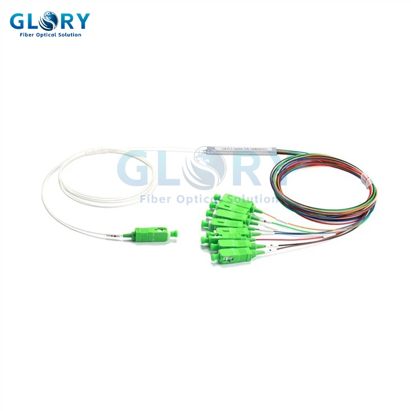
Compact integration
Blockless PLC Splitter Family
Suitable for splice trays, compact distribution boxes and custom assemblies. Order fields include 1×N or 2×N ratio, G.657 fiber, tube or cable diameter, leg length and connectorization.
Temperature review: qualify the mini-module and the final enclosure routing as one installation system.
View product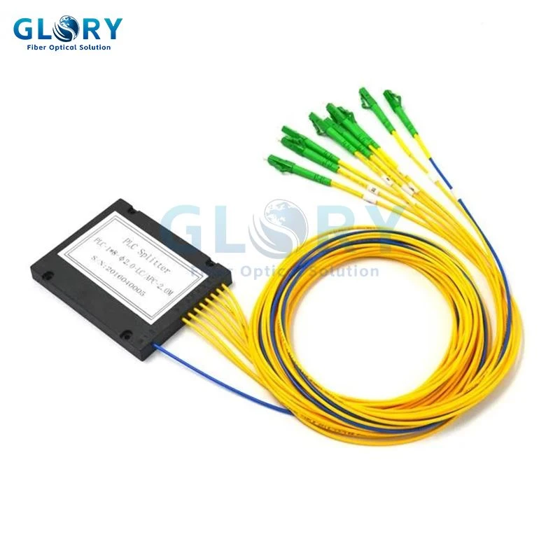
Protected module
1×8 ABS Box PLC Splitter
The page publishes separate insertion-loss limits with and without connector loss and an operating range of −40°C to +85°C for the listed configuration.
Temperature review: request evidence for the complete ABS housing, pigtails, strain relief and selected connectors.
View product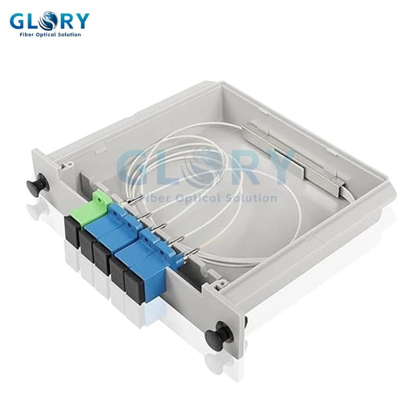
Modular plug-in format
PLC Splitter Cassette
The listed 1×4 cassette page states a working range of −40°C to +85°C and a maximum temperature-stability value of 0.6 dB.
Temperature review: confirm whether the declared ΔIL covers the complete connectorized cassette and the exact requested ratio.
View product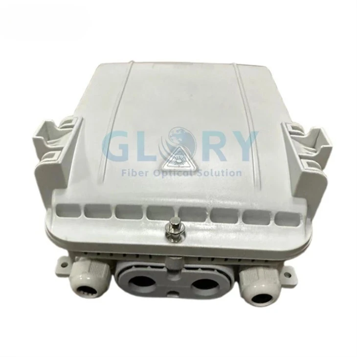
Outdoor integrated terminal
GL-DH-P1-8C Splitter Terminal Box
This IP65 PC+ABS terminal integrates one 1×8 insertion-module PLC splitter with eight pre-connected SC/APC output paths.
Temperature review: combine splitter evidence with enclosure exposure, internal routing, adapters and the site's thermal conditions.
View productFor project-specific loaded configurations, Glory's OEM/ODM service can freeze the approved splitter package, enclosure, connector interface, drawing, test plan and batch traceability before production.
Frequently Asked Questions
Q: What is the normal operating temperature of a PLC splitter?
A: There is no single approved range for every PLC splitter. Many products publish ranges near −40°C to +85°C, but the applicable limit depends on the exact package, connectorization and project datasheet.
Q: Why can a temperature-stability test range be wider than the operating range?
A: A temperature-stability range may describe the exposure span used to measure ΔIL, while the operating range defines approved field service. A wider test span does not extend the operating rating unless the supplier documents that approval for the exact package.
Q: Which IEC environment category applies to an outdoor PLC splitter?
A: IEC 61753-031-2:2014 addresses non-connectorized branching devices for Category C controlled environments, while IEC 61753-031-3:2014 addresses Category U uncontrolled environments. The project should cite the exact product standard and edition and confirm that the tested package matches the installation microenvironment.
Q: Can a splitter pass room-temperature inspection and still cause a seasonal problem?
A: Yes. A reversible insertion-loss increase can appear while the device is hot or cold and reduce after room-temperature recovery. Before-and-after room-temperature results can therefore miss operating-state loss.
Q: How should temperature-dependent loss be included in an optical budget?
A: Add the supplier-declared maximum per-port ΔIL to the worst subscriber path, using the same package and wavelength basis. Keep the temperature-drift allowance separate from connector, ageing, repair and measurement reserves.
Q: Which PLC splitter package should be tested?
A: The evidence should match the ordered construction. A blockless module, ABS box, connectorized cassette and enclosure-integrated splitter should not automatically share one qualification conclusion.
Conclusion
A PLC splitter operating-temperature line is only one part of approval. The defensible procurement question is whether the exact shipped package has environment-matched evidence, quantified per-port ΔIL during exposure and sufficient worst-path optical margin after that change is included.
Standards and Technical References
- Y. Zheng et al., "Novel Research on Reliability of Silica-Based PLC Optical Splitters," Optik, Vol. 178, 2019, pp. 1294–1301, DOI: 10.1016/j.ijleo.2018.10.119.
- IEC 61753-031-2:2014, non-connectorized single-mode 1×N and 2×N non-wavelength-selective branching devices for Category C controlled environments.
- IEC 61753-031-3:2014, non-connectorized single-mode 1×N and 2×N non-wavelength-selective branching devices for Category U uncontrolled environments.
- IEC 61753-1:2018, general and guidance for passive-fiber performance standards.
- Telcordia GR-1209-CORE, generic requirements for passive optical components; verify the project-required issue.
- Telcordia GR-1221-CORE, reliability assurance for passive optical components; verify the project-required issue.
- ISO/IEC 17025:2017, general requirements for the competence of testing and calibration laboratories.