The short answer
Use G.657.A2 selectively in the FTTH sections with the highest bend exposure: building-entry turns, narrow indoor raceways, compact wall outlets, termination boxes and ONT pigtails. G.657.A1 remains a practical option for longer routes where supports, service loops and enclosure storage keep the finished cable within its approved limits.
The purchasing decision belongs at the finished-cable level. Fiber category, cable dimensions, jacket stiffness, strength members, connector boots, pulling load and enclosure geometry determine the field result.
1. What G.657.A1 and G.657.A2 Actually Change
The current ITU-T G.657 Recommendation (08/2024) classifies A1 and A2 as Category A bend-loss-insensitive single-mode fibers. Category A requirements are a subset of G.652.D, preserving the transmission and interconnection characteristics needed in access links that also contain G.652.D fiber.
The principal difference is the small-radius macrobending requirement.
| Fiber category | Minimum design radius in ITU-T G.657 | Engineering meaning | Typical procurement use |
|---|---|---|---|
| G.657.A1 | 10 mm | Bend resilience for routes with controlled cable management | Distribution, riser, outdoor drop and general access sections |
| G.657.A2 | 7.5 mm | Stricter small-radius macrobending limits for confined or variable routing | Indoor drop, compact boxes, pigtails and dense customer-side routing |
Macrobending limits under the standard test conditions
| Fiber category | Test radius | Turns | Maximum macrobending loss at 1550 nm |
|---|---|---|---|
| G.657.A1 | 15 mm | 10 | 0.25 dB |
| G.657.A1 | 10 mm | 1 | 0.75 dB |
| G.657.A2 | 15 mm | 10 | 0.03 dB |
| G.657.A2 | 10 mm | 1 | 0.10 dB |
| G.657.A2 | 7.5 mm | 1 | 0.50 dB |
Glory's fiber optic cable bend-limits guide explains the difference between fiber-grade tests and complete-cable handling limits.
Relationship to Glory's broader standards guide
This page focuses on the procurement boundary between G.657.A1 and G.657.A2. For the wider standards-family comparison covering G.652.D, G.657.A1, G.657.A2 and G.657.B3, use Glory's published Fiber Optic Cable Types and Standards Guide. Keeping the two intents separate reduces overlap: the standards guide explains the fiber families, while this page converts A1/A2 differences into route-level purchasing decisions.
2. Select Fiber at Each FTTH Route Transition
Indoor and outdoor labels provide only an initial clue. A wide indoor riser may impose less bend stress than a compact outdoor terminal, while a wall-entry turn may be more severe than the indoor raceway that follows it. Set the fiber category wherever the route geometry or enclosure changes.
| FTTH section | Initial fiber preference | Release question | Glory product or guide |
|---|---|---|---|
| Feeder or distribution route | G.652.D or G.657.A1 | Is the path long, protected and free from small-radius handling? | Fiber optic cable range |
| Outdoor aerial or façade drop | Usually G.657.A1; A2 where local geometry is tight | Do clamps, wall transitions or service loops create a smaller local radius? | ROC drop cable |
| Building-entry transition | G.657.A1 or A2 after route review | Can the approved cable radius be maintained through the penetration and strain relief? | Pre-terminated route survey guide |
| Indoor horizontal drop | G.657.A2 preferred for compact routes | Are there raceways, door frames, skirting boards or crowded conduits? | FTTH drop cable range |
| Fiber wall outlet | G.657.A2 often preferred | Can the pigtail and drop cable be stored clear of the cover and adapter bodies? | Fiber optic wall outlets |
| Compact termination box | G.657.A2 often preferred | Does the loaded tray and adapter layout preserve the cable radius? | Fiber optic termination boxes |
| ONT pigtail or short jumper | G.657.A2 preferred | Will the fiber form a short U-bend behind the ONT or wall outlet? | LC single-mode pigtail |
Where G.657.A1 is normally sufficient
A1 is a defensible specification when supports and slack loops are dimensioned correctly, enclosure storage is generous, the route remains above the finished cable's approved radius and post-installation handling is limited.
The linked Glory ROC drop cable page lists G.657.A1 and G.657.A2 fiber options. Its published structure includes a 3.0 × 6.0 mm PE outer sheath, two 1.2 mm FRP strength members and a 0.5 mm bare-copper toning conductor. These construction details belong in the review alongside the fiber category.
Where G.657.A2 creates measurable design value
A2 becomes more valuable near the subscriber endpoint, especially where the route contains repeated corners, shallow raceways, compact wall outlets, uncertain retrofit conduits or short pigtails stored behind adapters.
The ITU-T L.111 in-home cable guidance includes G.657.A2 or B3 in minimum-visibility in-home cable examples, supporting tighter-bend fiber in the final customer-side section when the pathway requires it.
3. Glory Route-Risk Screening Model for A1 and A2
The following quotation-stage model is an original Glory planning framework used alongside ITU-T G.657, the finished-cable data sheet and local installation requirements. Score each route section from 0 to 2 in four categories.
| Risk factor | 0 points | 1 point | 2 points |
|---|---|---|---|
| Expected route radius | Above 15 mm | 10–15 mm | Below 10 mm or unconfirmed |
| Installation space | Open tray or wide duct | Standard box or raceway | Compact outlet, dense tray or crowded conduit |
| Installation control | Planned and supervised | Partially controlled | Retrofit or installer-dependent |
| Post-installation handling | Rarely accessed | Periodic maintenance | Repeated activation, movement or user handling |
| Total score | Preliminary decision | Required release action |
|---|---|---|
| 0–2 | G.657.A1 is generally sufficient | Confirm the finished-cable static and dynamic bend limits |
| 3–5 | A1/A2 engineering review | Compare sample cables, route geometry and enclosure routing |
| 6–8 | G.657.A2 normally preferred | Approve A2 or reduce bend exposure through route redesign |
Example: controlled building entry
A 12 mm entry bend, standard termination box, supervised installation and periodic maintenance score 4 points. Hold the fiber choice for engineering review and compare the approved cable radius with the penetration geometry and loaded-box drawing.
Example: shallow ONT outlet
An uncertain sub-10 mm bend, limited storage, installer-dependent routing and repeated handling score 7 points. G.657.A2 is the stronger preliminary choice, with the enclosure layout preserving the finished-cable radius.
4. Allocate A2 Where It Changes Risk, Then Compare the Real Volume
A2's commercial value becomes measurable after the route is divided into low- and high-bend-risk sections. Consider an illustrative 1,000-subscriber design.
| Section per subscriber | Length | Proposed category | Reason |
|---|---|---|---|
| Outdoor distribution-to-entry drop | 40 m | G.657.A1 | Long, planned route with controlled supports |
| Indoor entry-to-wall-outlet cable | 12 m | G.657.A2 | Multiple corners and limited raceway space |
| Wall-outlet-to-ONT pigtail | 1 m | G.657.A2 | Compact U-bend and repeated access |
The project price will change by a smaller percentage because fiber is only one input in a finished cable or assembly. Jackets, reinforcement, connectors, production setup, test requirements, packing and order quantity can dominate the final quotation.
Request two quotations with the same cable construction and change only the fiber category. This produces a meaningful A1/A2 comparison and avoids mixing an outdoor PE/FRP A1 cable with an indoor LSZH/aramid A2 cable.
5. Pair the Fiber Grade with the Finished-Cable Specification
The IEC 60794-1-1:2023 generic cable specification establishes uniform requirements covering geometry, transmission performance, materials, mechanical properties, ageing and environmental exposure. These cable-level controls apply to A1 and A2 alike.
A complete specification should define:
- indoor, outdoor or indoor/outdoor application;
- flat, round, bow-type, ROC or pre-terminated construction;
- cable dimensions and manufacturing tolerances;
- PE, LSZH, PVC, TPU or project-specific jacket;
- FRP, steel wire, aramid yarn or other strength member;
- static and dynamic finished-cable bend radius;
- short-term and long-term tensile limits;
- temperature, UV, moisture, flame and water-blocking requirements;
- connector type, polish and boot geometry;
- sample approval, batch test evidence and traceability.
Engineering rule
The fiber category controls optical bend resilience. The cable construction controls how safely that resilience can be used in the field.
For pre-connectorized routes, connector dimensions and pulling protection may become the governing constraints. Glory's pre-terminated fiber route survey guide covers conduit clearance, pull points, bend review and termination space before production.
6. Validate G.657.A1, G.657.A2 and G.652.D Splices as a System
Category A fibers support G.652.D transmission and interconnection requirements, allowing A1, A2 and G.652.D to appear in the same access link. Project-specific splice evidence remains necessary because the actual result depends on the selected fibers and process.
Fusion-splice performance depends on the mode-field diameter, refractive-index profile, cleave quality, cleanliness, splicer alignment, arc calibration, program and OTDR measurement direction.
Corning's AN2020 fusion-splicing report covers Corning SMF-28 Contour family fibers, including G.652.D-, G.657.A1- and G.657.A2-compliant variants, and reports product-pair results obtained with a Fujikura 90S core-alignment splicer using the SM-AUTO program. As one documented example, SMF-28 Contour to SMF-28 Ultra produced a mean bidirectional loss of 0.02 dB at 1310, 1550 and 1625 nm, with maxima of 0.05, 0.04 and 0.04 dB respectively. Treat these values as evidence for those Corning products and test conditions.
Recommended sample-validation sequence
- Record the fiber manufacturer and type used in every cable section.
- Review the supplier's stated mode-field diameter and attenuation limits.
- Prepare representative A1-to-A2 and G.652.D-to-G.657 splices.
- Use the intended production splicer and approved program.
- Measure each event from both directions with an OTDR.
- Average the two directions before judging splice loss.
- Retain the splicer model, program, operator, fiber batch and trace file.
Glory's LC single-mode pigtails support customized fiber type, connector polish, length and jacket options. State the pigtail fiber category in the BOM for a mixed A1/A2 route.
7. Turn the Fiber Decision Into a Quote-Ready FTTH RFQ
A useful RFQ defines the function and installation condition of every route segment.
| RFQ field | What the buyer should specify |
|---|---|
| FTTH segment | Outdoor drop, building entry, indoor drop, wall outlet or ONT pigtail |
| Fiber category | G.657.A1 or G.657.A2, referenced to the current ITU-T G.657 edition |
| Finished product | Flat drop, round drop, ROC cable, pigtail or pre-terminated assembly |
| Cable dimensions | Nominal dimensions and tolerances |
| Jacket and strength members | PE, LSZH, PVC or TPU; FRP, steel or aramid as applicable |
| Static and dynamic bend limits | Supplier values for the finished cable or assembly |
| Tensile requirement | Short-term and long-term values with the applicable test method |
| Optical acceptance | Wavelengths, maximum attenuation and splice/connector limits |
| Environmental evidence | Temperature, UV, water, flame and mechanical tests required by the route |
| Sample validation | Mixed-fiber splice test or route mock-up before production |
| Traceability | Fiber batch, cable reel and assembly serial record |
Example FTTH RFQ opening statement
Provide G.657.A1 outdoor drop cable from the distribution point to the building entry and G.657.A2 indoor drop and pigtail assemblies from the entry point to the ONT. Quote the same finished-cable construction in A1 and A2 where comparison is required. Submit the fiber declaration, finished-cable bend limits, applicable IEC 60794 test evidence, batch optical report and representative mixed-fiber splice results.
Special A2 application note: FPV drone fiber
FPV remains outside the article's primary FTTH keyword scope, so it is treated here as a compact application example. A drone tether places nearly the complete fiber length through winding and dynamic payout, making end-to-end G.657.A2 a practical baseline for Glory's published FPV systems.
| Glory model | Verified public specification | Procurement implication |
|---|---|---|
| GL-FPV-M30 | G.657.A2; 0.27 mm standard fiber diameter; 3, 5, 10, 15, 20 and 30 km options; FC/ST/SC/LC compatibility | Prioritize reel weight, length, payout system and interface alongside the fiber grade |
| GL09-GXT | 260 ±15 μm / 30 km / >55 N; 300 ±15 μm / 20 km / >55 N; 350 ±20 μm / 15 km / >80 N; all G.657.A2 | Increasing reinforcement raises tensile capability while reducing stored length for a given system envelope |
Use Glory's FPV optic drum and cable buyer's guide for the full FPV selection workflow and the FPV product range for current model options.
8. Recommended Glory Products for the A1/A2 Procurement Workflow
The first two cards support the FTTH route addressed by this article. The third card links the separate FPV range as a related G.657.A2 application.
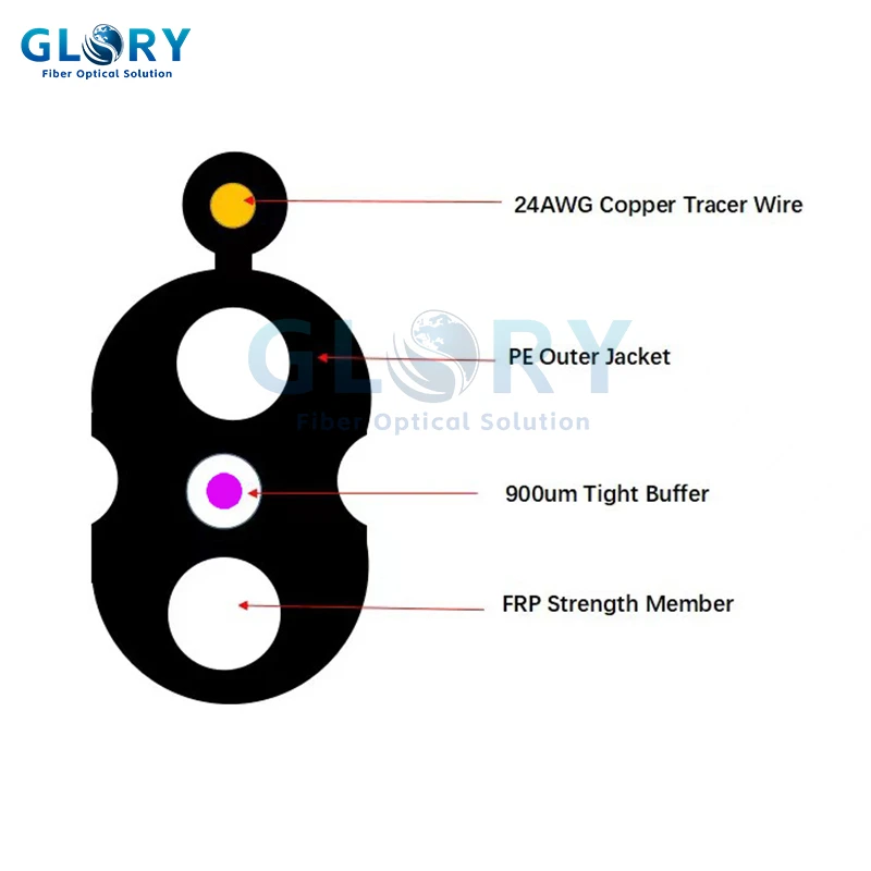
Outdoor FTTH Segment
ROC Drop Cable - G.657.A1 or G.657.A2
The linked specification lists a 3.0 × 6.0 mm PE sheath, two FRP strength members and a bare-copper toning conductor. Select A1 or A2 after reviewing supports, entry turns and slack storage.
View product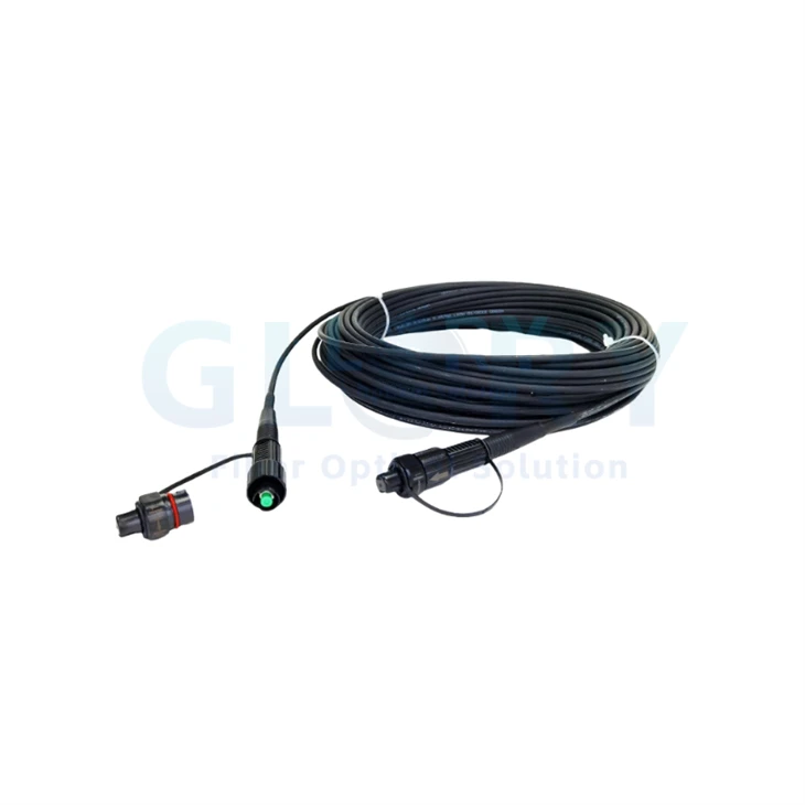
Factory-Terminated FTTH Transition
Pre-Terminated Fiber Optic Drop Cable
The public page lists G.657.A1, G.657.A2 and G.657.B3 options with customized cable length and Mini-SC/APC termination choices. Approve the connector envelope, route and terminal space before production.
View product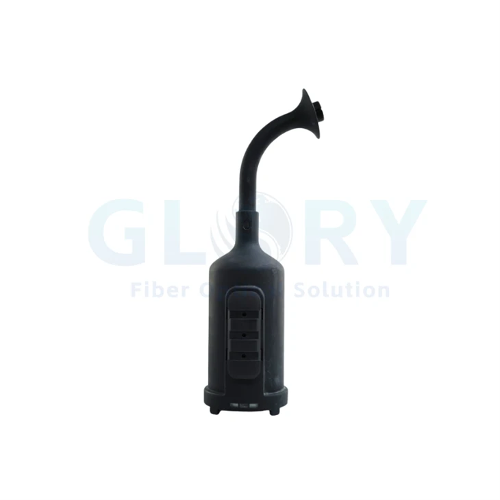
Related G.657.A2 Application
FPV Drone Fiber Optic Cable Range
Includes the lightweight GL-FPV-M30 and the GL09-GXT inner-winding system. Use the separate FPV guide to compare coated-fiber diameter, reel length and tensile protection.
View rangeConvert the route into an A1/A2 cable and assembly BOM
Send Glory the outdoor and indoor route lengths, pathway dimensions, cable-entry direction, enclosure model, connector interface, pulling method and required test documents.
Request a quotationReview OEM/ODM optionsContact technical sales
Frequently Asked Questions
Q: Is G.657.A2 always better than G.657.A1?
A: G.657.A2 offers stronger small-radius macrobending performance. G.657.A1 remains suitable for routes where the finished cable stays within its approved bend limits and installation control is reliable.
Q: Can G.657.A1 and G.657.A2 be used in the same FTTH link?
A: Yes. Both are Category A fibers under ITU-T G.657 and support G.652.D transmission and interconnection requirements. Validate representative mixed-fiber splices with the intended fibers, splicer program and bidirectional OTDR method.
Q: Should indoor FTTH cable always use G.657.A2?
A: Use G.657.A2 where indoor routing includes compact outlets, repeated corners, shallow raceways or uncertain installer handling. A wide and controlled riser may remain suitable for G.657.A1.
Q: Does the 7.5 mm A2 design radius set the cable installation radius?
A: The 7.5 mm value classifies G.657.A2 fiber under defined test conditions. Field installation follows the finished-cable static and dynamic bend limits stated by the cable manufacturer.
Q: How should a building-entry transition be specified?
A: Keep G.657.A1 when the approved cable radius can be maintained through the wall entry and strain relief. Select G.657.A2 when the transition is tighter, uncertain or constrained by a compact enclosure.
Q: What documents should be requested for G.657.A1 or G.657.A2 cable?
A: Request the fiber compliance declaration, finished-cable data sheet, applicable IEC 60794 test evidence, batch optical results, approved drawing and traceability records. Pre-terminated assemblies should also include connector insertion-loss and return-loss results.
Standards, Data Sources and Methodology
This article combines current standards, Corning's product-specific application note, public Glory specifications and two transparent planning models. The 1,000-subscriber length calculation and four-factor route-risk score are engineering examples created for quotation-stage screening.
- ITU-T G.657 (08/2024): Characteristics of a bending-loss-insensitive single-mode optical fibre and cable
- ITU-T L.111: Optical fibre cables for in-home applications
- IEC 60794-1-1:2023: Optical fibre cables - Generic specification - General
- Corning AN2020: SMF-28 Contour Optical Fiber Fusion Splicing Report
- Glory Optical: Fiber Optic Cable Types and Standards Guide
- Glory Optical: Fiber Optic Cable Bend Limits
- Glory Optical: Pre-Terminated Fiber Optic Cable Route Survey
- Glory Optical: FPV Optic Drum and FPV Optic Cable Buyer's Guide