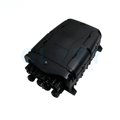
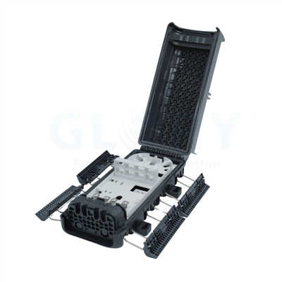
Product overview
8-Core Fiber Optic Splitter Terminal Box for FTTH Access Points
The GL-DH-P1-8C combines feeder-cable termination, fiber routing, passive splitting and pre-connected subscriber distribution inside one compact outdoor enclosure. The insertion-module layout presents one 1×8 PLC splitter to SC/APC output interfaces while keeping the field-access and cable-management areas organized.
Network function
Install the terminal between an upstream distribution cable and as many as eight planned subscriber drops at an FTTH user-access point. It is a passive branch terminal: the 1×8 split ratio determines the optical fan-out, while the eight-core capacity identifies the supported distribution scale.
Configuration at a glance
The enclosure holds one 1×8 splitter and presents pre-connected SC/APC outputs through a 4/12 inlet/outlet arrangement. Add the cable specifications, splitter optical limits, fiber standard and mounting accessories to the project BOM before ordering.
Capacity is not the same as the molded inlet/outlet count
The active subscriber distribution capacity is eight cores through the 1×8 PLC configuration. Treat "4/12" as the enclosure entry/exit arrangement and use the approved port map or drawing when assigning feeder, branch and subscriber cables.
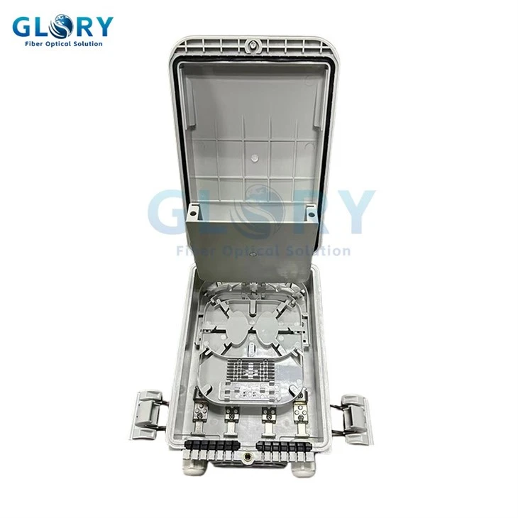
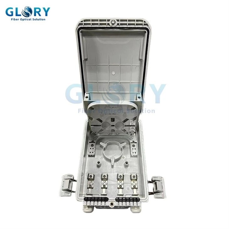
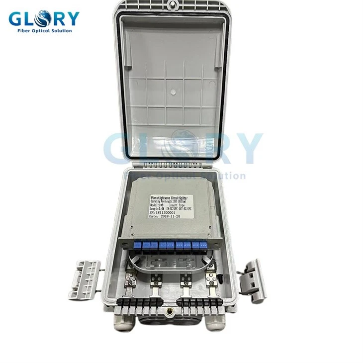
One 1×8 insertion-module PLC splitter installed above the SC/APC interface area.
Design details
GL-DH-P1-8C Product Features
Each point below ties a defined structure or specification to a practical installation or purchasing decision.
One 1×8 Insertion-Module PLC Splitter
The internal drop leaf accepts one 1×8 insertion-module PLC splitter, creating eight distribution paths from one input. The removable module format gives the project a defined splitter position and ratio, but the splitter model and qualified optical-loss data must still be confirmed on the order.
Pre-Connected SC/APC Subscriber Outputs
The incoming optical cable is converted to single-core SC/APC output interfaces. When supplied with matching pre-connected drop cables, subscriber connections can be made without opening the enclosure or fusion-splicing each service drop, reducing the field steps at the access point.
External Cable Fixing and Side Outputs
A quick-insertion mechanism fixes and seals the optical cable outside the connection area, while output positions are provided on both sides of the enclosure. This layout keeps cable handling separate from the internal fiber path; the RFQ should still identify every cable and its assigned entry or exit.
IP65 PC+ABS Enclosure
The PC+ABS housing carries an IP65 rating and is available in black or gray. This gives outdoor planners fixed material, color and ingress-protection fields for pole, wall or aerial nodes; IP65 does not establish unlimited immersion or an impact rating.
242 × 167 × 93 mm, 0.65 kg Body
The compact 242 × 167 × 93 mm enclosure weighs 0.65 kg. These values let engineers check pole clearance, wall space, messenger loading and carton planning before approval, instead of selecting the terminal only by its eight-core capacity.
Wall, Pole and Messenger Mounting
The enclosure supports wall mounting, pole mounting and hanging from a messenger cable. One terminal platform can therefore cover building-side, utility-pole and aerial FTTH access nodes, provided the order includes the site-specific bracket, hanging hardware, orientation and cable-support method.
Product configuration
Product Configuration and Ordering Fields
The GL-DH-P1-8C is defined here as one 8-core, 1×8 SC/APC configuration. Project-specific fields should be frozen through an approved drawing, splitter datasheet, cable schedule and BOM.
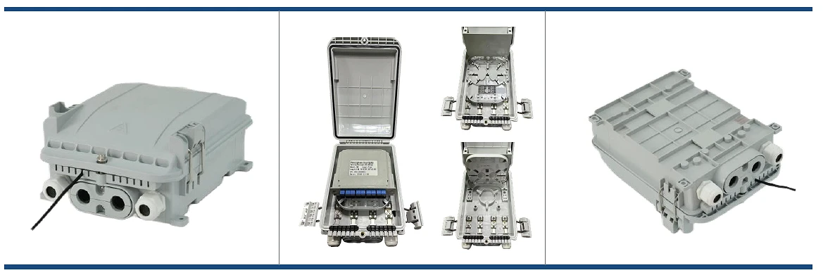
Closed, open, internal and rear views of the GL-DH-P1-8C enclosure.
Technical data
Fiber Optic Splitter Terminal Box Technical Specifications
The tables separate enclosure capacity, splitter configuration, connector interface and packaging so that physical port counts are not treated as optical performance values.
General Technical Specifications
Product, enclosure, protection, installation and packaging data.
| Item | Specification | Project Selection Note |
|---|---|---|
| Product name | Fiber Optic Splitter Terminal Box | Use with the model number and approved product image or drawing. |
| Product model | GL-DH-P1-8C | Do not mix values from GL-P1-16R2, GL-P2-16R2, MTC, MTS, MTT or other terminal families. |
| Product family | 8-core outdoor fiber optic splitter terminal box | Passive FTTH user-access and feeder-to-drop distribution point. |
| Fiber capacity | 8 cores | Capacity is separate from the physical inlet/outlet listing. |
| Splitter capacity | 1 piece of 1×8 insertion-module PLC splitter | Confirm the splitter model, connectorization and qualified optical report. |
| Connector interface | Pre-connected SC/APC outputs | Confirm mating drop-cable connector and dust-cap arrangement. |
| Inlet/outlet | 4/12 | Request the approved port map; do not interpret this value as twelve active subscriber outputs. |
| Enclosure material | PC+ABS | Record the approved material and housing revision in the project BOM. |
| Dimensions | 242 × 167 × 93 mm | Check opening clearance, cable bend space and mounting surface. |
| Weight | 0.65 kg | Product weight; mounting and cable load must be evaluated separately. |
| Color | Black / gray | State the selected color on the RFQ and approved drawing. |
| Protection rating | IP65 | Does not indicate unlimited immersion; match site exposure to the stated rating. |
| Mounting method | Wall, pole or messenger-cable hanging | Specify bracket, hanging set, fasteners, orientation and cable support. |
| Package quantity | 20 pieces per carton | Confirm the order revision and whether accessories are packed with each unit. |
| Carton size | 52 × 38.5 × 53 cm | Use the confirmed packing list for final freight calculations. |
| Carton weight | Gross 16.5 kg; net 15.38 kg | Carton-level values for the 20-piece pack. |
Model and Capacity Table
Model, capacity, splitter, interface and enclosure dimensions are kept as separate selection fields.
| Model | Fiber Capacity | Splitter | Subscriber Output Interface | Inlet/Outlet Listing | Dimensions |
|---|---|---|---|---|---|
| GL-DH-P1-8C | 8 cores | 1 piece, 1×8 insertion module | SC/APC, pre-connected | 4/12 | 242 × 167 × 93 mm |
Splitter Configuration Table
| Splitter Format | Quantity | Split Ratio | Input / Output Paths | Output Interface | Optical Data Required for Order |
|---|---|---|---|---|---|
| Insertion-module PLC | 1 piece | 1×8 | 1 input / 8 outputs | SC/APC | Confirm insertion loss by port, return loss, uniformity, PDL, directivity, operating wavelength and fiber type on the selected splitter datasheet or test report. |
Cable and Connector Compatibility
| Compatibility Field | Standard Configuration | Information to Confirm |
|---|---|---|
| Upstream cable function | Connects distribution cable to drop cable at an FTTH user-access point | Cable construction, fiber count, outside diameter, strength member and assigned inlet. |
| Subscriber drop connection | Pre-connected household drop cable | Cable profile, outside diameter, length, connector boot, polarity and sealing fit. |
| Connector type | SC/APC output interface | Confirm the matching SC/APC drop connector; do not substitute SC/UPC without an approved optical design. |
| Entry/exit structure | 4/12 inlet/outlet listing; side output positions; external quick-insertion fixing | Approved drawing, cable-to-port map, plug or cap arrangement and sealing parts. |
Optical specification boundary
The enclosure's IP rating, dimensions and weight are not optical-loss values. Connector insertion loss, mated-pair loss, return loss and the actual worst-port loss of the 1×8 splitter must be assigned to the selected connectorized splitter assembly and verified with its stated test conditions.
Network placement
Fiber Optic Splitter Terminal Box Applications and Solutions
The GL-DH-P1-8C fits compact passive access nodes where one feeder path must be split into eight managed SC/APC subscriber connections.
FTTH Last-Mile Distribution
A generic splice box can force technicians to splice every subscriber drop and reopen the enclosure whenever a household is connected. The GL-DH-P1-8C uses one 1×8 insertion-module PLC splitter and pre-connected SC/APC outputs to move subscriber activation to an external mating point. Install it between the distribution cable and up to eight planned drop routes at a neighborhood user-access node. Before procurement, confirm the feeder cable construction, matching SC/APC drop assemblies, cable-to-port map, splitter loss report, mounting method and the number of homes actually included in the optical budget.
Pole-Mounted Outdoor FTTH Nodes
Selecting an indoor enclosure for a utility pole leaves the cable entry, attachment method and exposure rating unresolved. The GL-DH-P1-8C provides an IP65 PC+ABS housing and a defined pole-mount option for compact outdoor distribution. Mount it at a feeder-to-drop branch point where the upstream cable enters the terminal and SC/APC subscriber drops leave toward nearby premises. Buyers should define the pole diameter, bracket and fasteners, mounting orientation, cable support, actual cable diameters, unused-port caps and whether the site's water or impact exposure exceeds the stated enclosure rating.
Aerial Messenger-Cable Distribution
Using a wall-only box on an aerial route can transfer cable and wind load into housing features that were not selected for suspension. The GL-DH-P1-8C supports messenger-cable hanging and weighs 0.65 kg before cables and hardware are added. Position it on an aerial FTTH distribution route where one passive input feeds eight SC/APC service paths. The project schedule should state the messenger size, suspension hardware, span conditions, cable support, terminal orientation, feeder and drop cable profiles, clearance for opening the cover and the required sealing parts for every occupied or unused position.
GPON or XGS-PON 1×8 Branch Points
Choosing a terminal only by protocol name can hide the splitter loss and connector events that determine whether each ONT receives enough power. The GL-DH-P1-8C provides the passive 1×8 branch function used in point-to-multipoint PON layouts and presents the outputs on SC/APC interfaces. Install it at the outdoor or building-side access node defined by the ODN design, upstream of subscriber drop cables and ONTs. Procurement must confirm the OLT class and link budget, splitter test data, connector-pair allowances, fiber type, drop lengths, reserve margin and whether a single-stage or cascaded split architecture is intended.
Project ordering
Ordering Configuration
Include these fields in the RFQ so the delivered terminal matches the optical budget, cable schedule, mounting location and subscriber-drop interface.
| Ordering Field | Standard Information | Information to State on the RFQ |
|---|---|---|
| Product identifier | GL-DH-P1-8C fiber optic splitter terminal box | Model, order quantity and approved product image or drawing revision. |
| Fiber capacity | 8 cores | Active subscribers, reserved outputs and the complete ODN branch plan. |
| PLC splitter | 1 piece of 1×8 insertion module | Splitter model, optical limits, wavelength, fiber type, connectorization and test report. |
| Subscriber interface | SC/APC pre-connected outputs | Mating drop-cable connector, cable profile, length, boot, cap and labeling. |
| Cable entries | 4/12 inlet/outlet listing | Approved port map plus cable quantity, construction and OD at every position. |
| Housing | PC+ABS; IP65; black or gray | Selected color, site exposure and any required material or ingress inspection. |
| Mounting | Wall / pole / messenger-cable hanging | Actual site, bracket, fasteners, hanging set, orientation and cable-support parts. |
| Dimensions and weight | 242 × 167 × 93 mm; 0.65 kg | Confirm against the approved drawing and installation-space check. |
| Identification | Project-defined | Housing label, output numbers, cable tags, lot code, barcode and logo artwork. |
| Packaging | 20 pieces; 52 × 38.5 × 53 cm carton; 16.5 kg gross / 15.38 kg net | Accessory packing, carton marks, palletization and packing-list format. |
| Documents | Project-defined | Datasheet, approved drawing, splitter report, inspection record, packing list and requested compliance documents. |
Recommended RFQ line
GL-DH-P1-8C 8-core outdoor fiber optic splitter terminal box, PC+ABS, IP65, black/gray [select], one 1×8 insertion-module PLC splitter, SC/APC pre-connected outputs, feeder cable [construction / OD], drop cable [profile / connector / length], port map [revision], mounting [wall / pole / messenger], hardware [ ], labels [ ], optical report [ ], inspection documents [ ] and packaging [ ].
OEM and project support
OEM Fiber Optic Splitter Terminal Box Configuration
For project orders, control the enclosure, splitter, SC/APC interfaces, cable-entry parts, mounting hardware, labels and packaging through one approved drawing and BOM.
Housing and Port Review
Review the 242 × 167 × 93 mm housing, 4/12 inlet/outlet drawing, side outputs, latches, cable-fixing parts and mounting points before sample approval.
Splitter Integration
Define the 1×8 insertion module, SC/APC connectorization, fiber routing, port numbering and requested optical-test fields as one loaded configuration.
Cable and Connector Fit
Match the feeder and drop cable construction, OD, connector boot and cap to the selected entries and subscriber interfaces.
Mounting Package
Prepare wall, pole or messenger hardware against the actual structure, orientation, cable load and opening clearance stated by the project.
Sample Confirmation
Approve dimensions, color, port map, splitter seating, SC/APC mating, cable retention, hardware and the requested inspection procedure before batch supply.
Labels and Packaging
Confirm logo artwork, product label, subscriber-port numbering, cable tags, lot identification, carton marks and accessory packing instructions.
Company background
Glory Optical Manufacturing and Project Support
Founded in 2008 and based in Ningbo, Zhejiang, Ningbo Glory Optical Communication Co., Ltd. lists a 20,000 m² manufacturing facility, more than 300 passive optical products, supply to over 50 countries and OEM/ODM support for passive fiber infrastructure projects.
Enclosure and Component Production
Glory Optical handles raw-material inspection, cable production, connector assembly, enclosure injection molding, splitter processing, quality testing and packaging. For this terminal, those processes meet at the PC+ABS housing, 1×8 PLC module and SC/APC output assembly.
Loaded-Terminal BOM Control
The GL-DH-P1-8C should be treated as a configured assembly rather than an empty box. The approved BOM can link the enclosure revision, splitter model, connector parts, cable-entry components, mounting accessories, labels and packing to the same project item.
Drawing and Sample Confirmation
Project support can cover drawing review, configuration confirmation, sample preparation, labeling and packaging. Buyers should use the sample stage to verify the physical port map, cable fit, splitter seating, SC/APC mating and site-specific mounting package.
Optical and Inspection Documents
The requested document set can identify the enclosure, loaded splitter, port numbering, optical measurements, inspection items and packing revision. Exact limits and sampling methods should be agreed on the order instead of inferred from the general product family.
Project checklist
Confirm the Splitter, Port Map and Drop Cable Before Ordering
Send the required subscriber count, feeder and drop cable construction, cable diameters, approved 4/12 port map, 1×8 splitter optical limits, SC/APC drop assemblies, mounting location, hardware, labels, inspection documents and packaging instructions.

Our Quality Promise
Comprehensive 3-Year Warranty
We confidently back all our products with a 3-year warranty. Our specific service policy is: within one year for quality issues, we take full responsibility for returns; within two years, for replacements; and within three years, for repairs.
Clear & Competitive MOQ
We welcome both trial and bulk orders. Our standard Minimum Order Quantity (MOQ) is 50 units. We also offer free samples for testing to help you evaluate our quality with confidence.
Fast & Reliable Logistics
We guarantee delivery within 10 days for standard items. Our logistics advantage includes cost-effective door-to-door service to simplify shipping for you.
Our Foundation
Backed by 18 years of experience since 2008, we control quality from our own factory, accept OEM/ODM requests, and maintain ready stock for wholesale. We focus on delivering the optimal balance of price and quality directly to end customers worldwide.
Your trust is our priority. Partner with us for dependable fiber optic solutions supported by clear promises.
Hot Tags: gl-dh-p1-8c fiber optic splitter terminal box, China gl-dh-p1-8c fiber optic splitter terminal box manufacturers, suppliers, factory, fiber distribution box, Fiber Optic Box Wall, fiber optic termination cabinet, Fiber Termination Enclosure, Mst Box, outdoor fiber distribution box