
Quick Answer: Can Home-Run FTTH Be Converted to PON?
Often yes. A usable conversion reserves suitable fibers as PON feeders, places PLC splitters at controlled FDH, FDB, NAP or closure locations and reconnects verified downstream fibers to the splitter outputs.
Approval depends on five connected checks: active-equipment compatibility, fiber continuity, nearest- and furthest-ONT optical levels, shared port capacity and a controlled cutover plan. Existing outside plant can remain valuable even when the OLT, ONTs and provisioning model change.
A Representative Brownfield Planning Scenario
Consider a planning scenario distilled from an anonymized engineering discussion: approximately 560 customer fibers leave a regional headend through three 288-fiber cables. Each residence originally received a dedicated strand through a chain of handholes. The design objective is to reuse installed cable, create field split nodes and release headend fibers and access ports for growth.
The commercial relevance is increasing as fiber markets mature. FTTH Council Europe reported about 295 million FTTH/B homes passed across EU39 in 2026, while the Fiber Broadband Association reported U.S. fiber availability above 60% of primary households in 2025. Dell'Oro expects PON revenue growth through 2030, driven largely by XGS-PON. These trends support more densification, ODN reuse and upgrade work alongside greenfield construction. FTTH Council Europe, Fiber Broadband Association, Dell'Oro Group
1. Define the Existing Home-Run Network Before Selecting Splitters
"Home-Run" can describe two different systems. The Fiber Optic Association uses Home-Run or active star for a point-to-point network in which every subscriber receives a dedicated fiber and Ethernet connection to the headend. The Fiber Broadband Association also documents a centralized Home-Run PON arrangement with splitters at the central office and one subscriber fiber extending through the outside plant.
| Existing network | Dedicated fiber terminates at | Likely conversion scope |
|---|---|---|
| Active Ethernet / P2P | Ethernet switch or individual optical port | Add a compatible PON OLT, migrate ONTs/CPE, build passive split nodes and change provisioning |
| Centralized Home-Run PON | CO or headend splitter | Move selected split functions into an FDH, FDB or closure and revise the ODN map |
| Poorly documented plant | Unverified equipment and field terminations | Audit wavelengths, active equipment, fibers and customer records before hardware release |
Adding a passive splitter to a point-to-point Ethernet transmitter will not create GPON or XGS-PON service. The OLT, ONTs and control plane must support the chosen PON technology. For the general relationship among feeder, distribution and drop layers, use Glory Optical's FTTH network design guide. This page stays focused on the brownfield conversion workflow.
Sources: FOA FTTH network design and FBA splitter architecture guide.
2. Use a Conversion Readiness Gate Before Hardware Release
Five approvals connect network design to a usable BOM. A failure in one category can change the split ratio, node placement, active platform or migration sequence.
| Gate | Required evidence | Release blocker |
|---|---|---|
| Active-system gate | OLT or switch model, optical class, ONT type, wavelength and provisioning method | Existing electronics cannot operate through the proposed PON |
| Fiber-reuse gate | Route map, live/spare list, splice records, measured length and fiber condition | No continuous feeder path or unsafe separation from live circuits |
| Optical gate | Nearest- and furthest-ONT loss calculations with stated margin | Receiver overload, inadequate sensitivity margin or incompatible optics |
| Capacity gate | Active customers, take rate, service tiers, busy-hour load and protection policy | Excess port loading or an unacceptable failure group |
| Operations gate | Node access, labels, port map, cutover window, tests and rollback path | Unmaintainable split nodes or uncontrolled outage exposure |
Glory can organize the passive inputs through its FTTH ODN network solution. The operator selects the active OLT and ONT platform; their optical class, connector interface and coexistence requirements become controlled inputs to the passive design.
3. Compare Splitter Architectures in the Context of the Retrofit
Installed fiber paths and service-area geometry usually narrow the choice more effectively than a generic preference for centralized or distributed splitting.
| Architecture | Feeder demand | Field hardware | Operational character | Brownfield fit |
|---|---|---|---|---|
| CO centralized Home-Run PON | High | Minimal outside split hardware | Flexible headend assignment | Short, fiber-rich plant where feeder release is not the main objective |
| Centralized FDH split | Low upstream; fiber-rich downstream | Cabinet or large FDB with one-stage PLC units | Visible ports and easier reassignment | Strong first candidate when existing downstream fibers fan out cleanly |
| Distributed split | Low | Smaller units in closures, FDBs, pedestals or NAPs | More access points and records | Useful when clusters follow existing handholes or pole routes |
| Cascaded split | Very low | Two or more splitter stages | More loss and troubleshooting locations | Useful for scattered routes after optical and maintenance review |
The FBA guide shows 1×4 followed by 1×8 as one way to reach an overall 1:32. Corning's public comparison describes the broader trade-off: centralized splitting can improve OLT utilization and reassignment flexibility, while distributed layouts reduce distribution fiber at the cost of more field nodes. FBA architecture guide, Corning FTTH architecture comparison.
For the 560-customer scenario, a controlled FDH or splitter closure is the first hypothesis to test. The installed 288F cables already provide downstream fiber richness, allowing one verified strand to feed a splitter while selected existing fibers carry outputs toward customer groups. The splice map and route survey decide whether that hypothesis survives.
Glory's PLC splitter range includes bare, blockless, ABS and cassette formats. Technology selection for low-count or unequal taps belongs in the separate FBT vs PLC splitter guide.
4. Reuse Existing 288-Fiber Cable with Controlled Strand Mapping
OLT PON port → verified feeder fiber → field splitter node → existing or new distribution fibers → drop fibers → ONTs
At each selected node, the feeder strand is accessed and connected to the PLC input. Outputs can return into available fibers in the same high-count cable, enter a new distribution cable or use both routes. The drawing must prove direction and continuity for every assigned strand.
Maintain two linked records: the fiber map shows physical strand continuity; the port map shows the logical OLT-to-ONT path.
| Asset | Reuse condition | Replacement or addition trigger | Evidence before release |
|---|---|---|---|
| Existing 288F cable | Continuous, tested fibers can be separated from live circuits | Route, condition or capacity is inadequate | Fiber ID, length, splice events and spare policy |
| Handhole or pole location | Space, access and permits support the node | The enclosure cannot be installed or maintained safely | Mounting, drainage, bend space and work clearance |
| Splice closure | Cable ports, trays, sealing and splitter space fit the arrangement | Mid-span access or splitter integration exceeds capacity | Cable diameter, tray loading, re-entry and IP requirement |
| Existing drops | Fiber grade, interface, route and loss remain suitable | Damage or ONT/interface change requires replacement | End-to-end loss, connector and premise termination |
| Distribution fibers | Routes match the proposed service area | Customer clusters require new lateral cable | Splitter-output-to-fiber-to-address mapping |
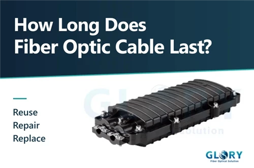
Where a new field access point is required, compare the drawing with the GL-GPJ09-9417-B splice closure. Its published configuration lists IP68 protection, 72 splice positions, space for two 1×8 or two 1×16 PLC modules and up to 16 hardened SC-compatible adapters. An eight-customer cluster can be screened against the GL-H60JF2(8) splitter splice closure. New feeder or lateral requirements can be matched through the outdoor cable range.
5. Calculate OLT Port Consolidation without Treating It as Final Quantity
For 560 active customer connections, the theoretical comparison is:
560
Point-to-point access ports
One dedicated active access port per customer.
18
1:32 PON ports
CEILING(560 ÷ 32) before growth and protection rules.
9
1:64 PON ports
CEILING(560 ÷ 64) before capacity and optical approval.
5 gates
Final approval
Active system, fiber, optical range, shared capacity and operations.
These figures describe consolidation potential. Construction quantities can be higher because of growth reserves, business-service separation, redundancy, protection groups and maintenance spares.
Shared capacity and fault exposure also grow with the split. Review service tiers, peak-hour demand, DBA policy, uplinks and restoration targets before loading a port. Glory can quote the passive package after the operator fixes these limits.
6. Let the OLT-to-ONT Optical Range Approve the Split Ratio
ITU-T G.984.1 states that a larger GPON split ratio requires an increased power budget. The 2019 edition of ITU-T G.984.2, Annex A, Table A.2, gives a 13–28 dB B+ loss range at both 1310 and 1490 nm. The selected OLT and ONT specifications remain the project limits.
Check both ends of the operating window
- Furthest or highest-loss ONT: confirm adequate sensitivity margin after ageing and repair allowance.
- Nearest or lowest-loss ONT: confirm received power remains below receiver overload.
The nearest-path check matters in short Home-Run retrofits. Low split counts, short fibers and few mating points can leave less than the minimum attenuation required by the optics.
For worksheet fields and handoff records, use Glory's FTTH GPON loss budget planning guide. The current 1×32 ABS PLC splitter page lists IL ≤17 dB, RL ≥55 dB and 1260–1650 nm for the shown configuration. The project acceptance sheet should identify connector inclusion, measurement wavelengths and the worst-port limit.
7. Build the Business Case from Avoided Assets and Added Field Work
Port reduction is only one part of the decision. A usable business case compares the value of reused plant and released headend capacity with the cost of electronics, field nodes, splicing, records and customer migration. Project-specific prices and route quantities are required before calculating payback.
| Business-case input | Favorable conversion signal | Cost or risk warning |
|---|---|---|
| Existing OSP value | High-count cable, handholes and drops are serviceable and well mapped | Unknown routes, damaged fibers or extensive remapping |
| Headend pressure | OLT/switch ports, frames, power or rack space constrain growth | Ample active capacity and no near-term expansion requirement |
| Active-equipment delta | Planned OLT/ONT refresh can absorb the migration | Large premature write-off of working P2P equipment |
| Field-node count | Customer clusters align with a limited number of maintainable nodes | Many new closures, permits, splices or difficult access points |
| Take rate and growth | Higher density can fill PON groups and release scarce feeder capacity | Sparse demand strands ports and weakens consolidation value |
| Cutover exposure | Customers can move in small documented batches with rollback | High-SLA users, narrow windows or poor service records |
| Upgrade horizon | The passive design supports the operator's GPON/XGS-PON plan | New coexistence filters or later rework consume the expected saving |
8. Build the Retrofit ODN BOM from the Approved Node Map
Separate reused assets, new passive components and operator-selected active equipment. Each line should trace to a node, interface, environment or acceptance requirement.
| Layer | Typical retrofit items | Release information |
|---|---|---|
| Headend | ODF ports, PON patch cords, pigtails, labels; operator-selected OLT/line cards | Optical class, connector, allocation and protection policy |
| Feeder | Reused/new outdoor cable, splice closure, trays, sleeves and slack hardware | Fiber count, cable diameter, route and spare rule |
| Split node | PLC splitter, FDH/FDB/NAP or splitter closure, adapters, mounting and seals | Ratio, package, polish, port map, environment and re-entry model |
| Distribution | Reused fibers or new distribution cable, closures and terminals | Service-area map, restoration spare and branch points |
| Drop | NAP/FAT ports, G.657 drop cable, premise box, pigtail and ONT lead | Length, route, interface and bend control |
| Evidence | Labels, IL/RL report, splice map, OLTS, OTDR and as-built BOM | Node ID, wavelength, acceptance limit and file format |
If the project team uses FDB, NAP, FAT and termination box interchangeably, review Glory's FDB vs NAP vs termination box comparison before model selection. Network role, port capacity, cable entries, interfaces and environment should drive the name and configuration.
9. Specify Qualification and Inspection Evidence before Ordering
PLC splitters can remain in service through temperature cycles, humidity, vibration and repeated maintenance access. Procurement should identify the evidence required for initial optical performance and longer-term reliability.
- Telcordia GR-1209 addresses generic requirements for passive optical components.
- Telcordia GR-1221 addresses reliability assurance for passive optical components.
- IEC 61300-3-35:2022 provides connector end-face inspection procedures and criteria.
- The FOA CFOS/D design certification is a useful competency benchmark for personnel reviewing route, budget and project controls.
Ask for the applicable declaration, qualification report or test evidence and verify that its scope matches the ordered package. Model, issue, sample, environment and report context determine whether a compliance statement is useful. Inspection should occur before mating and after field rework.
10. Migrate Customers in Controlled Batches with a Rollback Path
- Freeze the original fiber and active-port records.
- Build and test the feeder-to-splitter path before customer connection.
- Validate a near, typical and far path where practical.
- Migrate a small customer batch in a defined window.
- Confirm ONT registration, received power and service behavior.
- Update records before the next batch.
- Retain the rollback route until formal acceptance.
Customer address → ONT ID → drop fiber → NAP port → distribution fiber → splitter output → feeder fiber → OLT port
CableLabs documents the need to correlate OLT ports, ODN ports and the NAP chain, and to collect new records when customers move to new PON ports. CableLabs PON operations and maintenance report.
The FOA recommends including splitter loss in the link budget, testing appropriate wavelengths and retaining OTDR traces. It also shows how downstream traces combine branch signatures after a splitter, increasing the value of records created before activation. FOA FTTH testing guide.
11. Send a Drawing-Controlled Home-Run-to-PON RFQ
Network and active inputs
- Current Active Ethernet, GPON or XGS-PON topology
- OLT/ONT models, optical class and connector interface
- Customers, homes passed, take rate and growth horizon
- Shortest/longest paths and busy-hour capacity policy
Outside-plant inputs
- Route drawing, cable counts and usable fibers
- Centralized, distributed or cascaded arrangement
- Cabinet, pole, handhole, aerial, duct or burial environment
- Cable diameters, trays, mounting and sealing
Optical and interface inputs
- Split ratio, reservation policy and PLC package
- APC/UPC, adapters and hardened interfaces
- Loss budget, wavelengths and margin
- IL/RL report and end-face inspection requirements
Delivery and evidence inputs
- Node labels and port-map format
- OEM artwork and carton marks
- Project kit grouping
- As-built BOM, test files and batch traceability
Glory can review these fields through its ODN solution and BOM structure. The intended output is a passive package that reconciles with the operator's active-equipment, field-work and migration plans.
12. Glory Optical Product Starting Points
Use these pages to begin configuration review. Final supply follows the approved drawing, current datasheet, optical budget and project test requirements.
Turn the node map into a matched passive BOM
Send the route drawing, active platform, split plan, cable schedule, environmental conditions, port map and acceptance requirements. Glory Optical can review the PLC splitter, FDB/NAP, splice closure, cable and documentation package together.
Submit an RFQ Review OEM/ODM optionsFrequently Asked Questions
Q: Can I add a PLC splitter to an existing dedicated fiber?
A: Yes, when the upstream signal comes from compatible PON equipment and the complete OLT-to-ONT path passes the optical, capacity and operations review. A splitter cannot convert an Active Ethernet control plane into GPON.
Q: Can the existing Home-Run cable remain in service?
A: Often it can. Verified strands may become PON feeders or downstream distribution fibers. Identify, test and map every reused strand before moving live customers.
Q: Is centralized or distributed splitting better for a retrofit?
A: Centralized FDH splitting suits fiber-rich downstream plant and provides visible, reassignable ports. Distributed splitting can follow scattered customer clusters and reduce fiber demand, while adding field nodes and record requirements.
Q: How many OLT ports are required for 560 customers?
A: The theoretical minimum is 18 ports at 1:32 or 9 ports at 1:64. Growth, service separation, bandwidth, protection and spare-capacity policies can increase the final quantity.
Q: Does a larger split ratio always improve the business case?
A: It reduces potential OLT-port and feeder-fiber demand, while consuming more optical budget, sharing capacity among more ONTs and increasing the number of customers behind one feeder or PON-port fault.
Q: Can multiple PLC splitters be cascaded?
A: Yes. A 1×4 followed by 1×8 creates an overall 1:32 ratio. Include both splitter losses, interstage connections, enclosure access and the record burden in the design.
Q: Which record is most important after conversion?
A: The combined port and fiber map is the operational core. Correlate the OLT port, feeder, splitter input/output, distribution strand, NAP port, drop and ONT, then attach test records to the same identifiers.
Approve the System before Releasing the Passive BOM
A Home-Run FTTH plant can provide a valuable physical foundation for PON because routes, handholes, drops and high-count fiber are already installed. The design opportunity is to reuse that foundation while consolidating active ports and introducing maintainable split nodes.
Close the active-system, fiber-reuse, optical, capacity and operations gates first. The resulting PLC splitter, FDB/NAP, splice closure, cable and test package can then be ordered as one traceable ODN BOM tied to the node map and migration plan.
Authoritative Sources and Research URLs
- Fiber Optic Association - FTTH network design
- Fiber Broadband Association - PON splitter architectures
- Corning - FTTH architecture comparison
- ITU-T G.984.1 - GPON general characteristics
- ITU-T G.984.2 (2019) - GPON PMD and B+ Annex A
- Telcordia GR-1209 - passive optical components
- Telcordia GR-1221 - reliability assurance
- IEC 61300-3-35:2022 - connector end-face inspection
- CableLabs - PON optical operations and maintenance
- Fiber Optic Association - FTTH testing
Engineering note: public values are quotation-stage references. Final approval follows the selected OLT/ONT specifications, current component datasheets, approved drawing, project BOM and acceptance test requirements.