Choose FTTH fiber by the route it must follow, the fibers it will join and the evidence required at handover. For a G.657.A vs G.657.B purchase, a smaller bend radius is only one selection criterion. Specify the complete cable or assembly, qualify its connections and agree how the installed link will be accepted.
FTTH means fiber to the home; its optical distribution network, or ODN, includes the passive fiber paths and components between network equipment and subscribers. The practical decisions below are intended for ODN designers, installation contractors and procurement teams.
What actually differs between G.657.A and G.657.B?
G.657.A complies with G.652.D, while G.657.B need not meet all its dispersion and polarization mode dispersion requirements. However, B is system-compatible with A and G.652.D in access networks: non-compliance is not a prohibition on interconnection.
| Fiber category | Minimum design radius stated in G.657 | Selection context |
|---|---|---|
| G.657.A1 | 10 mm | Improved bend performance with G.652.D compliance |
| G.657.A2 | 7.5 mm | Tighter routing with G.652.D compliance |
| G.657.B3 | 5 mm | Very tight, short-reach applications |
These are fiber design values, not installation limits for every finished cable. The 2024 edition also merges B2 into A2. See ITU-T G.657 (08/2024), Scope and change log.
For an older bill of materials that specifies B2, ask the supplier to identify the applicable standard edition and current replacement specification. Do not silently substitute a catalog label without checking the approved design.
Can G.657 fiber be spliced to existing G.652.D?
Mixed-fiber splicing is an engineering qualification task, not a blanket reason to reject a fiber category. ITU-T L.250, section 6.1 cautions that mixing category B with G.652 or category A may increase uncertainty in splice values and compatibility issues; it does not ban these combinations or assign a universal loss penalty.
Treat that warning as a reason to define the exact fiber pairing and acceptance method before volume installation. It is not evidence that every B3 splice will have excessive loss.
Use the splicer manufacturer's instructions for the actual pairing
There is no universal instruction to leave every machine in AUTO. For example, the Furukawa S185 user manual, sections 5.2.2–5.2.4 lists a G.652-to-G.657 program and distinguishes dissimilar-fiber operation from ordinary AUTO selection. This is a model-specific example, not a recommendation to buy that machine or copy its program into another model.
Ask the installer to record the fiber manufacturers and product references, splicer model, selected program and qualification results. Where the existing fiber is unidentified, document the uncertainty and resolve it through records or an agreed trial before approving the installation method.
Specify the pigtail as carefully as the drop cable
For a splice-to-adapter termination, Glory's single-mode SC pigtail page lists G.652.D, G.657.A1 and G.657.A2 options. Put the chosen fiber grade, connector polish, buffer construction and length on the purchase order. "Single-mode pigtail" alone leaves too much room for a supplier substitution.
The connector's insertion-loss specification and the field splice's acceptance limit describe different interfaces. Do not use the former as proof that the completed splice passes.
Why can an OTDR show high loss at an acceptable splice?
A one-way optical time-domain reflectometer (OTDR) trace can misrepresent splice loss when the joined fibers have different backscatter characteristics. An apparent gain in one direction or exaggerated loss in the other is not, by itself, a reliable verdict on the splice.
Corning application note AN3060 explains why measurements from both directions are averaged to reduce this bias. It also identifies fiber properties beyond mode field diameter that can affect backscatter, so the fiber category label alone cannot predict the trace.
For mixed-fiber qualification, include these items in the agreed test plan:
- Identify the same splice event on both traces and retain the original files.
- Use comparable test conditions and record wavelength, pulse width and relevant instrument settings.
- Assess the bidirectional event result against the project's splice criterion.
- Check end-to-end optical loss against the separate link budget and investigate unresolved discrepancies.
If only one end is accessible, record that limitation rather than presenting a one-way estimate as an equivalent bidirectional measurement. Build this evidence into the wider handover package described in Glory's FTTH installation and testing checklist.
Which bend limit governs the cable inside a termination box?
Use the limits for the actual cable, pigtail and hardware configuration at each part of the route. A fiber design radius does not authorize the same bend in a jacketed cable, a connector boot or a cable under installation tension.
A useful product example is Glory's SC/APC-to-SC/APC simplex OS2 patch cable. Its page identifies G.657.A1 fiber and separately lists cable limits of 10D dynamic and 5D static, where D is cable diameter. For its listed 2.0 mm construction, those cable limits calculate to 20 mm during installation and 10 mm when static. This example applies to that listed construction, not all G.657.A1 cables.
Select hardware that preserves the approved route
Glory's GL-FTB-4F two-port termination box is a candidate for a compact subscriber termination. Its page lists two adapter positions, storage and splicing for up to four fibers, and an internal bend radius greater than 30 mm. Confirm the adapter format, cable-entry compatibility and loaded routing layout for the ordered configuration.
During assembly review, inspect the full path from cable entry to adapter, including the splice sleeve and the section behind the connector. Close the tray and lid with the intended slack installed. A suitable tray dimension does not establish that every installer-created bend elsewhere in the box is acceptable.
Which fiber should you shortlist for each FTTH segment?
Start with the operator's approved specification, then review the actual route and connection points. The table below is a procurement decision aid, not a replacement for an operator design rule or a product datasheet.
| Project situation | Shortlist approach | Evidence needed before approval |
|---|---|---|
| Existing G.652.D feeder or distribution network | Keep the approved specification; review alternatives only against a documented need | Existing fiber identity, cable construction and network requirements |
| New drop entering a crowded termination point | Compare A1 and A2 cable constructions against the measured route | Finished-cable bend limits, entry dimensions and termination plan |
| Very confined indoor routing | Consider a B3 construction if less restrictive routing or different hardware is impractical | Approved application, complete product limits and connection qualification |
| Pigtail joined to an existing cable | Specify both sides of the splice explicitly | Fiber references, splicing procedure and acceptance records |
| Replacement jumper between wall outlet and ONT | Match the ports and route before selecting the fiber option | Connector type and polish, cable length, boot clearance and handling limits |
Do not assume that changing the label from G.652.D to G.657.A2 solves every installation problem. The Fiber Optic Association's guidance on bend-insensitive fiber describes design improvements and recommends confirming the actual fiber with the cable manufacturer when its identity is uncertain.
For procurement, translate that into a substitution rule: a supplier must identify any proposed change in fiber, cable construction or assembly specification before shipment. Approve the replacement against the same project requirements rather than accepting an unspecified "equivalent."
Glory Optical products to evaluate for the drop and indoor route
Choose the components for the job they perform in the subscriber connection. These five products are listed on Glory Optical's website; the photographs below come from their official product pages, and the selected configuration should be confirmed in the quotation.

Outdoor Drop Cable
Outdoor subscriber drop · FTTH ROC flat drop cable, 3.0 × 5.4 mm
- Listed fiber options: G.657.A1 / G.657.A2
- FRP strength members
- PE outer sheath
Evaluate this construction for the outdoor drop to the subscriber handoff. Select the fiber option against the approved cable route and termination plan.
Before ordering: Confirm installation bend limits, mechanical requirements and the exact dielectric or toneable configuration.

Fiber Optic Indoor
Indoor fiber and assembly material · 0.9 mm indoor tight-buffer fiber
- Listed fiber options: G.657.A2 / G.657.B3
- 0.9 mm tight-buffer description
- Pigtail and patch-cord applications
Consider the listed A2 or B3 option when specifying an indoor segment or custom assembly. Choose the complete construction for the route rather than ordering by fiber grade alone.
Before ordering: Confirm the exact coating, buffer and jacket construction, finished-product bend limits and required fire-performance documents.

Single Mode Fiber Pigtail
Splice-to-adapter termination · SC single-mode pigtail
- Listed fiber options: G.652.D / G.657.A1 / G.657.A2
- SC connector
- PC, UPC or APC options listed
Use this product as the starting point for a specified pigtail between the incoming fiber splice and the adapter. Match the selected fiber to the approved splice procedure.
Before ordering: State fiber option, polish, length, buffer construction and test requirements on the order.
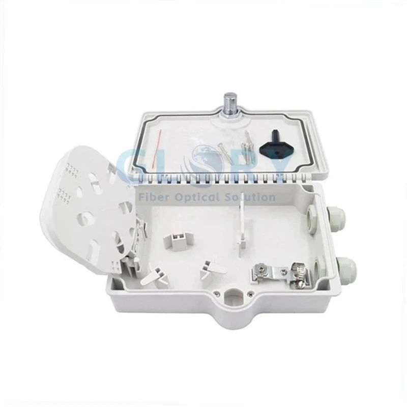
2 Port Fiber Termination Box
Subscriber termination enclosure · Model: GL-FTB-4F
- Two adapter positions
- Splicing and storage for up to four fibers
- Internal bend radius listed as greater than 30 mm
Evaluate this enclosure when a low-count handoff needs organized splicing, slack storage and presented ports. The open product view helps assess the routing arrangement.
Before ordering: Confirm cable-entry fit, adapter format, polish and whether pigtails are supplied; approve the loaded route before ordering.

SC APC To SC APC Simplex OS2 Fiber Patch Cable
Wall outlet to ONT jumper · G.657.A1 · SC/APC to SC/APC · simplex OS2
- G.657.A1 fiber
- 2.0 mm cable diameter listed
- Cable bend limits: 10D dynamic / 5D static
Consider this jumper for an indoor connection where both ports require SC/APC. Its separate fiber and cable specifications make it a useful choice to evaluate against the final equipment route.
Before ordering: Check both port interfaces, required length, boot clearance and the jacket specification for the installation.
For a complete subscriber connection, specify the drop, termination enclosure, adapter/pigtail arrangement and ONT jumper as separate line items. Check the interfaces together; product photographs illustrate listed products and do not define the supplied loading or accessories.
What should an RFQ and sample approval package include?
A useful request for quotation specifies the connection and acceptance requirements alongside the fiber grade. Provide enough information for suppliers to quote the same configuration and for installers to evaluate the same sample.
| RFQ field | Information to provide |
|---|---|
| Route and environment | Indoor/outdoor segments, installation method, tightest route constraint and enclosure drawing |
| Fiber specification | Category, standard edition, manufacturer/reference if required, and existing fiber to be joined |
| Cable or assembly | Fiber count, diameter, jacket requirement, lengths, connector type/polish and buffer construction |
| Mechanical requirements | Installation and static bend limits, pulling conditions, clamps and strain relief |
| Optical acceptance | Operating/test wavelengths, connector criteria, splice criteria and overall link budget |
| Evidence | Approved datasheet, sample identification, relevant test reports and traceability requirements |
| Commercial requirements | Quantity, packaging, destination, requested delivery date and substitution approval process |
Before approving a production order, review the sample in the intended hardware and retain the agreed configuration and acceptance records. Confirm current availability, lead time and any required compliance documentation for the exact item being ordered.
Send Glory Optical your fiber selection and assembly requirements, including the existing fiber type, route drawing and required connectors. Request a quotation against that specification so the proposed cable, pigtail, jumper and enclosure can be reviewed as one connected design.