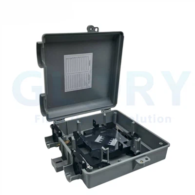
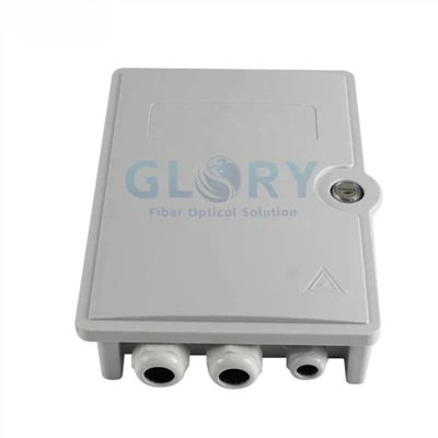
Product overview
A Compact FTTH Termination and Subscriber Handoff Point
The GL-FTB-4F combines cable entry, fiber splicing, slack storage and adapter presentation in one enclosure. It is intended for low-count access nodes where an outside cable must be transitioned to customer-side cabling without using a larger distribution box.
Core Enclosure Configuration
The GL-FTB-4F provides two SC or LC adapter positions, capacity for splicing and storing up to four fibers, an internal fusion-splice tray, cable entry for Ø3–13.5 mm cable and wall- or pole-mount installation. Its IP65 housing supports indoor and outdoor FTTH termination points.
What Must Be Defined per Order
Adapter format, UPC or APC polish, splitter loading, pigtail length, cable construction, exact gland allocation, mounting accessories, lock arrangement, labels and packaging must be confirmed in the approved BOM. Optional fields are not treated as standard loaded content.
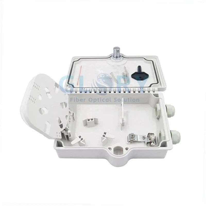
Open enclosure with hinged splice tray, gasketed cover and cable-management area.

Internal routing view before adapters, pigtails or an optional micro PLC splitter are loaded.

Mounting-hole center spacing: 110 mm horizontally and 175.5 mm vertically.
Capacity is not the same as port count
The box has two adapter positions but can splice and store up to four fibers. LC duplex adapters can present more connector channels than two SC simplex adapters, so the connector count, active-fiber count and internal splice schedule must be stated separately in the project drawing.
Product selling points
Technical Advantages of the GL-FTB-4F 2 Port Fiber Termination Box
Each point below connects a technical feature to a practical selection or installation decision.
Two Presented Ports, Four-Fiber Management
Two adapter positions accept SC simplex or LC duplex formats, while the tray accommodates splicing and storage for up to four fibers. Separating presented ports from internal fiber capacity prevents an underspecified splice plan and lets buyers match the enclosure to a one- or two-subscriber handoff.
IP65 Indoor/Outdoor Housing
The UV-resistant engineering-plastic enclosure has an IP65 rating and a −40°C to +85°C operating range. Compared with an indoor wall outlet, the sealed housing provides a defined dust and water-jet barrier for exterior walls or poles; IP65 does not indicate continuous submersion.
Ø3–13.5 mm Cable Entry Range
The Ø3–13.5 mm cable-entry range covers outdoor cable or indoor drop cable. This gives project teams one compact housing for several feeder or drop constructions, provided each actual cable outside diameter, gland allocation and sealing part is checked before the BOM is released.
Controlled Internal Fiber Routing
A hinged fusion-splice tray separates splice protection and fiber storage from the lower cable-entry area. The page specifies an internal bend radius greater than 30 mm, helping installers route pigtails and stored fiber without forcing tight turns; the final route should follow the approved fiber map.
SC/LC and UPC/APC Interface Choices
The adapter field supports SC simplex or LC duplex, with UPC as the default polish and APC available. Insertion loss including the adapter is specified at ≤0.2 dB, with return loss of ≥50 dB for UPC or ≥60 dB for APC; scope and test method should be confirmed for the ordered assembly.
Optional Splitter and Pre-Termination
The enclosure can be ordered with a 1×2 or 1×4 micro PLC splitter, pre-installed connectors and specified pigtails. Factory loading converts separate field components into a controlled assembly, but the splitter ratio, connector polish, pigtail length, port map and optical report remain order-specific rather than standard.
Product family and options
GL-FTB-4F Configuration Paths
The GL-FTB-4F is one enclosure model with several loading options. These options should be selected as mutually compatible BOM fields, not treated as one universal default configuration.
Splice-and-Patch Terminal
Use the housing with two selected SC simplex or LC duplex adapters and the required pigtails. State UPC or APC polish, active-fiber count, pigtail length and the splice-to-port schedule.
Micro PLC Splitter Terminal
Add one 1×2 or 1×4 micro PLC splitter when the node must divide a PON feed. Confirm the actual splitter package, input/output termination, connectorization, wavelength requirements and worst-port loss in the approved splitter datasheet.
OEM Loaded Assembly
Specify pre-installed connectors, pigtails, optional splitter, housing identification and packaging artwork. A controlled sample or drawing should define exactly which components are factory fitted and which work remains for field installation.
Product specifications
2 Port Fiber Termination Box Technical Specifications
The tables below organize the GL-FTB-4F enclosure, capacity, optical interface and configuration data for project selection. Order-specific optical component limits and test conditions should be frozen in the quotation, drawing and BOM.
General Technical Specifications
| Parameter | Specification | Procurement Interpretation |
|---|---|---|
| Product model | GL-FTB-4F (NID) | Use this model on drawings, labels and BOM revisions. |
| Product family | Outdoor/indoor fiber termination box | Low-count FTTH termination and network-interface application. |
| Adapter port count | 2 positions | SC simplex or LC duplex; do not equate positions with fiber capacity. |
| Fiber capacity | Up to 4 fibers | Capacity for splicing and internal storage. |
| Dimensions | 208 × 153 × 52 mm (L × W × H) | Confirm enclosure clearance and cable-bend space at the installation point. |
| Weight | Approx. 0.5 kg, empty | Loaded weight depends on the selected adapters, pigtails and splitter. |
| Enclosure material | UV-resistant engineering plastic | The exact resin grade is not identified on the page. |
| Protection rating | IP65 | Dust-tight and resistant to water jets; not a submersible rating. |
| Operating temperature | −40°C to +85°C | Operating range for the enclosure. |
| Storage temperature | −40°C to +85°C | Storage range for the enclosure. |
| Mounting method | Wall or pole mounting | Confirm the required bracket, fasteners and site orientation. |
| Minimum internal bend radius | >30 mm | Apply to the tray routing plan and stored-fiber path. |
| Locking | Mechanical lock or padlock provision | Confirm the required access-control arrangement. |
| Flame rating | UL94 V-0 optional | Optional requirement; confirm material evidence for the ordered housing. |
| Impact test reference | IEC 60068-2-27 | Project testing can be specified according to agreed conditions and report scope. |
| Vibration test reference | IEC 60068-2-6 | Project testing can be specified according to agreed conditions and report scope. |
Model and Capacity Table
| Model | Fiber Capacity | Adapter Positions | Adapter Format | Splitter Space | Dimensions |
|---|---|---|---|---|---|
| GL-FTB-4F (NID) | Up to 4 fibers for splicing and storage | 2 | SC simplex or LC duplex | Optional 1×2 or 1×4 micro PLC | 208 × 153 × 52 mm |
Optical Interface Specifications
| Parameter | Specification | Boundary to Confirm |
|---|---|---|
| Connector interface | SC simplex or LC duplex adapters | Adapter and mating connector must use the ordered format. |
| Polish type | UPC default; APC optional | Keep polish consistent across adapter, pigtail and connecting cord. |
| Insertion loss | ≤0.2 dB, including adapter | Confirm whether the limit applies per mated pair or to the complete loaded path, then state the test reference in the order. |
| Return loss | UPC ≥50 dB; APC ≥60 dB | Apply to the corresponding ordered polish and define the tested component/path. |
Optical values require a defined test boundary
The enclosure itself is passive mechanical hardware. Insertion-loss and return-loss limits relate to the fitted connectorized path, so the purchase specification should define whether the ≤0.2 dB limit applies to one mated adapter pair or the complete pre-terminated assembly. Add the agreed reference plane, wavelength and report format to the order.
Splitter Configuration Table
| Configuration | Input | Outputs | Availability | Order Fields to Confirm |
|---|---|---|---|---|
| 1×2 micro PLC splitter | 1 | 2 | Optional housing configuration | Package dimensions, fiber type, connectorization, polish, wavelength, loss limits and port map. |
| 1×4 micro PLC splitter | 1 | 4 | Optional housing configuration | Package dimensions, fiber type, connectorization, polish, wavelength, loss limits and port map. |
Splitter insertion loss, uniformity, PDL, directivity, operating wavelength and part number depend on the selected PLC component and must be defined in the order-specific splitter specification.
Cable and Connector Compatibility
| Item | Compatibility | Pre-Order Check |
|---|---|---|
| Cable type | Outdoor cable or indoor drop cable | Confirm construction, jacket, strength member and route environment. |
| Cable outside diameter | Ø3–13.5 mm | Match every cable OD to the actual gland or knockout in the approved entry map. |
| Adapter interface | SC simplex or LC duplex | State adapter quantity, color, sleeve type and mating connector. |
| Polish | UPC default; APC optional | State one compatible polish for adapters, pigtails and connecting cords. |
| Pigtails | Factory pre-installation available | Specify fiber type, jacket diameter, length, color sequence, connector and optical test limits. |
| Sealing structure | Cable glands/knockouts shown and described on the page | Confirm entry count, OD range and unused-port closure against the final drawing. |
Network-node selection
2 Port Fiber Termination Box Applications for FTTH and Access Networks
Use the GL-FTB-4F where the required port count, splice schedule, cable entry and environmental rating fit this specific enclosure.
Outdoor FTTH Subscriber Handoff
An indoor wall outlet does not provide a defined exterior dust and water-jet barrier, while a large distribution box adds unused capacity at a single-home handoff. The GL-FTB-4F uses an IP65 housing, two adapter positions and four-fiber splice/storage capacity at an exterior wall or pole between the provider cable and subscriber drop. It accepts Ø3–13.5 mm cable and SC simplex or LC duplex interfaces. Before purchase, confirm cable OD, UPC/APC polish, active-fiber count, mounting hardware, gland allocation and whether adapters and pigtails arrive factory fitted.
Small Office or Commercial Access Point
Leaving splices and patch connections in separate unprotected fixtures complicates labeling and fault isolation at a small business demarcation point. This compact NID places the splice tray, stored fiber and two presented adapter positions inside one lockable enclosure, installed on an internal or external wall or on a pole near the service entrance. SC simplex supports a conventional presented interface, while LC duplex can increase connector density within the listed positions. Procurement should define the circuit count, connector/polish, pigtail schedule, cable OD, port labels and optical acceptance boundary.
MDU Floor or Unit-Level Fiber Termination
Using a two-port terminal as the main distribution point for a high-density MDU would constrain expansion and confuse port capacity with subscriber count. The GL-FTB-4F is better positioned at a floor, riser branch or individual unit handoff where no more than two adapter positions and four managed fibers are required. The box can transition an approved Ø3–13.5 mm riser or drop cable to SC or LC connections. Buyers should verify fire-rating requirements for the building route, mounting location, fiber map, lock access and whether a higher-capacity distribution box is needed upstream.
GPON or XGS-PON Split-and-Terminate Node
A bare splitter left beside separate adapters creates an undefined fiber route and makes the delivered BOM difficult to repeat. The GL-FTB-4F can house an optional 1×2 or 1×4 micro PLC splitter with connector and pigtail loading, forming a compact split-and-terminate point at a wall- or pole-mounted access node. It can connect the incoming PON fiber to the required SC or LC outputs, but the enclosure does not determine optical budget. Confirm splitter package, ratio, wavelength, actual worst-port loss, connector polish, output map and test report before approval.
Ordering configuration
RFQ Fields for a Custom 2 Port Fiber Termination Box
Send these fields together so the quotation describes one reproducible GL-FTB-4F assembly rather than a housing name alone.
| Order Field | Option or Range | Information Required from Buyer |
|---|---|---|
| Model | GL-FTB-4F (NID) | Model name and drawing/BOM revision. |
| Housing loading | Enclosure with project-selected internal configuration | Unloaded or factory-loaded; list every supplied component. |
| Adapter ports | 2 positions | SC simplex or LC duplex; quantity and sleeve requirement. |
| Connector polish | UPC default; APC optional | Required polish and mating connector at each port. |
| Fiber schedule | Up to 4 fibers | Feeder/drop fiber count, color map, splice map and active/spare status. |
| PLC splitter | Optional 1×2 or 1×4 micro type | Ratio, package, fiber type, input/output termination and optical limits. |
| Pigtails | Factory pre-installation available | Fiber type, connector, polish, length, jacket diameter, colors and test values. |
| Cable entry | Ø3–13.5 mm cable range | Every cable type, construction, actual OD, entry position and sealing requirement. |
| Mounting | Wall or pole | Mounting location, bracket/fastener requirement, orientation and working clearance. |
| Access control | Mechanical lock or padlock provision | Required lock arrangement and key/access responsibility. |
| Identification | Logo/model printing offered | Approved artwork, enclosure label, port numbering, cable tags and lot-code format. |
| Packaging | Customer printing offered | Neutral or OEM carton artwork, unit label, accessory pack and packing-list fields. |
| Documents and testing | Project-defined | Approved drawing, BOM, optical report, dimensional/assembly checks and requested material evidence. |
Recommended RFQ line
GL-FTB-4F indoor/outdoor 2 port fiber termination box, IP65, 208 × 153 × 52 mm, wall/pole mount [select], two [SC simplex / LC duplex] adapter positions, [UPC / APC], [unloaded / adapters and pigtails / 1×2 micro PLC / 1×4 micro PLC], cable [type and OD], entry map [revision], fiber/port map [revision], lock [type], mounting accessories [list], labels [artwork], optical test boundary and report [define], packaging [define].
OEM and project configuration
Control the Loaded Terminal Through One Approved BOM
Glory Optical lists pre-installed connectors, pigtails, micro PLC splitters, housing identification and packaging printing for this model. Project configuration should move through drawing and sample confirmation before repeat production.
Drawing and Port-Map Review
Confirm enclosure dimensions, mounting pattern, entry allocation, adapter positions, tray route, splitter location and port labels in one drawing revision.
Loaded Optical Assembly
Define adapters, pigtails and optional PLC splitter by part description, fiber type, connector polish, length, color sequence and optical acceptance record.
Identification and Packing
Approve housing print, model label, port numbering, carton artwork, accessory list and packing-list format so repeat shipments use the same identification system.
Suggested project release sequence
Application data → configuration drawing → project BOM → sample confirmation → optical and assembly checks → label/packing approval → batch production.
Company background
Why Glory Optical for GL-FTB-4F Project Supply
Glory Optical Communication is a Ningbo-based passive fiber optic infrastructure manufacturer founded in 2008. Its official company profile lists a 20,000 m² manufacturing facility, more than 300 passive optical products, service to more than 50 countries and OEM/ODM project support.
Housing and Terminal Assembly
For fiber boxes, the company profile identifies mold and CNC capability, enclosure assembly, adapter and pigtail loading, splice-tray assembly and port-map control. These capabilities are directly relevant when the GL-FTB-4F changes from an unloaded enclosure to a project-specific terminal.
Testing and Production Control
Connectorized products can be checked for insertion loss, return loss and end-face condition where applicable. The production workflow also includes incoming-material inspection, dimensional checks, assembly review, port-configuration confirmation and packing inspection.
OEM/ODM Configuration
OEM/ODM support can include housing structure, port layout, cable entry, color, logo, labels, packaging, adapter configuration, cable length, splitter integration and splice-tray layout. Only the fields confirmed in the approved drawing and BOM apply to a specific order.
Sample and Repeat-Order Control
A practical supply path is to approve a drawing or sample, record the optical component list and test scope, then lock labels and packaging into the project BOM. This gives procurement a repeatable reference for later batches.
Learn more about Glory Optical's manufacturing workflow and company capabilities on the About Us page. The approved GL-FTB-4F drawing and BOM remain the controlling documents for each order.
Build an orderable GL-FTB-4F BOM
Specify the 2 Port Fiber Termination Box Around Your Actual Fiber Path
Send the cable type and OD, mounting location, adapter format, UPC/APC polish, active-fiber and splice map, optional splitter, pigtail schedule, lock, labels, test scope and packaging requirements. Glory Optical can review these fields against the GL-FTB-4F configuration before quotation.
Hot Tags: 2 port fiber termination box, China 2 port fiber termination box manufacturers, suppliers, factory, Outdoor Fiber Optic Junction Box, Nid Box, fiber optic box outdoor, Optical Fiber Distribution Box, fiber outlet box, box fiber