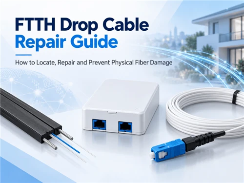
A repaired FTTH drop is not finished when the ONT comes back online. Long-term reliability also depends on cable retention, strength-member anchoring, enclosure selection, route protection and post-repair verification.
A KPN community post dated September 13, 2026 illustrates the distinction. The user reported that a residential fibre cable had previously been damaged during street excavation and repaired using what the user called a "fixing box." During later electrical work in the street, the fibre failed again, and the user observed that one cable end had come out of the box.
The discussion did not establish whether the cause was external pulling force, cable retention, enclosure installation, route protection or another factor. The useful engineering question is therefore not whether that particular enclosure was defective. It is whether a repaired FTTH drop has both a working optical path and a controlled mechanical load path.
What Makes an FTTH Drop Repair Complete?
A finished repair has two acceptance conditions. The optical condition confirms that the repaired path meets the network's test requirements. The mechanical condition confirms that the cable structure, closure and route protect the splice from the loads expected in service.
ITU-T L.400/L.12 (02/2022), Optical fibre splices, describes splices as critical points that affect both link quality and lifetime and states that their performance should remain stable under the expected environmental conditions of the link.
Optical path
Confirms that the repaired optical path meets the operator's test requirements.
Mechanical load path
Controls pulling and movement before those loads reach stripped fibre or the splice protector.
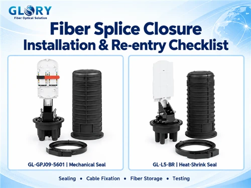
For a detailed general procedure covering closure installation, sealing, re-entry and tray management, see Glory Optical's Fiber Splice Closure Installation & Re-entry Checklist. That guide covers closure workmanship in depth; this article focuses specifically on the repair point created after an FTTH drop has been damaged.
Repair the Drop or Replace It?
A localised break in otherwise healthy cable can often be considered for fusion-splice repair where sufficient slack is available, the operator permits a permanent splice, and an appropriate enclosure can restrain and seal both cable ends. Replacement deserves stronger consideration when mechanical damage extends beyond a clearly defined break.
| Field condition | Repair may be reasonable | Replacement or rerouting deserves stronger consideration |
|---|---|---|
| Damage extent | Localised and clearly bounded | Long section crushed, stretched, stripped or uncertain |
| Cable condition | Jacket and load-bearing elements remain sound | Structural damage extends away from the visible break |
| Available slack | Enough healthy cable for approved preparation | Cable must be tensioned simply to reach the closure |
| Closure compatibility | Correct entry, seal and retention arrangement available | Cable cannot be secured correctly |
| Route exposure | Repair location can be protected | Same point remains exposed to excavation or pulling |
| Operator practice | Permanent field splice permitted | Subscriber-drop replacement required by procedure |
| Future maintenance | Repair remains identifiable and accessible | Added closure creates unnecessary complexity |
Pre-terminated or pre-connectorized subscriber drops add another consideration. If the complete route is short and accessible, replacing the drop can sometimes avoid creating an additional permanent splice point. If replacement would require substantial civil work or route reconstruction, a properly engineered repair may be the more practical option. This remains an operator- and project-specific decision.
ITU-T L.105 (11/2025), Optical fibre cables for drop applications, states that the characteristics and detailed evaluation conditions of a drop cable depend on the environment in which it will be installed. Corrigendum 1, approved in August 2026, restores descriptions covering ageing, longitudinal water penetration, moisture permeation, and rodent or insect damage.
The procurement implication is important: repairing the glass does not correct an unsuitable cable construction or an unsuitable route. Glory Optical discusses this distinction in its ITU-T L.105 Drop Cable RFQ Guide.
How to Select a Splice Closure for an FTTH Drop Repair
A repair closure should be selected from the cable and installation environment outward. Starting with "24-core," "72-core" or "IP68" misses several variables that determine whether the repaired cable can actually be retained and sealed.
Cable size and profile
Confirm the actual cable dimensions at the intended sealing position. A flat 2 × 3 mm FTTH drop, a small round subscriber cable and a larger loose-tube distribution cable do not automatically use the same entry arrangement. A nominal port diameter is not proof that a particular flat or round cable can be sealed and restrained correctly.
Cable construction and strength members
Identify which part of the cable is intended to carry tensile load. Depending on the design, this can include FRP members, steel wires, aramid yarn, a messenger or another reinforcement system. The closure needs a compatible way to secure those structural elements. Cable OD alone does not answer this question.
Cable-entry requirement
Count the physical cable directions rather than looking only at fibre count. A point-to-point repair may need two cable directions, while a damaged distribution section can require additional branch ports, express-cable management or future access capacity.
Splice and tray capacity
Capacity should fit the repair rather than dominate the selection. A single subscriber fibre does not automatically justify a large OSP closure. Conversely, a distribution cable serving several drops may need additional trays, branch space and organised fibre storage.
Installation environment
"Outdoor" is too broad to be a complete specification. IEC 61753-1:2018 defines performance environments for passive fibre-optic components. Specific sealed-closure standards include Category A for aerial, Category G for ground-level, and Category S for subterranean applications.
Re-entry requirement
A repair point can become a future maintenance point. IEC 61300-2-33:2026, Edition 4, includes procedures related to protective housings after repeated assembly and disassembly and evaluates sealing performance after repeated opening and closing.
Glory Optical product context
Glory Optical's Fiber Optic Enclosure range includes dome, inline and multi-purpose splice enclosures for different outdoor network configurations.
GL-GPJ09-9417-B - product-fit example
The GL-GPJ09-9417-B Splice Closure for Optical Fiber Cable publicly lists three inlet and three outlet ports, support for Φ3 mm and Φ8–20 mm cables, IP68 protection and up to 72 fibre splices.
Selection caution: these specifications show the parameters that need to be compared. They do not establish compatibility with every 3 mm or 2 × 3 mm FTTH drop construction, and they do not mean a 72-core enclosure should automatically be selected for a one-fibre residential repair.

GL-GPJ09-9417-B - Product View

Closure Structure Detail

Repair-Specific Installation Checks
The general closure installation guide explains the complete workflow. At a repair point, four checks deserve particular attention because they determine whether the new joint becomes a mechanical weak point.
1. Define the healthy cable boundary
Do not assume the visible glass break marks the complete damage zone. Inspect the cable on both sides for stretching, crushing, flattening, jacket damage or disturbed strength members. The repair should start and finish in cable that remains structurally suitable for service according to the approved repair procedure.
2. Secure the cable structure before relying on the fibre
The jacket and designated strength members should engage with the enclosure's retention system before the internal fibre path is treated as complete.
FOA's splice-closure guidance notes that cable preparation should follow the manufacturer's specified sequence so the cable is properly secured, adequate strain relief is established and the closure can seal correctly. It also notes that different jacket and strength-member designs may require specific hardware.
ITU-T L.201/L.13 (05/2021), Performance requirements for passive optical nodes: Sealed closures for outdoor environments, likewise includes cable attachment and termination in its performance framework.
3. Prepare and seal the actual cable entry
Use the strip lengths, strength-member preparation, sealing elements and assembly sequence specified for the actual closure and cable combination. Generic dimensions copied from another model can interfere with clamp engagement, gasket compression or heat-shrink positioning.
G.657 bend-insensitive fibre also does not override the limits of the finished drop cable. Fibre grade describes the optical fibre; the finished cable still has its own jacket, reinforcement, connector boot and installation limits. Glory's Fiber Optic Bend Radius Guide discusses this distinction in more detail.
4. Support the repaired section and surrounding route
The enclosure should be mounted or stored according to its intended deployment method, with enough supported cable that the entry ports do not become the only points resisting cable movement. This is especially important after a civil-work incident.
Repair the Route, Not Only the Joint
The KPN case is useful because the second outage occurred during later street work, but the public discussion does not establish why the cable came out of the repair box. The appropriate lesson is therefore to inspect the repaired location as a system.
Underground
Check whether excavation, duct movement, cable pulling or handhole activity can transfer load into the repair point.
Aerial
Inspect drop clamps, service loops, closure support and the transition toward the building.
Wall-mounted
Support the cable on both sides so that enclosure entries do not become anchor points.
Duct route
Keep enough space and protection that future cable installation work will not pull directly against the closure.
Post-Repair Acceptance
Final acceptance should cover the optical path, mechanical condition and maintenance record.
Optical condition
Test the repaired path using the operator's approved method and acceptance criteria. ITU-T L.400/L.12 covers fibre-splice performance, but a single universal field loss limit should not be imposed across every FTTH network or operator.
Where required, retain OTDR traces and end-to-end power or OLTS results so the repair establishes a new baseline. Glory Optical has published an anonymized ISP maintenance case in which mechanically damaged cable remained optically continuous on some fibres while introducing severe additional attenuation. That case is not an FTTH drop-repair case, but it demonstrates why "not completely broken" and "acceptable optical condition" are different conclusions. See Fiber Optic Cable High Loss but Not Broken: OTDR Case.
Mechanical condition
Verify that cable-retention hardware is engaged, required strength members are anchored, fibres are clear of pinch points, the enclosure is supported correctly, cable slack follows the permitted bend path and external movement is not transferred directly to the splice area.
Repair record
The handover record should allow another technician to understand what was repaired without reconstructing the job from memory. Useful records include the repair location, closure or asset ID, cable and fibre identification, splice assignment, optical results, repair date and relevant route photographs or drawings.
10-Point FTTH Drop Cable Repair Checklist
Use this final check after the repair work is complete:
| Check | Acceptance question |
|---|---|
| 1. Damage boundary | Has damaged or questionable cable been removed or excluded from the repaired section? |
| 2. Cable condition | Are the jacket and load-bearing elements sound on both sides? |
| 3. Closure compatibility | Does the entry arrangement match the actual cable size, profile and construction? |
| 4. Cable retention | Are the jacket and required strength members secured by the intended hardware? |
| 5. Splice isolation | Is external tensile load kept away from bare fibre and the fusion splice? |
| 6. Fibre routing | Does stored fibre follow the approved tray and cable bend requirements? |
| 7. Entry sealing | Were the correct sealing parts and preparation procedure used? |
| 8. Closure support | Is the enclosure mounted or supported as intended rather than hanging from the fibre cable? |
| 9. Route protection | Has the original excavation, pulling, crushing or movement risk been addressed? |
| 10. Handover | Are optical results, location, identification and repair records complete? |
What to Include in a Repair-Closure RFQ
A useful RFQ describes the cable and field environment rather than asking only for "an IP68 splice box."
| RFQ input | Why it matters |
|---|---|
| Cable outer dimensions and profile | Determines entry and sealing compatibility |
| Cable construction | Identifies suitable cable-restraint approach |
| Strength-member type | Determines mechanical anchoring |
| Number of cable entries/exits | Defines physical port requirements |
| Fibre and splice count | Defines tray capacity |
| Installation environment | Distinguishes aerial, wall, duct, handhole, ground or subterranean deployment |
| Mounting method | Identifies support and accessory requirements |
| Re-entry requirement | Affects maintenance and sealing strategy |
| Route photo or drawing | Reveals space and mechanical constraints |
| Operator/project requirement | Defines applicable documentation and qualification evidence |
Frequently Asked Questions
Can a broken FTTH drop cable be repaired by fusion splicing?
Yes. A localised break can often be fusion-spliced where the remaining cable is structurally healthy, sufficient slack is available, the operator permits a permanent splice and the selected enclosure can correctly restrain and seal both cable ends. Replacement becomes more attractive when mechanical damage extends beyond the visible break.
Does IP68 automatically make a splice closure suitable for an underground repair?
No. Ingress protection is only one specification. Cable-entry compatibility, retention, installation environment, sealing system, mounting method and the relevant project requirements still need to match the repair.
Should the fusion splice carry cable tension?
No. External mechanical load should be transferred through the cable's structural elements and the enclosure's intended retention hardware. The fusion splice and bare fibres are part of the optical path, not the cable's primary load-bearing system.
Conclusion
A durable FTTH drop repair is not defined only by whether service returns. It also depends on whether the damaged cable has been reduced to a healthy repair boundary, the selected closure matches the real cable and environment, the load-bearing structure is restrained, the repaired route is protected, and the finished link is tested and documented.