This guide focuses exclusively on re-entry and retrofit decisions. For basic product terminology, installation or port-count guidance, start with Glory Optical's Fiber Optic Termination Box range. The audit below addresses the harder brownfield question: what should happen to a box that is already on the wall or pole?
Fiber Termination Box Re-entry: Can the Existing Box Be Reused?
Yes-provided the box is assessed as a complete installed system. A passive enclosure may remain usable after an OLT change. Reuse ends when the new work exceeds its environmental boundary, connector scheme, fiber-management space or ability to be serviced safely.
This distinction is becoming more important as the installed base matures. The FTTH Council Europe's 2026 Fibre Market Observatory records 295 million FTTH/B homes passed in EU39 and 191 million in EU27+UK as of September 2025. More installed passive nodes now face activation, infill, copper migration and PON-upgrade work, making controlled re-entry an operating issue rather than a future forecast.
The reuse decision should follow the service change
| Planned change | What the audit must prove | Likely outcome |
|---|---|---|
| Add one subscriber | A documented spare port exists; the drop entry fits; live fibers can remain undisturbed. | Retain or make a minor repair. |
| Change GPON electronics to XGS-PON | The passive path, connectors, splitter arrangement and measured optical condition remain compatible. | Usually retain the housing; qualify the optical path. |
| Add a splitter or tray | The approved drawing provides working space, bend control and a defined port map after expansion. | Expand only with a documented kit. |
| Change cable construction | The new sheath diameter, strength member and entry direction can be sealed and strain-relieved. | Repair the entry hardware or replace the box. |
| Move the service boundary | The mounting, ownership demarcation and access rules still make operational sense. | Relocate or replace rather than improvise. |
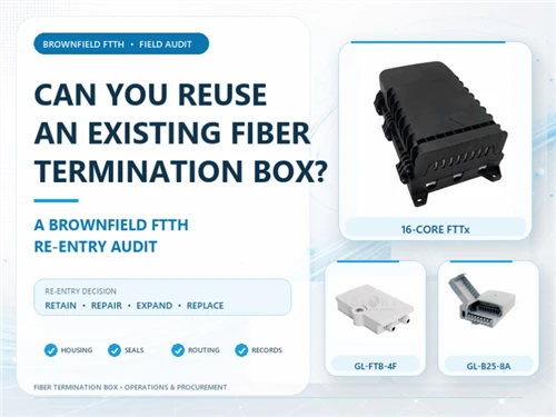
For small subscriber demarcation points, Glory's GL-FTB-4F 2-port Fiber Termination Box illustrates why the cable boundary matters: its published specification defines two adapter positions and a 3–13.5 mm cable-entry range. A retrofit cable outside that range requires a different approved entry solution; additional tightening cannot compensate for incompatible geometry.
Fiber Termination Box Audit: What Should Be Checked First?
Start with a no-touch survey. Photograph the box before loosening a latch, record active services, and compare the visible configuration with the drawing or port database. If the documentation and the enclosure disagree, stop treating unused-looking fibers as spare.
The five-zone re-entry record
The following five-zone record is an original field framework for this article. It turns a subjective "looks fine" inspection into evidence that procurement and operations teams can review together.
- Mounting zone: wall or pole fixing, distortion, impact damage, UV embrittlement, drainage path and safe technician access.
- Lid zone: gasket continuity, compression set, dirty sealing faces, hinge alignment, latch pressure and signs of previous forced entry.
- Cable-boundary zone: occupied and unused ports, actual cable outside diameters, gland or grommet fit, strength-member fixation, entry direction and evidence of water tracking.
- Fiber-work zone: protected splices, tray closures, slack path, connector condition, bend control, separation between feeder, pigtail and drop fibers, and access to the target port without crossing live routes.
- Evidence zone: model and revision, port map, splitter and adapter details, before/after photos, optical baseline, re-entry date and the technician or contractor responsible.
Three documented field accounts and the controls they require
These accounts show how re-entry problems appear in practice. They provide context rather than product-performance evidence, so each lesson is paired with an operator or manufacturer requirement.
Residential FTTP relocation-Australia. In a publicly documented relocation, an existing network termination device had to be moved about 30 meters from an open living area. The project used two pre-terminated armored fiber runs, a two-port wall termination box and connector cleaning before reconnection. The account also records the practical reason for adding the box: it reduced stress on the fiber and provided a controlled handoff beside the relocated equipment. Relocation changes the route, pull protection, termination point and ownership boundary together. The nbn relocation guidance confirms that changes to equipment inside a premises must follow its standards and be completed by an appropriately registered cabler. View the field account.
GPON eco-village distribution-Thailand. A field build documented three 1×4 PLC splitters feeding twelve downstream links. The installer reported that labeling and arranging cable ends consumed roughly 70% of the initial work, then identified strength-member routing and entry fixation as areas that would be changed on the next box. The optical path worked, while maintainability still depended on a reliable port map, protected 250 µm fiber and strain relief that ends at the entry zone. Openreach's current New Sites Fibre Handbook reinforces the control principle by treating protected and sealed cable or tubing in a joint box as a quality-check item. View the field account.
Outdoor enclosure water ingress-field maintenance. A telecom field report describes rain-filled handholes and improperly sealed underground and aerial joints as recurring operational conditions. Replacing a wet pigtail alone leaves an incompatible gland, unsealed duct or damaged closure boundary unresolved. Corning's generic specification for optical fiber splice closures explicitly includes re-entry and reassembly during environmental cycling, followed by water-intrusion checks. That sequence supports the practical audit rule: trace the water path, restore the complete entry-and-seal system, and then verify it. View the field account.
When the box passes the no-touch survey, use Glory's existing Fiber Optic Termination Box installation guide for the detailed access, cleaning, splicing and testing workflow. Keeping those steps in the installation page prevents this re-entry article from competing with it.
Fiber Termination Box Sealing: Does IP65/IP68 Survive Re-entry?
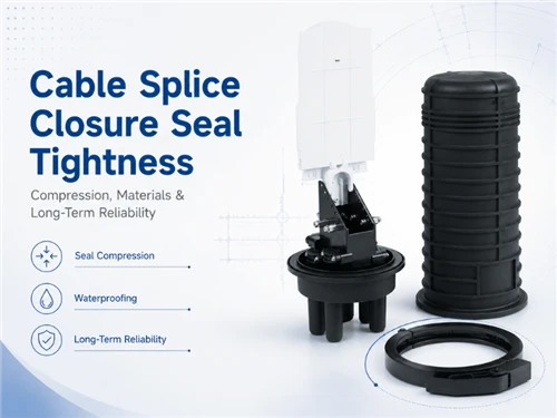
An IP label describes the tested enclosure configuration. Every later cable, gland, plug and closing event must preserve that configuration's sealing logic. IEC 60529 defines the IP Code, while IEC 61753-101-03 specifies minimum tests and measurement requirements for fiber-management systems in an outdoor protected environment. Field sealing still depends on compatible entries and correct reassembly.
Five sealing points to re-qualify
- Perimeter gasket: continuous, clean, correctly seated and free of permanent flattening, stretching or cuts.
- Occupied cable entries: the sealing part matches the measured cable rather than its nominal family, and the sheath remains round and undamaged.
- Unused entries: the specified plugs are present; the tested closure system takes precedence over tape, putty or improvised foam.
- Latch or fastener pattern: the lid closes evenly without a fiber, label or strength member crossing the sealing line.
- Mounting and drainage: the enclosure remains unwarped on its mounting surface, and cable loops direct water away from every entry.
For buyers who need to distinguish a product test from a factory-system certificate or declaration, Glory's Fiber Box Certifications Explained article provides the correct internal reference. In short: ISO 9001 concerns the quality-management system, RoHS concerns restricted substances, and neither substitutes for enclosure-specific ingress evidence.
Fiber Termination Box Compatibility: Will It Support XGS-PON?
Usually, the passive housing can remain. A Fiber Termination Box manages fibers rather than processing the transmitted data, so PON generation alone does not determine reuse. The installed optical path still needs qualification for connector polish, interface condition, splitters, wavelength-selective components, bend management and its measured baseline.
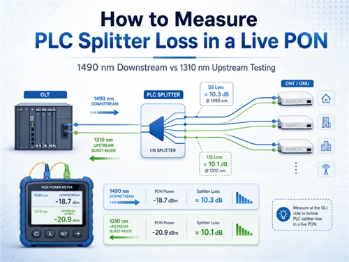
ITU-T G.9807.1 defines XGS-PON and supports coexistence with other PON generations on the same optical distribution network. ITU-T G.657 defines bend-insensitive single-mode fiber used in access and in-building environments. Together, they support qualification of the installed path; readiness for 10G service still requires field evidence.
Check the passive chain in this order
- Identify the fiber and cable construction from reliable records; jacket color alone is insufficient.
- Confirm connector family and polish at both sides of every adapter. An APC/UPC mismatch requires correction rather than cleaning.
- Record splitter ratio, package and lead routing. An undocumented splitter changes the topology and must be included in the audit.
- Inspect, clean and retest interfaces before condemning the housing.
- Save a new optical baseline and tie the file to the corrected port map.
For projects moving beyond XGS-PON, Glory's 50G PON ODN reuse guide owns the network-level audit and optical-budget intent. This article stays at the Fiber Termination Box boundary to avoid competing with that page.
Fiber Termination Box Capacity: Expand Internals or Replace the Housing?
Use the internal drawing rather than the number printed on the cover. Port count, adapter count, splice capacity, splitter outputs and workable tray space are separate purchasing fields. An apparently spare position is usable only if a technician can reach it, route the new fiber, preserve the sealing line and close the lid without compressing another service.
Expansion is justified only when four conditions are true
- The manufacturer or project drawing defines the additional tray, adapter or splitter configuration.
- The required cable enters through a compatible sealed port with proper strain relief.
- The new route preserves fiber bend requirements and leaves existing live paths undisturbed.
- The final port map is readable and can be reconciled with the operator's inventory system.
The 16-Core FTTx Fiber Optic Termination Box is a useful example of specification discipline: its published page separates the main-cable limit, drop-cable geometry, housing environment and project-configured SC/LC or PLC arrangement. Those are the fields a brownfield audit needs. If the existing box cannot reproduce that level of configuration clarity, adding parts may create more uncertainty than usable capacity.
Glory's separate fiber-box capacity guide should continue to rank for general sizing questions. Here, capacity appears only as a retrofit decision: whether the existing working space can accept a documented kit without turning a serviceable box into a packed box.
Fiber Termination Box Decision: Retain, Repair, Expand, or Replace?
The four-way decision below prevents two expensive defaults: replacing every old box because it looks untidy, or retaining every old box because it still passes light.
| Decision | Use it when | Reject this option when | Required record |
|---|---|---|---|
| Retain | Structure, sealing, entries, routing and port map are intact; the target service can be added without disturbing live fibers. | The box only "looks dry" but has no recoverable configuration record. | Photos, verified port map and optical baseline. |
| Repair | Replaceable items such as gasket, plug, gland, adapter or label are defective, while the enclosure geometry remains sound. | The shell, latch line or mounting surface is cracked, warped or no longer closes evenly. | Approved spare-part IDs and post-repair checks. |
| Expand | An approved tray, adapter or splitter kit fits with working clearance, compatible entries and a revised port map. | Expansion depends on tape, loose splitters, crossed routing or undocumented drilling. | Internal drawing, loaded BOM and revised port map. |
| Replace | Sealing cannot be restored; cable geometry cannot be managed; the fiber area is unsafe to re-enter; or traceability cannot be recovered. | A connector only needs cleaning or a replaceable plug is missing. | Before/after migration record and disposal or recovery status. |
A subscriber demarcation box needs a slightly different decision from a shared distribution point. Glory's NID Box guide explains the ownership boundary and distinguishes passive NID hardware from the powered ONT. For a compact indoor or sheltered point, the GL-B25-8A Optical Fiber Termination Box shows a flip-up internal panel and separated routing paths that can simplify later access. Product suitability still depends on the actual approved configuration.
Fiber Termination Box Recommendations After the Re-entry Decision
If the audit ends in replacement or a documented capacity change, choose the new enclosure by service boundary rather than by the largest advertised port count. The three Glory Optical models below address different brownfield outcomes; each image links to the corresponding official product page.

GL-FTB-4F · official Glory Optical product image
GL-FTB-4F 2-Port Box
A compact choice when the audit confirms a small wall- or pole-mounted demarcation point and the incoming cable fits the documented entry range.
- 2 SC or LC adapter positions; up to 4 fibers
- IP65 housing; 208 × 153 × 52 mm
- Published cable-entry range: Ø3–13.5 mm
- Optional 1×2 or 1×4 micro PLC configuration
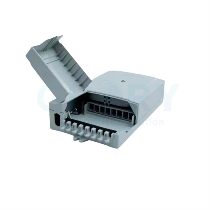
GL-B25-8A · official Glory Optical product image
GL-B25-8A 8-Core Box
A practical fit for indoor or sheltered locations where a compact footprint and clearer access to separated routing zones matter during future re-entry.
- 8-core layout with a flip-up distribution panel
- PC+ABS housing; 235 × 126 × 52 mm
- Published ingress class: IP54
- Position for indoor or sheltered outdoor use
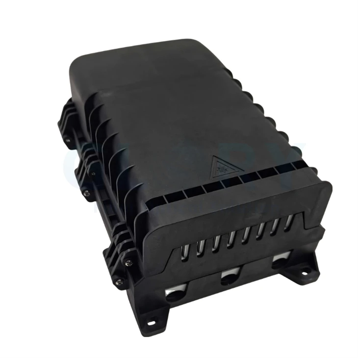
16-Core FTTx model · official Glory Optical product image
16-Core FTTx Box
Use this as the larger-node candidate when the replacement plan needs outdoor protection, multiple mounting options and a project-defined SC/LC or PLC build.
- PP, IP65 housing; 281.4 × 177 × 101.6 mm
- Incoming cable up to Φ12 mm
- 2 × 3 mm drop-cable outlet geometry
- Wall, pole or aerial mounting options
Fiber Termination Box RFQ: What Evidence Should Buyers Request?
A useful retrofit RFQ begins with the existing field condition instead of a request for "the same box with more ports." Send enough evidence for a supplier to reject an unsafe reuse plan before a sample is built.
The re-entry evidence pack
- Exterior, open-box, gasket-line, cable-entry, mounting and internal-routing photographs.
- Known model, drawing revision, installation date and number of previous access events, where available.
- Feeder and drop cable construction, outside diameter, strength member and entry direction.
- Current adapter type and polish, splitter ratio and package, pigtail length, tray use and port map.
- Active, reserved, unknown and physically unavailable positions-kept as four separate statuses.
- Target change: new subscriber, PON upgrade, relocation, splitter change or cable replacement.
- Site exposure: indoor, sheltered outdoor, open wall or pole, high UV, flood risk, dust, vandalism or restricted access.
- Required evidence: model-specific ingress report, material declaration, connector or splitter test data, drawing and sample-approval record.
- Before/after optical results and the required file-naming rule for traceability.
For a standard configuration, compare the evidence pack with Glory's Fiber Termination Box portfolio. If cable entries, internal hardware, labeling or packaging require a project-specific revision, use the OEM/ODM process and ask for an updated drawing before approving a loaded sample. Once the configuration is frozen, submit the drawing, quantities and documentation list through the Glory Optical RFQ form.
Fiber Termination Box FAQs for Brownfield FTTH Projects
Can an existing Fiber Termination Box be reused?
Often yes. Approve reuse only after the housing, seals, cable entries, routing, adapters, splitter arrangement, labels and optical baseline have been checked. Base the decision on condition and evidence rather than age alone.
Does opening an IP65 or IP68 Fiber Termination Box cancel its rating?
The model retains its laboratory classification; however, the reassembled field installation requires verification against the tested state. Recheck the gasket, glands, plugs, cable dimensions and closing pattern, then perform the project-required field acceptance check.
Can an old Fiber Termination Box support XGS-PON?
The passive housing has no inherent speed limit. The installed fiber, connector polish and cleanliness, splitter path, coexistence components, bend management and measured optical condition determine whether the path can be reused.
Should every old pigtail and adapter be replaced during re-entry?
No. Inspect, clean and test before replacing serviceable hardware. Replace components that are physically damaged, repeatedly fail inspection, use the wrong polish, have unknown identity where the project requires traceability, or cannot meet the approved acceptance criteria.
What photographs should be sent to the supplier?
Send the closed exterior, open enclosure, gasket line, all cable entries, internal tray and routing, labels and port map, plus a wider image showing mounting, drainage and technician access. Include a scale or measured dimensions where fit is uncertain.
For step-by-step work after the decision is approved, return to Glory's installation and testing guide. For compliance-document interpretation, use the certification guide. Those pages carry the general installation and documentation intent; this page should remain focused on brownfield re-entry decisions.