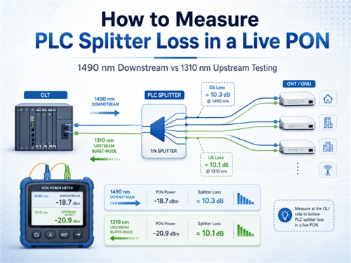
1490 nm
GPON downstream is continuous and is normally the easier in-service measurement.
1310 nm
GPON upstream is burst-mode and requires a compatible wavelength-selective PON power meter.
2 planes
Splitter loss needs a controlled reading before and after the splitter at the same wavelength.
Replacing a healthy splitter because an ONT reports low optical power wastes a truck roll. Accepting a weak branch because a handheld meter shows "pass" can create repeat faults weeks later. Both mistakes begin with the same misunderstanding: optical power measured at one point is being treated as the insertion loss of one component.
- One reading is optical power at a test point.
- Splitter loss requires two controlled measurements.
- Both readings need the same wavelength, propagation direction and clearly defined reference planes.
- GPON downstream at 1490 nm is continuous; upstream at 1310 nm is burst-mode.
- Upstream testing therefore needs a burst-capable, wavelength-selective PON power meter.
If adapters, jumpers, connectors or nearby splices lie between the two reference planes, the result is the installed path loss across those planes. It is not automatically the bare PLC chip or factory component value.
Define the two reference planes before testing. Any connection or splice between them becomes part of the reported installed loss.

What Does a Live PON Power Reading Actually Tell You?
An ONT diagnostic value reflects the whole optical distribution network between the active equipment and that receiver. Feeder fiber, splices, connectors, splitter stages, drop cable, contamination and measurement tolerance can all influence the result. It does not isolate the PLC splitter.
| Measurement | What it establishes | What it does not establish by itself |
|---|---|---|
| ONT-reported receive power | Approximate received power at the ONT receiver | The standalone insertion loss of the PLC splitter |
| Pass-through PON meter at the ONT | Wavelength-selective power at that field point | Where earlier loss occurred in the ODN |
| Readings before and after the splitter | Installed loss between two declared reference planes | Bare-component loss if connectors or splices are included |
Representative field case: A weak ONT value was initially assigned to the splitter. Replacing the splitter produced almost no change. Inspection later found a contaminated connector and an additional repair splice in the drop path. The original reading described the complete path; it never proved the splitter was defective.
The Fiber Optic Association's insertion-loss guidance reinforces the basic principle: loss is determined between defined points with a controlled source and measurement method. For network context, see how fiber splitters work and how splitters sit inside an FTTH optical distribution network.
What Equipment Is Needed for Live PLC Splitter Loss Testing?
For an in-service PON, the primary field instrument should be a calibrated, wavelength-selective pass-through PON power meter. It should separate the applicable downstream and upstream bands, pass traffic while connected, and capture burst-mode upstream power for the PON generation under test.
PON power meter
Use for live, wavelength-selective measurements. Confirm supported bands, burst-mode capability, pass-through direction, dynamic range, connector type and calibration status.
Conventional optical power meter
May be useful for a simple continuous downstream check on GPON, but it cannot reliably separate mixed wavelengths or characterize time-division upstream bursts.
OTDR
Use to locate reflective events, splices, bends and distance-related faults. It answers a different question and does not replace controlled power measurements across a splitter.
Inspection and cleaning kit
Include a fiber inspection scope, approved cleaners, known-good test jumpers and the correct APC or UPC adapters. Cleanliness is part of the measurement system.

A practical equipment specification should reference the applicable performance framework, such as IEC 61315 calibration requirements for optical power meters, and the meter manufacturer's instructions for live PON operation. Before connecting, follow a repeatable fiber connector inspection and cleaning process.
How Do You Measure Downstream PLC Splitter Loss at 1490 nm?
GPON downstream at 1490 nm is continuous, so it is usually the most stable starting point for live loss assessment. The goal is to compare the splitter input with one selected output under the same network state.

1. Confirm the PON technology
Verify that the network is GPON and that 1490 nm is the intended downstream band. A coexistence network may also carry video, XGS-PON or other wavelengths, so do not rely on a broadband power reading that combines them.
2. Define both reference planes
Document the exact input-side and output-side connection points. State whether adapters, pigtails, jumpers or splices are included. Without this definition, a later technician cannot reproduce or interpret the loss value.
3. Inspect every interface you will disturb
Inspect before connecting, clean when necessary, and inspect again. Match APC to APC and UPC to UPC. A contaminated or mismatched test interface can add more uncertainty than the splitter variation being investigated.
4. Measure the splitter input
Connect the PON power meter in the correct pass-through orientation at the declared input reference plane. Allow the reading to stabilize and record the 1490 nm value, meter identity, jumper arrangement and time.
5. Measure the selected output
Move to the chosen output reference plane, preserve the same wavelength and meter configuration, and record the 1490 nm power. Identify the exact splitter port; port-to-port uniformity means one branch cannot represent every output.
6. Report installed loss, not just a subtraction
Subtract the output reading from the input reading, then compare the result with the project limit and the supplier test report. Label it as installed loss between the two declared planes when field connectors or other passive elements are included.
Representative field case: A team planned to check the common splitter input during a routine visit, then found that inserting the meter would briefly interrupt every ONT below that splitter. The test was rescheduled for a maintenance window. That decision preserved service and produced a defensible before/after data set.
Use the measured result inside the full FTTH GPON loss budget, rather than judging it in isolation. GPON optical interface classes and wavelength definitions are specified in ITU-T G.984.2.
How Do You Measure Upstream PLC Splitter Loss at 1310 nm?
Upstream is not simply downstream with the meter reversed. GPON ONTs transmit short 1310 nm bursts in assigned time slots, and multiple ONTs share the common splitter side. A normal power meter may average the signal incorrectly, miss bursts or display an unstable number.

1. Connect the meter at the ONT side
Use the meter's specified OLT and ONT ports in the correct direction. Keep the target ONT connected through the meter so it can communicate with the OLT.
2. Allow the ONT to register
Wait for normal registration and verify service state. An unregistered or repeatedly ranging ONT does not provide a representative upstream condition.
3. Stabilize the upstream condition
Use a repeatable traffic or test state and the meter's burst-capture mode. Record whether the meter reports peak burst, average burst or another defined metric; values produced by different detection methods are not interchangeable.
4. Capture the branch-side reading
Record the target ONT's 1310 nm burst power at the output-side reference plane, together with its identity and the traffic condition.
5. Identify the same ONT at the common side
At the splitter input or another common-side reference point, make sure the instrument or network correlation method is capturing the same ONT. Comparing one subscriber's branch-side value with another subscriber's burst at the common side creates a plausible-looking but invalid loss result.
Representative field case: A common-side capture showed a stronger burst than expected and appeared to prove low splitter loss. The capture was later traced to a different ONU on the same PON. Once the target ONU was isolated by identity and traffic timing, the comparison showed the affected branch had excess installed loss.
For current multi-wavelength and coexistence test architectures, Broadband Forum TR-423 provides an authoritative reference for PON abstraction and test considerations. When comparing field data with supplier documentation, use this guide to read a PLC splitter test report.
Why Do the PON Meter, ONT and OLT Show Different Optical Power?
Small disagreements do not automatically mean one device is faulty. The three systems may use different detectors, calibration references, averaging windows, thresholds and physical reference planes.
- Instrument accuracy and calibration tolerance
- Different averaging or burst-detection methods
- Wrong wavelength selection or combined multi-wavelength readings
- Different measurement reference planes
- Connector contamination or APC/UPC mismatch
- Upstream traffic level and burst timing
- OLT-controlled ONU power leveling
- Added loss from pass-through jumpers and adapters
Representative field case: A PON meter consistently read lower than the ONT diagnostic. Cleaning the test connector removed most of the gap; a smaller, repeatable difference remained because the two devices used different calibration and averaging methods. The team adopted the calibrated field meter and the operator's meter-specific thresholds as the acceptance reference.
The same discipline applies at the opposite edge of the range. An ONT can also receive excessive power, so compare readings with the correct class limits and see the guide to GPON ONT optical power that is too high.
How Much Fiber Optic Splitter Loss Is Acceptable?
There is no universal pass/fail number for every installed splitter. Acceptance depends on the split ratio, topology, operating wavelength, connector configuration, supplier specification, project allowance, measurement uncertainty and the reference planes used.
- Compare the same product configuration: 1×N versus 2×N, connectorized versus bare, and the correct fiber type.
- Use the supplier's maximum insertion-loss limit, not only a typical value.
- Check port-to-port uniformity when one branch differs from the rest.
- Evaluate return loss and connector condition if reflections or instability are present.
- Include the result in the end-to-end ODN budget and preserve engineering margin.
An ideal 1×2 split is about 3 dB and an ideal four-way split about 6 dB before excess loss. These are useful sanity checks, not field acceptance limits. The physical reason is explained in Glory's guide to splitter ratio, theoretical loss and excess loss.
Glory data note: why reference planes matter
Glory's public FTTH ODN deployment guide reports representative 1×8 PLC splitter data collected in Q4 2024–Q1 2025. The published figures provide a useful configuration check, but the shipment test report remains the acceptance authority for a specific unit.
| Published 1×8 item | Representative value | How to use it |
|---|---|---|
| Insertion loss | 10.0 dB typical; 10.5 dB maximum | Confirm whether the cited configuration and connector inclusion match the field reference planes. |
| Uniformity | ≤ 0.6 dB | Compare all outputs under the same setup; do not combine readings from different test conditions. |
| Return loss | ≥ 55 dB | Treat as a separate performance characteristic, not a substitute for insertion-loss measurement. |
| Test wavelengths | 1310, 1490 and 1550 nm | Use the value for the operating band being investigated. |
For a current product configuration, review the 1×8 PLC splitter page. A connectorized field path may include losses that were excluded from a bare-device factory reference, so record connector inclusion explicitly.
What Should a Live PON Test Record Include?
A result such as "PON power passed" is not enough for troubleshooting, handover or a later warranty review. A defensible record should include:
- PON technology and coexistence mode
- Measured wavelength
- Signal direction
- Input and output reference planes
- Meter manufacturer and model
- Meter serial number
- Calibration date or status
- Test jumper identities and condition
- Splitter model, serial number or batch
- Split ratio and exact output port
- Connector type and polish
- Inspection and cleaning result
- Whether connector or adapter loss is included
- OLT port and target ONT/ONU identity
- Registration and traffic condition
- Raw input and output readings
- Applicable acceptance limit and source
- Corrective action and post-action retest
Procurement and QA teams can align these fields with the supplier's traceability practice. See Glory Optical's company and quality background and available OEM customization services when a project needs specific connector, packaging, labeling or test-report requirements.
Why Is Wavelength-Specific Testing Becoming More Important?
Many operators are reusing existing ODN infrastructure while adding newer PON generations. Dell'Oro has forecast a 1.9% CAGR for broadband access equipment spending from 2025 through 2030, with XGS-PON as an important driver and 50G-PON adoption developing more gradually. That transition puts more wavelengths and equipment generations on shared passive infrastructure. See the Dell'Oro broadband access forecast.

For field teams, the practical implications are straightforward:
- Identify the active PON generation before connecting a meter.
- Separate coexisting downstream and upstream wavelengths.
- Use burst-capable measurement for upstream channels.
- Check splitter wavelength coverage and spectral flatness before ODN reuse.
- Keep baseline records that can be compared after migration.
EXFO's PON testing overview illustrates the need for technology-aware, wavelength-selective tools across deployment and troubleshooting. For future network audits, Glory's 50G-PON ODN reuse, power-budget and audit guide explains what must be checked before assuming an existing passive network is ready.
Turn the Reading Into Defensible Evidence
A useful live PON test does more than produce a number. It establishes what was measured, where it was measured and whether the comparison is valid.
- Separate point power from component loss. One reading describes one point; two controlled readings describe the installed path between them.
- Treat downstream and upstream differently. Continuous 1490 nm downstream and burst-mode 1310 nm upstream need different instrument behavior and test control.
- Declare the reference planes. Connectors, jumpers and splices between those planes belong to the reported field result.
- Preserve traceability. Record the equipment, calibration, wavelength, port, network state, raw readings and acceptance source.
Match the splitter to the test requirement
Review available configurations, then request the connector format, packaging and wavelength test report required for your ODN design.
Explore fiber optic splitters Browse PLC splitters