The Quick Answer
A practical FTTA fiber optic solution for 5G antenna sites connects the DU/BBU side to the RRU or AAU with a weather-rated passive fiber stack: indoor LC patching, an IP-rated tower-base closure, outdoor feeder cable, optional splice or junction closure, and a pre-terminated tower-top jumper with the correct vendor-specific connector. The design should start from the radio model, cable route, environmental exposure and acceptance test limit - not from cable length alone.
| Decision point | Recommended planning direction | Why it matters |
|---|---|---|
| Fiber type | G.652D for controlled straight feeder runs; G.657.A2 for tight tower-top jumpers and bracket routing. | 5G tower-top routing often creates tight bends and vibration points that standard fiber may not tolerate well. |
| Connector interface | DLC, NSN Boot, FullAXS, ODVA or outdoor LC depending on the exact RRU/AAU model. | The connector must match the radio port geometry and seal design, not only the optical LC ferrule. |
| Outdoor protection | Use UV-stable jacket material, IP-rated closures/connectors and proper drip loops for exposed routes. | Most avoidable FTTA faults come from water ingress, contamination, strain or jacket degradation. |
| Termination method | Prefer factory-terminated and tested FTTA assemblies for tower-top links when repeat climbs are costly. | Factory polishing and per-pair IL/RL reports reduce field variability and simplify acceptance testing. |
| Test documentation | Request IL/RL reports, end-face inspection where required, and OTDR / power-level acceptance records. | Documentation is what lets procurement, installers and maintenance teams verify the same link. |
Use this page to convert a tower layout into a procurement-ready FTTA BOM. Send tower height, radio model, connector interface, cable route length, environmental exposure and required test report format to Glory Optical's OEM/ODM support team for a project-specific assembly recommendation.

Five years into the 5G rollout cycle, the question for most procurement teams has moved on. They are no longer asking what FTTA is. They are asking which specific fiber components survive a coastal tower in the tropics, which connector fits a Nokia AirScale versus a Huawei AAU, and why the feeder cable specified for 4G keeps failing on a 5G upgrade. This guide is a component-selection reference for engineers and buyers who are already past the basics.
The core task in FTTA is simple: run optical fiber from the Baseband Unit (BBU) at the tower base to the Remote Radio Unit (RRU) or Active Antenna Unit (AAU) at the top, and keep connector loss low and documented - commonly planned around ≤0.3 dB per connector in procurement specifications - while preserving enough margin for the design life of the site. What makes it hard is the environment - UV, rain, wind load, temperature cycles, salt air - combined with the cost of climbing a tower a second time. This article covers every layer of the FTTA stack from the BBU room to the RRU port, with the specifications that matter in practice.
5G FTTA Architecture: DU-to-RU Fronthaul and Component Impact
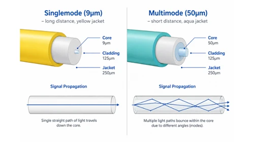
In 4G LTE, the FTTA fronthaul link ran CPRI (Common Public Radio Interface) - a dedicated TDM-over-fiber connection between the Baseband Unit (BBU) and the Remote Radio Head (RRH). For a typical 20 MHz LTE carrier with two antenna ports, the CPRI bitrate was around 1.2 Gbps. A single OS2 singlemode fiber pair handled it comfortably, and the distance limit was set by the optical transceiver class, not by anything latency-critical.
5G NR changes three things that directly affect the passive fiber specification:
Higher fronthaul bandwidth: A 100 MHz NR carrier with 64×64 Massive MIMO requires between 9.8 Gbps (downlink) and 15.2 Gbps (uplink) under CPRI Option 8 - a rate that is impractical for point-to-point fiber with current optical modules at reasonable cost. The eCPRI v2.0 specification (May 2019), published by Ericsson, Huawei, Nokia, and NEC, reframes this with flexible intra-PHY functional splits that can reduce fronthaul bandwidth by up to 10× compared with CPRI. Most deployed 5G networks use eCPRI Split 7.2x, which keeps Massive MIMO beamforming at the Radio Unit, and requires 10–25 Gbps of fronthaul capacity per sector.
Three-level node hierarchy: 5G NR disaggregates the baseband into CU (Central Unit), DU (Distributed Unit), and RU (Radio Unit / AAU). The critical passive fiber link runs between DU and RU - this is the FTTA fronthaul path that this article addresses. The CU-to-DU midhaul and the core-to-CU backhaul are separate network segments.
Tighter latency budget: The O-RAN Alliance specifies a one-way fronthaul latency of ≤100 µs for Split 7.2x, which limits the DU-to-RU fiber distance to approximately 10 km over standard G.652.D singlemode fiber (Ericsson packet fronthaul white paper, 2023). This is usually not the limiting factor for conventional macro-tower FTTA, where the run is often tens to a few hundred metres, but it matters for C-RAN designs connecting a centralized DU to multiple distant radio sites. Always verify reach against the actual O-RAN split, timing design and optics specification.

For passive fiber component selection, these changes matter in one concrete way: more fibre pairs per site and higher sensitivity to connector loss. A 4G site might have run a 4F feeder cable for two RRHs. A 5G macro site with three sectors, one AAU per sector, and the standard 2F-per-AAU minimum requires at least 6F - and industry practice is to specify a 12–24F armoured feeder to include operational spares and future AAU additions. Connection loss that was negligible on a 1.2 Gbps CPRI link becomes a real margin issue on a 25 Gbps eCPRI transceiver.
Outdoor Requirements for FTTA Components
A 5G tower site is not "outdoors" in the same sense as a buried cable or an equipment shelter. The environment at 50 metres above grade on a steel lattice structure is one of the harshest in civil infrastructure: direct solar radiation without shade, full wind exposure, rain that enters horizontal at 80 km/h, coastal salt spray in many markets, and temperature swings that can exceed 50°C between night and day. Every component that runs above the tower base cabinet must be specified for this environment, not for the equipment room at the bottom.
UV Radiation
LSZH (Low Smoke Zero Halogen) cable jackets - the correct choice for indoor use - are not UV-stabilised for prolonged direct sun exposure. Non-UV-stabilised LSZH compounds can become brittle under prolonged tower-top UV exposure, sometimes within only a few years in high-sun, high-temperature environments. The correct specification for any cable or assembly directly exposed to sunlight on a tower is a black HDPE or PE jacket tested to ISO 4892-2 (xenon-arc artificial weathering, minimum 1000 hours at 0.51 W/m²·nm at 340 nm). Silicone and PU/TPU jackets are also UV-stable and are used for flexible jumper assemblies at the tower-top RRU interface.
Temperature Cycling
Daily temperature swings of 30–50°C are common at tower-top in subtropical and high-altitude environments. Seasonal operating range for telecom-grade components must cover –40°C to +70°C, with some tropical ground-level installations reaching +85°C inside enclosures. Fiber cable assemblies must maintain insertion loss variation of ≤±0.3 dB across the operating temperature range as tested per IEC 60794-1-21 method F1. Connectors that use polyurethane boot materials (not silicone) may crack below –30°C if installed in high-latitude markets.
Waterproofing: IP68 per IEC 60529
IP68 per IEC 60529 requires the device to be protected against continuous submersion under specified conditions - typically 1 metre depth for a minimum of 30 minutes. For tower-site FTTA junction boxes and inline splice closures, IP68 is the preferred baseline for components directly exposed to weather or repeated water contact. IP67 may be insufficient for sites exposed to ponding water at the tower base or monsoon flash flooding, so the final rating should follow the site survey and operator standard. Connectors mounted at the RRU interface must also carry individual IP68 ratings, not just the enclosure - an IP68 box with a standard LC pigtail hanging out of a cable gland defeats the purpose entirely.
Mechanical Load
A 100-metre cable run from BBU room to tower-top endures both installation pull forces and long-term static gravity load. Minimum specifications for tower-grade feeder cable:
- Short-term maximum tensile load (installation): typically 1.0–2.7 kN, depending on cable OD and strength-member design.
- Long-term static load: typically 250–600 N for cables in vertical runs secured by clamps.
- Minimum clamp spacing: every 300–400 mm on vertical tower leg or cable tray, using UV-resistant stainless steel P-clips (not zip ties alone).
- Crush resistance: Where cables share trays with power cables, corrugated steel tape or interlocked steel wire armour provides protection against cable crush and rodent damage.
Wind-Induced Vibration
Wind-induced resonance on tall towers creates cyclic bending stress at every cable clamp. G.657.A2 fiber with a 10mm minimum static bend radius is more resilient to this than G.652.D (15mm static bend radius), particularly at tower-top where cables must route around mounting brackets. Using the wrong fiber type - standard G.652.D in a tight-bend routing through an AAU bracket - can cause localized macrobend losses that worsen progressively over years of wind vibration.
FTTA Product Stack at a 5G Macro Site
A complete FTTA link from BBU to AAU crosses four distinct environmental zones, each with different product requirements. The table below maps each zone to the appropriate product and the key specification that determines suitability.

Zone 1 - BBU Room: LC Patch Cord and Fiber Adapter
The BBU room environment is the easiest on the FTTA link: controlled temperature, low humidity, protected from mechanical damage. Standard OS2 LC fiber patch cord assemblies suffice here - LSZH jacket, 2 mm or 3 mm diameter, LC/UPC or LC/APC depending on the BBU interface. The
fiber optic adapter panel at the ODF is the demarcation point between the indoor patch cord and the feeder cable system. Use ceramic ZrO₂ ferrule LC/LC adapters for minimum mating loss variation over the life of the site.
Zone 3 - Tower Climbing Feeder Cable: Specification in Detail
This is the component that determines the long-term reliability of the FTTA link and is most commonly under-specified. Key decisions:
- Fiber type: G.657.A2 for any route with bend radii below 15 mm (common in cable tray corners and AAU bracket exits). G.652.D for straight runs with minimum 15 mm bend radius.
- Fiber count: 12F minimum for a 3-sector site (2F per AAU + 6F spare). 24F for sites with dual-band AAUs or anticipated future densification.
- Jacket: Black HDPE for all directly exposed runs. Black LSZH only where cables pass through fire-rated building sections at the base (transition sleeve required).
- Armour: Steel wire armour for crush resistance in shared cable trays. All-dielectric construction available for sites in lightning-prone areas where metal paths increase strike risk.
- Water blocking: Water-blocking yarn or gel filling in the core to prevent longitudinal water migration after jacket damage.
Why Pre-Terminated FTTA Cable Assemblies Are Usually the Safer Choice at Height
The economics and safety requirements of tower work make field splicing difficult to control at scale. Exact climb cost varies by country, access rule, rigging method and contractor, but every repeat climb adds delay and risk. Field splicing at 50+ metres in wind may require:
- A fusion splicer rated for outdoor use (most are not vibration-tolerant at height)
- Clean, low-humidity conditions (wind and dust compromise arc alignment)
- A certified splicer with access at height - a separate specialist from the rigger
- A second climb if the OTDR test fails after the first splice attempt
CommScope's published data for their HELIAX FTTA programme - validated across multiple operator 5G rollouts - showed that pre-terminated plug-and-play FTTA solutions reduced total site installation time by more than 50% versus field-spliced approaches, covering fiber configuration, power cable work, and mounting (CommScope press release, BusinessWire, 2021).
What Factory Termination Guarantees That Field Termination Cannot
Every pre-terminated assembly from Glory Optical ships with a per-pair insertion loss and return loss test certificate:
- Insertion Loss: ≤0.3 dB per connector (typical ≤0.15 dB)
- Return Loss: ≥55 dB (APC connectors) / ≥50 dB (UPC connectors)
- End-face geometry verified per IEC 61300-3-35 under 400× inspection
- Outdoor boot / waterproof seal integrity verified before shipment
Field-polished connectors depend on technician skill, equipment calibration, wind, dust and humidity - variables that are difficult to control at height. A factory-polished LC/APC connector achieves RL ≥55 dB consistently; a field-polished connector at tower-top on a humid or dusty morning may deliver materially lower return loss , increasing the risk of marginal performance on high-bandwidth fronthaul optics.
Glory Optical offers a full range of pre-terminated outdoor fiber patch cord for FTTA and custom assembly configurations including
FullAXS LC fiber patch cable for Ericsson interfaces and
ODC FullAXS LC outdoor patch cord configurations.
FTTA Component Selection Parameters for 5G Sites
The table below is a field engineer's specification checklist. The two-column structure separates requirements for the feeder cable run (Zone 3, BBU to tower base) from the tower-top jumper (Zone 4, junction box to RRU/AAU port).
Connector Type Selection: Vendor Compatibility
The single most common procurement error on FTTA projects is ordering the wrong connector type for the installed RRU vendor. The connector must match the RRU/AAU interface port - not just mechanically, but in boot geometry and sealing. A summary of the dominant types:

FTTA Site Maintenance: Three Practices That Prevent Most Avoidable Failures
Based on anonymized field feedback from 5G macro deployments in Southeast Asia and the Middle East, many avoidable FTTA service issues trace back to three maintenance failures: dirty connectors, missing drip loops, and missing strain relief. None of these requires expensive equipment to prevent - they require a maintenance protocol, enforced at site acceptance.
1. End-Face Cleaning to IEC 61300-3-35
Contamination of the connector end-face is the leading cause of FTTA link degradation on in-service sites. Wind-blown dust, condensation, and insect debris accumulate on unmated connector faces - particularly at tower-top connectors that are temporarily disconnected during RRU maintenance. The standard for acceptable cleanliness is IEC 61300-3-35, which defines Grade A (no contamination ≥3 µm in the core zone) as the requirement before any connection is made.
Required practice: use a one-click cassette cleaner immediately before every connection at tower-top, even for caps-protected connectors that have not been disconnected. For unmated connectors in outdoor enclosures, inspect with a 400× digital scope and use a dry wipe/IPA wipe sequence if contamination is visible. Refer to our fiber optic connector cleaning guide for a step-by-step protocol.
2. Drip Loops and Entry Sealing
Every overhead cable entry into a junction box or RRU port must include a minimum 300 mm drip loop below the entry point. Water follows the cable jacket surface under capillary action, and without a drip loop, it wicks directly into the connector body or closure gland. In coastal high-humidity environments, a poorly formed drip loop is the primary path for condensation into otherwise IP68-rated hardware.
At entry into junction boxes and closures, verify that the cable gland is torqued to specification and that the jacket is not kinked within 50 mm of the gland - kinks compromise the jacket seal and allow water ingress paths. After any closure re-entry for maintenance, re-test the IP rating per the manufacturer's re-sealing procedure.
3. Strain Relief and Cable Management
Cable assemblies are not designed to carry axial load through the connector ferrule. Every tower-top FTTA jumper must have a dedicated strain-relief bracket that takes the cable weight and any tensile load before it reaches the connector boot. Acceptable installation: stainless steel cable clamp on the cable jacket within 50 mm of the RRU port, with the clamp anchored to the mounting structure - not to the RRU itself. On the tower climbing section, P-clip spacing of every 300–400 mm prevents fatigue at clamp points during wind-induced vibration. Use UV-resistant stainless steel clips - standard galvanised zinc P-clips can corrode prematurely in coastal environments.
Label Management
Both ends of every fiber must be labelled with cable ID, fiber number, and origination/termination point. Standard adhesive polypropylene labels fade and fall off within 12 months at tower-top UV exposure. Use UV-resistant polyester (e.g., Brady B-581 or equivalent) or anodised aluminium wrap tags. Color-code by sector: blue / orange / green is the common convention for 3-sector sites. Incorrect fibre identification is the leading cause of unnecessary tower climbs for faults that don't exist.
Field Notes: Recurring Failure Patterns on 5G Tower Sites
The examples in this section are written as anonymized field notes for practical design review. They should be treated as deployment lessons, not as universal failure-rate statistics.
The following failure patterns are drawn from discussions with tower contractors and RF engineers across 5G macro rollouts in Indonesia, the Gulf region, and West Africa (2023–2025). They represent recurring, preventable failures - not random equipment defects.
Failure Mode 1: Connector Contamination at First Commissioning
In an anonymized multi-site 5G macro rollout in Indonesia, a significant share of tower-top LC connection issues at commissioning were traced to contamination introduced during handling. The connectors had protective dust caps fitted, but caps were removed and connectors handled without cleaning before mating. Resolution: a mandatory one-click cleaning + 400× inspection protocol was added to the site acceptance checklist, applied to every connector immediately before mating, regardless of whether it had been disconnected. Subsequent sites showed far fewer connector-related retests after the protocol was enforced.
Failure Mode 2: Wrong Cable Length - Too Short, Not Too Long
In an anonymized Gulf-region 5G upgrade, several feeder cable runs required early replacement because the cables were ordered too short. The BOM had been generated from 2D tower drawings that did not account for cable routing around equipment platforms and cable tray dog-legs. Root cause: the site survey measured straight-line vertical distance, not the actual cable route. Resolution: a 15% slack factor was added to all cable length calculations, and a coiled service loop (minimum 1.5 m) was mandated at both the tower base junction box and the tower-top closure for each run. Slack storage prevents cable tension at connectors during RRU replacement.
Failure Mode 3: UV-Degraded LSZH Jacket on Tower Run
At a coastal installation in West Africa, LSZH-jacketed cables used in directly exposed outdoor tower runs showed visible jacket cracking and embrittlement during later inspection, well before the expected cable life. Several runs required replacement. Root cause: a procurement substitution had replaced black HDPE outdoor cable with LSZH-jacketed cable of the same outer dimensions, sourced from a different supplier during a stock shortage. The substitution passed the initial IP and bend radius checks because the outer geometry was identical. Correct specification: black HDPE jacket should be specified for directly exposed outdoor tower cable runs unless a project-approved UV-stable alternative is documented; LSZH must be explicitly excluded from these zones in the specification document, not just assumed to be excluded. More on outdoor cable selection in our direct burial outdoor fiber cable guide and our
fiber optic bend radius guide.

Request a Custom FTTA BOM from Glory Optical
Glory Optical has supplied FTTA passive fiber components to 5G fronthaul rollouts in the Middle East, Southeast Asia, and Africa. Our engineering team works directly from tower layout drawings and RRU vendor datasheets to generate item-level BOMs that account for cable routing, slack allowances, vendor-specific connector compatibility, and environmental requirements.
Our custom FTTA cable assembly service covers pre-terminated jumper assemblies from 0.3 m to 200 m, all major RRU connector types (DLC, NSN Boot, FullAXS, ODVA), and OEM labelling / custom packaging for volume rollout programmes. All assemblies ship with per-pair IL/RL test certificates and are manufactured to ISO 9001:2015 under full batch traceability.
FAQ
Q: What fiber type should I use for 5G FTTA tower-top jumpers?
A: For tower-top jumpers and routes around RRU/AAU brackets, G.657.A2 bend-insensitive single-mode fiber is usually preferred because it tolerates tighter bends than standard G.652D. For longer, straight feeder runs with controlled routing, G.652D is still commonly used and can be more economical. Confirm the final selection against the actual routing radius and operator specification.
Q: Which connector type do I need for Huawei, Ericsson and Nokia RRU/AAU interfaces?
A: Connector choice is model-specific. Common examples include DLC-style weatherproof dual-LC interfaces, NSN Boot LC duplex, FullAXS / ODC-style outdoor LC interfaces and ODVA multi-fiber interfaces. Treat any vendor table as a starting point only; always verify the connector geometry, keying and seal design against the radio datasheet or port drawing before ordering pre-terminated assemblies.
Q: How many fibers does a 3-sector 5G macro site require?
A: A simple 3-sector site with one AAU per sector normally needs at least 6 fibers for duplex fronthaul. In procurement, many projects specify 12F or 24F feeder cable to allow spare fibers, future radio additions and easier maintenance. The right count depends on sector count, radio count, redundancy plan and operator expansion policy.
Q: What IP rating is required for FTTA outdoor fiber closures and connectors?
A: For components directly exposed to outdoor weather, IP68 is a common planning baseline, especially where rain, flooding, condensation or repeated washing may occur. Sheltered locations may allow lower ratings under some operator rules, but exposed tower-top connectors and tower-base closures should be selected by site survey rather than by indoor cabinet assumptions.
Q: What is the maximum fronthaul fiber distance for 5G RRU/AAU?
A: The practical distance depends on the functional split, timing budget, optics, equipment vendor and operator design. Conventional tower FTTA runs are often only tens to a few hundred metres. Centralized DU-to-RU designs can be much longer, but O-RAN Split 7.2x and synchronization requirements must be checked carefully against the actual network design.
Q: Why choose pre-terminated FTTA assemblies over field splicing?
A: Pre-terminated assemblies move polishing, inspection and IL/RL testing into the factory, where conditions are controlled and every pair can be documented before shipment. This is especially useful at tower-top, where wind, dust, humidity and access limitations make field termination less repeatable. Field splicing still has a role in some feeder and repair work, but tower-top jumpers are usually better treated as tested plug-and-play assemblies.
Recommended FTTA Components by Site Zone
The article above explains the engineering sequence. The product selection below is grouped by site zone so procurement teams can turn the design into an RFQ without turning the guide into a product catalogue.
LC Patch Cord + Adapter Panel
Use OS2 LC/UPC or LC/APC patching between the equipment port and ODF. Confirm polarity, ferrule type and test report format.
View patch cordsIP-Rated Closure / Junction Box
Use sealed closures or junction boxes for feeder entry, splicing and adapter management. Confirm IP rating, cable gland range and splice capacity.
View closuresOutdoor Feeder Cable
Select UV-stable, water-blocked and mechanically protected cable according to tower route, clamp spacing and lightning/metal-path constraints.
View outdoor cablePre-Terminated FTTA Jumper
Choose DLC, NSN Boot, FullAXS, ODVA or outdoor LC based on the radio model. Request per-pair IL/RL test reports before shipment.
View cable assembliesStandards & References
The following references help engineers verify the values used in 5G FTTA design, component selection and acceptance testing. Always check the current edition and the radio vendor's port specification before final procurement.
| Reference | Why it matters in an FTTA solution |
|---|---|
| eCPRI Specification v2.0 | Defines the Ethernet-based fronthaul direction used by many 5G radio deployments. |
| ITU-T G.652 | Standard single-mode fiber used in controlled feeder routes. |
| ITU-T G.657 | Bend-insensitive single-mode fiber categories for tight access and jumper routing. |
| IEC 60529 / IP ratings | Ingress protection classification for outdoor closures, connector boots and enclosures. |
| IEC 61300-3-35 | Connector end-face inspection and pass/fail criteria for contamination control. |
| IEC 60794 series | Optical fiber cable testing methods relevant to temperature, tensile and mechanical performance. |
About Glory Optical: Ningbo Glory Optical Communication Co., Ltd. supplies FTTH / FTTx and 5G FTTA passive optical components including outdoor fiber cable, IP-rated closures, cable assemblies, pigtails, patch cords, adapters and OEM/ODM customized products. Product values in this article should be confirmed against the latest datasheet or project-specific RFQ.
Document note: This guide is for technical planning and procurement support. It does not replace local codes, operator standards, certified design review, radio vendor port drawings or product-specific installation instructions.