The 60-Second Design Answer
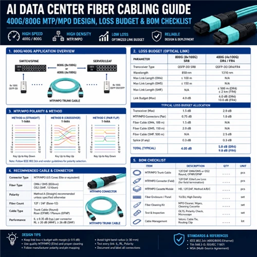
For a new AI data center, product names such as "fiber box" or "MPO cable" are not enough to define a reliable fiber plant. Start with a 400G/800G design checklist and BOM path: confirm the transceiver PMD, map each port to the required fiber count, select the MTP/MPO base that matches the optical lanes, route trunks through documented patch panels, reserve OS2 backbone capacity where the upgrade path is uncertain, calculate the loss budget, and define acceptance testing before the purchase order is released.
| Design decision | Recommended starting point | Why it matters in AI clusters |
|---|---|---|
| Backbone fiber | OS2 singlemode for new backbone or upgrade-uncertain routes; G.657.A1/A2 options where tight routing is expected | Preserves reach and upgrade flexibility from 400G to 800G and possible future 1.6T routes; OM4/OM5 can still fit fixed short SR links. |
| Parallel optics | 400GBASE-DR4, 800GBASE-DR8 or vendor-defined 2×400G breakouts | GPU fabrics are dense and repetitive; one wrong MPO base can strand fibers or break lane mapping across hundreds of links. |
| MTP/MPO trunk | Base-8 for DR4 as a starting point; MPO-16 or dual MPO-12 for DR8 / 2×DR4 after checking the exact module interface | The trunk base should follow the optical lane count; legacy Base-12 inventory needs a migration map before reuse. |
| Patch panel / fiber box | High-density MPO patch panel, cassette or adapter panel with documented polarity | Panels are not only storage hardware; they define density, bend radius, polarity management and future change control. |
| Loss budget | Per-link worksheet: fiber loss + mated pairs + cassette/adapters + splices + margin | 400G/800G margins are tighter; every connector pair and contaminated end face becomes visible. |
| Acceptance testing | Tier 1 OLTS, polarity, length and end-face inspection; Tier 2 OTDR where required | Factory-tested assemblies reduce risk, but final installed plant must still be certified before handover. |
The 400G/800G Design Checklist Before You Request a Quote
| Checklist item | What to specify | Supplier / QC evidence to request |
|---|---|---|
| Switch and NIC port speed | 400G, 800G or 800G split into 2×400G / 4×200G | Transceiver part number and front-panel connector interface |
| Optical PMD | SR, DR, FR, LR, DR4, DR8, 2DR4 or vendor-specific breakout | Datasheet reach, insertion-loss limit and connector requirement |
| Fiber type | OS2 G.652.D for long-life backbone routes; OM4/OM5 where SR reach, port density and refresh path are fixed | Cable datasheet, attenuation value and jacket/fire rating |
| MTP/MPO base | Base-8, Base-16, dual MPO-12 or breakout assembly | Lane map drawing and polarity diagram attached to the BOM |
| Connector polish and gender | APC for many singlemode MPO parallel-optics modules; confirm polish and gender per datasheet | IL/RL test report and end-face inspection report |
| Patch panel / cassette | 1U/2U density, cassette count, front adapter type, rear MPO type, cable manager | Port map, cassette polarity and label template |
| Loss budget | Maximum channel loss, planned loss, reserved margin and reflectance requirement | Per-link worksheet plus factory IL/RL report |
| Acceptance test | Tier 1 OLTS, polarity, length, connector inspection; OTDR where required | As-built report package, trace files and pass/fail table |

400G/800G cabling design workflow: switch port → transceiver PMD → MTP/MPO base and fiber count → patch panel and cassette polarity → OS2 backbone → loss budget worksheet → supplier-ready BOM.
AI Fabric Architecture: Why Cabling Must Follow the GPU Topology
AI data center cabling is not ordinary server-to-core cabling. Large GPU clusters move east-west traffic constantly for training, inference batching and storage access. The fiber plant must therefore support leaf-spine or rail-optimized fabric designs without creating polarity ambiguity, congestion in patching zones or undocumented spare fibers.
NVIDIA publicly describes Spectrum-X as an Ethernet platform designed for AI networking, including multi-plane designs that scale AI workloads beyond single-plane limits. For cabling teams, the lesson is practical: each rail, plane or leaf-spine path must have a physical label, a documented fiber map and a testable link budget. NVIDIA Spectrum-X platform reference.
This guide focuses on the Ethernet/RoCE physical layer, which is the most common fiber-cabling path for new AI fabrics. InfiniBand NDR/HDR fabrics use different transceiver and cable conventions and are outside this guide's scope; treat InfiniBand cabling as a separate design exercise rather than assuming the same MTP/MPO base and polarity rules apply. For very short links - typically server-to-ToR runs of roughly 1–3 m - active optical cables (AOC) and passive copper DAC are common alternatives to a fiber trunk and transceiver pair, trading cabling flexibility for lower cost at fixed, short distances. As reach or rail count grows, the fiber-based design in this guide becomes the more flexible choice.

Leaf-spine AI fabric architecture: GPU racks connect to ToR leaf switches via Base-8 or Base-16 MTP/MPO trunks; high-density patch panels manage polarity and label continuity at each hop; OS2 backbone links spine and aggregation layers with per-rail topology labeling throughout.
In AI fabrics, the cleanest physical-layer rule is: the cable label must match the network topology. If a topology uses rail 1, rail 2, rail 3 and rail 4, the patch-panel label, trunk label and test report should carry the same rail identifier. This prevents a working optical link from being placed in the wrong logical path.
Label different AI data center link groups separately
| Link group | Typical traffic role | Cabling implication |
|---|---|---|
| Backend GPU fabric | GPU all-reduce, east-west training traffic and rail-optimized paths | Use the strictest lane map, rail label, polarity record and loss-budget control. |
| Frontend / service network | Management, API, user access and orchestration traffic | May use different port speeds or duplex links; keep labels separate from GPU fabric rails. |
| Storage fabric | Dataset movement, checkpointing and distributed storage access | Document high-bandwidth uplinks and avoid mixing storage patching with GPU rail trunks. |
| Backbone / DCI route | Spine aggregation, inter-room, campus or inter-building traffic | Prefer OS2 with spare panel density and separate Tier 1 / Tier 2 acceptance records where required. |
Transceiver-to-Fiber Mapping: Start Here Before Choosing Any Cable
Every BOM error starts as a mapping error. The transceiver defines the lane count, connector interface, reach, polish and maximum channel insertion loss. The MTP/MPO trunk and patch panel must follow that interface.
| Application | Typical reach | Fiber / connector direction | BOM implication |
|---|---|---|---|
| 400GBASE-DR4 | Up to 500 m over OS2 | 8 fibers on MPO-12 mechanical interface, singlemode parallel lanes | Use Base-8 MTP/MPO trunk, APC polish where specified, Type-B polarity and documented pinning. |
| 800GBASE-DR8 | At least 500 m over 16 singlemode fibers | MPO-16 APC or dual MPO-12 APC depending on module vendor | Confirm whether the transceiver requires MPO-16 or dual MPO-12 before ordering trunks and panels. |
| 800G → 2×400G breakout | Usually up to 500 m for DR-based breakouts | One 800G port mapped to two 400G optical paths | Specify breakout assembly type, lane map, polarity, labels and destination ports in the BOM. |
| 400G/800G FR or LR | 2 km to 10 km class, depending on PMD | Duplex OS2 with LC or vendor-defined interface | Useful for longer room, campus or DCI links; density shifts from MPO trunk to duplex patching. |
| SR multimode links | Short-reach inside a row or room | OM4/OM5, MTP/MPO parallel optics | Valid when distance is stable; less flexible for long-term 800G/1.6T singlemode migration. |
The TIA Fiber Optics Tech Consortium 400GBASE-DR4 overview lists a 3.0 dB maximum insertion loss and 500 m OS2 operating range for 400GBASE-DR4. Its 800GBASE-DR8 overview describes 800 Gb/s PAM4 parallel transmission over 16 singlemode fibers with reach up to at least 500 m. Cisco's public 800G OSFP data sheet also shows why vendor-interface confirmation matters: one DR8 model uses dual MPO-12 APC and another DR8P model uses MPO-16 APC, both supporting 800GBASE-DR8 and 2×400GBASE-DR4 breakouts. Cisco 800G OSFP transceiver reference.
MTP/MPO Trunk Design: Base, Polarity, Gender and Polish
MTP/MPO is not one cable type. For 400G/800G, the purchasing team must specify at least four variables: base/fiber count, polarity, gender and polish. A quote that says only "MPO trunk, OS2, 30 m" is incomplete.

Base selection determines whether all fibers carry optical lanes. Base-8 is a clean fit for 400GBASE-DR4 (four Tx + four Rx lanes). MPO-16 or dual MPO-12 usually matches 800GBASE-DR8 (eight Tx + eight Rx), depending on the module. Base-12 applied blindly to a DR4 design can strand four fibers per trunk and add polarity complexity without clear benefit.
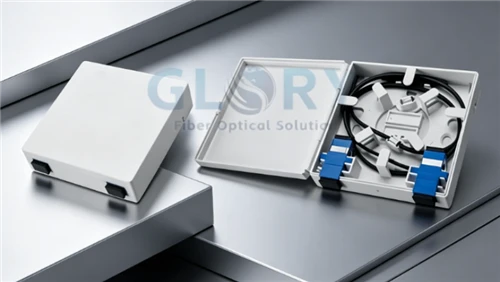
Patch Panels, Cassettes and ODFs: The Patching Layer in AI Data Center Cabling
In an AI data center, the patching layer - rackmount fiber patch panel, MPO cassette enclosure or ODF - is where MTP/MPO trunks terminate, LC breakouts are managed, bend radius is controlled and future changes are made without disturbing the backbone. For 400G and 800G AI fabric designs, panel selection directly affects lane integrity, polarity management and operational change control at every moves-adds-changes event.
Prioritize fiber optic patch panels, MTP/MPO cabling systems and data center cabling solutions designed for parallel-optics density and documented polarity. For enclosure categories outside the AI data center context, see the Fiber Box buyer's guide.
| Panel decision | Good specification | Risk if missing |
|---|---|---|
| Rack density | 1U or 2U panel, cassette count, port count and reserve ratio | Future 800G expansion forces unplanned panels and longer patch cords. |
| Front interface | MPO adapter, LC duplex, LC breakout or mixed interface | Incorrect patching method for the selected optics. |
| Rear interface | MTP/MPO trunk entry, cable gland, bend-radius manager and strain relief | High-density trunks are mechanically stressed during moves/adds/changes. |
| Cassette polarity | Documented Type-A/B/C or custom mapping with test report | Link light fails or TX/RX lanes land in the wrong place. |
| Labeling | Rack, panel, port, rail/plane, trunk ID, far-end port and test ID | A valid cable becomes operationally unusable because no one trusts the map. |
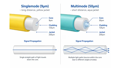
OS2 vs OM4 in AI Data Centers: Why Singlemode Should Be the Default for New Builds
OM4 and OM5 remain correct for short SR applications, particularly inside a row where link distance is stable and the upgrade path to singlemode is not planned in the near term. For new structured backbone routes - spine-to-leaf, inter-row, inter-room, or any route where the future speed roadmap is uncertain - OS2 singlemode is, as a Glory Optical engineering recommendation, the safer planning default. It provides more reach, supports DR/FR/LR optical families and reduces the chance that a bandwidth upgrade becomes a backbone recabling project.
| Fiber choice | Where it fits | Where to be careful |
|---|---|---|
| OS2 G.652.D | Main structured backbone, spine/leaf aggregation, room-scale and campus-scale paths | Requires singlemode transceivers and APC/reflectance discipline for MPO parallel links. |
| G.657.A1/A2 bend-tolerant OS2 | Tight cable managers, high-density trays, equipment-side routing | Confirm compatibility with project standard and connector assembly process. |
| OM4 / OM5 | Short SR links where link distance and refresh path are fixed | Distance and migration limits make it less flexible as a universal backbone for AI clusters. |

Fiber selection decision path: stable intra-row SR links may use OM4/OM5 where distance and upgrade path are fixed; room-scale and building-scale DR or FR links default to OS2; any backbone route that may carry 800G or future 1.6T traffic should be OS2 with reserved panel density from day one.
400G/800G Loss Budget Worksheet: Turn the Cabling Design Into a Pass/Fail Number
The loss budget is where architecture becomes measurable. A useful BOM should not only list trunks and panels; it should state the expected insertion loss and reserved margin for every link type.
Planning formula
Total planned loss = fiber attenuation + mated connector pairs + cassette/adapter interfaces + splice loss + test allowance.
Then compare the result against the application maximum channel insertion loss from IEEE/TIA guidance or the exact transceiver datasheet. Reserve extra margin for contamination, future patching and field handling.
| Loss element | Example planning value | How to use it |
|---|---|---|
| OS2 fiber attenuation | Use project wavelength/datasheet; 1310 nm planning often uses ≤0.4 dB/km per ITU-T G.652.D | Length in km × attenuation value. |
| Mated MPO/LC pair | 0.20–0.35 dB per pair depending on grade and project spec, consistent with TIA-568.3-E component performance guidance and IEC 61300-3-34 random-mated attenuation grading | Count every transceiver, panel, cassette and patching interface. |
| Fusion splice | 0.05–0.10 dB planning value, measured per the IEC 61300-3-4 attenuation measurement procedure | Use only where splicing is present; many pre-terminated data center links avoid field splices. |
| Return loss / reflectance | Follow connector polish and PMD requirement | Especially important for singlemode MPO parallel optics. |
| Operational margin | Project-specific reserve | Protects against cleaning variation, re-patching and measurement uncertainty. |
Example: 400GBASE-DR4, OS2, 120 m, two panel hops
| Item | Count / length | Planning value | Loss |
|---|---|---|---|
| OS2 cable | 0.12 km | 0.4 dB/km | 0.048 dB |
| Mated MPO pairs | 4 | 0.25 dB | 1.00 dB |
| Splice events | 0 | 0.05 dB | 0.00 dB |
| Planned channel loss | Fiber + connector pairs + splices | 1.05 dB | |
| 400GBASE-DR4 reference limit | TIA FOTC application overview | 3.0 dB max | |
| Planning margin | Before contamination and project-specific penalties | ~1.95 dB | |

Loss budget breakdown for a 400GBASE-DR4 example link at 120 m OS2 with two panel hops: ~0.048 dB fiber attenuation + 1.00 dB for four mated MPO pairs (0.25 dB each) = 1.05 dB planned channel loss, leaving ~1.95 dB margin before the 3.0 dB application limit. Every additional connector pair, cassette interface or contaminated ferrule reduces this margin.
Acceptance Testing: Prove the Plant Before the AI Cluster Goes Live
Factory test reports are valuable, but they do not replace installed-link acceptance. TIA-568.3-E covers optical fiber cabling and components, including performance, transmission, test and measurement requirements and polarity transition methods. TIA-568.3-E overview.
| Test layer | What it checks | Recommended deliverable |
|---|---|---|
| End-face inspection | Debris, scratches and defects before mating | IEC 61300-3-35 pass/fail record for critical MPO and LC interfaces |
| Tier 1 OLTS / LSPM | Insertion loss, length and polarity against the application loss limit | Per-link pass/fail report tied to panel and port labels |
| Tier 2 OTDR | Connector/splice events, reflectance, macro-bend, abnormal attenuation | Trace file and event table for long routes or troubleshooting |
| Label verification | Near-end/far-end ID, rail/plane, rack and port consistency | As-built link map and QR/CSV export for operations |
Connector cleanliness deserves a separate line in the acceptance plan. IEC 61300-3-35:2022 is concerned with the observation and classification of debris, scratches and defects on fiber optic connector end faces. IEC 61300-3-35 reference. For practical cleaning procedure details, link readers to the Glory Optical fiber optic connector cleaning guide.

Three-stage acceptance testing workflow: (1) inspect every MPO and LC connector end face against IEC 61300-3-35 pass/fail criteria before mating; (2) OLTS Tier 1 insertion-loss, length and polarity test against the project loss-budget target; (3) OTDR Tier 2 trace and event-table documentation for long backbone routes and complete as-built records.
Pre-terminated MTP/MPO assemblies should ship with a factory report that can be traced to the project BOM and production lot. Request both a PDF summary and raw data file at order placement. Factory test results do not replace installed-link Tier 1 acceptance; both are required before handover.
| Factory report field | What the buyer should verify | Why it matters |
|---|---|---|
| Insertion loss | Per fiber, all channels, both directions where specified | Confirms the assembly supports the planned channel-loss target before installation. |
| Return loss | Measured against the connector polish and PMD requirement | Controls reflectance risk in singlemode PAM4 parallel optics. |
| Polarity and pin map | Lane map, key orientation, male/female interface and far-end mapping | Prevents TX/RX mismatch across trunk, cassette and equipment ports. |
| End-face inspection | Pass/fail record against IEC 61300-3-35 criteria | Reduces contamination risk before first mating. |
| 3D geometry / lot traceability | Radius of curvature, vertex offset and fiber height where required, plus lot number | Supports batch-level QC and post-delivery troubleshooting. |
400G/800G BOM Checklist: Copy This Into the RFQ
A good supplier can only quote accurately when the BOM carries engineering intent. Use the table below as the core RFQ checklist for Glory Optical or any other qualified manufacturer.
| BOM field | Required detail | Example entry |
|---|---|---|
| Project topology | Leaf-spine, rail-optimized, front-end/back-end split, rack count | GPU Rack 01–16, two-tier leaf-spine, 4 rails |
| Switch / NIC model | Vendor, model, port speed and port count | 800G OSFP switch to 400G QSFP-DD NIC breakout |
| Transceiver PMD | DR4, DR8, 2DR4, FR4, LR4, SR8 and reach | 800GBASE-DR8, 500 m |
| Fiber type | OS2 / OM4 / OM5, fiber count and jacket | OS2 G.652.D, LSZH, 96F trunk route |
| MTP/MPO trunk | Base, fiber count, length, gender, polish, polarity | MPO-16 APC female, Type-B, 30 m, low-loss |
| Patch panel | 1U/2U, cassette/adaptor count, front/rear interface | 1U 4-cassette MPO panel with front MPO adapter ports |
| Breakout assembly | Required only for split ports; include lane map | MPO-16 APC to dual MPO-12 APC, 800G to 2×400G |
| Labels | Rack, panel, port, rail, far-end port, trunk ID | R07-P1-MPO03 → Spine02-P17, Rail 2 |
| Test documents | IL/RL, polarity, end-face inspection, OTDR if required | PDF + CSV per trunk and per installed link |
| Compliance | ISO 9001, RoHS, CE where applicable, material and fire rating | See certificate package and batch report |
A structured BOM response for a 400G/800G project should include the engineering fields below for each item, not only a product name and length.
| BOM line field | Example value |
|---|---|
| Connector and base | MPO-16 APC female, Type-B, low-loss grade |
| Fiber and jacket | OS2 G.652.D, LSZH, 30 m |
| Performance target | IL ≤0.35 dB per mated pair, RL target per module datasheet |
| QC package | Factory IL/RL report, polarity map, IEC 61300-3-35 end-face pass record, PDF + CSV |
| Traceability | Project BOM number, lot number and label template |
Example RFQ scenario for a small AI fabric
| Input from project team | How it changes the fiber BOM |
|---|---|
| 16 GPU racks, 4 backend rails, two-tier leaf-spine fabric | Labels must carry rack, panel, port and rail ID; rail trunks should not be mixed with frontend or storage links. |
| 800G OSFP ports breaking out to 2×400G DR4 links | Supplier must confirm MPO-16 vs dual MPO-12 interface and provide a breakout lane map before production. |
| 120 m average backbone route with two panel hops | Loss budget should count fiber attenuation, four mated pairs, cassette interfaces if present and reserved margin. |
| Future expansion expected within the same room | Patch panels should reserve density and route space; OS2 backbone trunks should include spare fibers where the owner requires migration capacity. |
Public Cases: Why Physical-Layer Discipline Matters at AI Scale
AI training jobs are sensitive to infrastructure interruptions because many workloads run synchronously across large GPU pools. Data Center Dynamics reported on Meta's Llama 3 training run using 16,384 NVIDIA H100 GPUs: over a 54-day period, Meta recorded 419 unexpected component failures, and network switch and cable problems accounted for 35 interruptions, or 8.4%. Data Center Dynamics summary of Meta report.
The lesson is not that every AI failure is caused by fiber. The lesson is that at 10,000+ GPU scale, even a small physical-layer error rate creates real operational pain. Documented polarity, factory-tested MTP/MPO assemblies, clean end faces, low-loss patching and traceable acceptance reports reduce one avoidable category of interruption.
Public vendor examples also show why interface details must be read before ordering. Cisco's 800G OSFP DR8 documentation lists both dual-MPO-12 APC and MPO-16 APC variants, and both support 800GBASE-DR8 plus 2×400GBASE-DR4 breakouts. That single example is enough to justify a stricter RFQ: never order "800G MPO trunk" without the exact module interface and breakout map.
Common 400G/800G Cabling Mistakes to Prevent
- Buying Base-12 because it is familiar. Base-12 may strand fibers in DR4 designs and can complicate 800G migration.
- Ignoring transceiver connector variants. 800G DR8 may appear as MPO-16 or dual MPO-12 depending on vendor and model.
- Treating polarity as an afterthought. Polarity must be designed across trunk, cassette, adapter and patch cord.
- Counting only cable length in the loss budget. Connector pairs and cassette interfaces often dominate short data center links.
- Using multimode as the default backbone without checking the refresh plan. OM4/OM5 can be correct for fixed SR links, but OS2 is usually safer for long-life backbone routes and uncertain AI fabric migration.
- Skipping end-face inspection. MPO connectors multiply the risk because one ferrule carries many lanes.
- Separating BOM and test plan. If the quote does not define test reports, acceptance becomes a negotiation after installation.
- Labeling only both ends, not the topology. AI fabrics need rack, panel, port, rail/plane and far-end identifiers.
Glory Optical BOM Outputs by Layer
The 400G/800G design checklist maps directly to product categories. Each layer of the AI fabric - parallel optics, patching and backbone - should be quoted as a BOM output with a defined test package, label format and migration assumption.
| Design input | BOM output | Glory Optical category |
|---|---|---|
| DR4 / DR8 / 2×DR4 optics and lane map | MTP/MPO trunk or breakout assembly with base, polarity, gender, polish and test report | MTP/MPO Trunk Cables |
| Rack count, panel density and moves/adds/changes plan | 1U/2U patch panel, cassette or adapter panel with port map and label template | Fiber Optic Patch Panels |
| Backbone distance, route uncertainty and upgrade plan | OS2 / OM4 / OM5 indoor backbone cable with spare capacity and jacket/fire rating | Indoor Backbone Fiber Cables |
MTP/MPO Trunk Cables
Base-8, Base-16, MPO-12, MPO-16, low-loss OS2 and OM4/OM5 assemblies for 400G/800G structured cabling.
View MTP/MPOFiber Optic Patch Panels
1U/2U high-density patch panels, MPO cassettes, adapter panels, cable managers and ODF options.
View Patch PanelsIndoor Backbone Fiber Cables
OS2, OM4 and OM5 indoor cable options for rack, room and building backbone routes.
View Indoor CablesCertificates & OEM Documentation
CE, RoHS, ISO 9001 and batch-level test documentation guidance for data center procurement teams.
Read Certification GuideFAQ
-
Q: What is the best fiber type for a new AI data center backbone?
A: As a Glory Optical engineering recommendation, OS2 singlemode is the default choice for new structured backbone designs where reach, future upgrade path or 800G/1.6T migration is uncertain. It supports DR, FR and LR optical families and reduces recabling risk. OM4 and OM5 remain useful for short SR links where distance and refresh plans are fixed.
Q: Should I use Base-8 or Base-16 MTP/MPO for 400G/800G?
A: Match the base to the optical lane count. 400GBASE-DR4 commonly maps to eight fibers on an MPO-12 mechanical interface. 800GBASE-DR8 uses sixteen fibers and may use MPO-16 or dual MPO-12 depending on the transceiver. Do not choose Base-12 simply because it is common in older inventory.
Q: Is Type-B polarity always correct for AI data center cabling?
A: Type-B is widely used for parallel optics because it reverses the fiber map end to end. However, it is only correct when the transceiver, cassette and trunk are designed together. Require a lane map and factory polarity report for every assembly.
Q: How many connector pairs can a 400GBASE-DR4 link include?
A: Start with the application maximum channel insertion loss and work backward. For 400GBASE-DR4, the TIA FOTC overview lists 3.0 dB maximum insertion loss. If each mated pair is planned at 0.25 dB, four pairs consume 1.0 dB before fiber loss and margin. The exact allowable number depends on the selected component grade, reflectance and transceiver requirement.
Q: What should be included in a 400G/800G cabling BOM?
A: A complete BOM should include the transceiver PMD and reach, fiber type, MTP/MPO base and fiber count, connector gender, polarity, polish, trunk length, breakout type, patch panel or cassette configuration, cable jacket/fire rating, labeling scheme, spare capacity, loss-budget target, and required test documents such as insertion loss, return loss, polarity, end-face inspection and OTDR reports where needed.
Q: How do you calculate a 400G/800G fiber loss budget?
A: Start with the application maximum channel insertion loss from the transceiver standard or datasheet. Add fiber attenuation based on length, then add each mated connector pair, cassette, adapter interface and splice. Compare the total against the allowed channel loss and reserve margin for contamination, handling and future patching. For parallel singlemode optics, also verify reflectance and connector polish, not just insertion loss.
Q: What test reports should a fiber cabling supplier provide?
A: For pre-terminated assemblies, request insertion loss, return loss, polarity, end-face inspection and 3D geometry where applicable. For installed links, require Tier 1 loss/length/polarity records and Tier 2 OTDR traces when the project owner requires event-level documentation.
Standards, Public Sources and Further Reading
- TIA FOTC: 400GBASE-DR4 Application Overview - 500 m OS2 reach and 3.0 dB maximum insertion-loss reference.
- TIA FOTC: 800GBASE-DR8 Application Overview - 800 Gb/s PAM4 over 16 singlemode fibers.
- TIA-568.3-E overview - optical fiber cabling and component performance, transmission, test and polarity requirements; also referenced for mated-pair insertion-loss planning values.
- ITU-T G.652.D recommendation - singlemode optical fibre and cable attenuation characteristics used for OS2 backbone planning values.
- IEC 61300-3-34 - basic test and measurement procedures for attenuation of random-mated connectors, referenced for mated MPO/LC pair loss grading.
- IEC 61300-3-4 - basic test and measurement procedures for attenuation, covering the planning value used for fusion splice loss.
- IEC 61300-3-35:2022 - visual inspection of fiber optic connector end faces.
- Cisco OSFP 800G Transceiver Modules Data Sheet - example of dual MPO-12 and MPO-16 800G DR8 interface variants.
- NVIDIA Spectrum-X Ethernet Platform - public AI Ethernet fabric reference.
- Data Center Dynamics: Meta Llama 3 training interruptions - public case showing network switch and cable issues at AI-cluster scale.
About Glory Optical: Ningbo Glory Optical Communication Co., Ltd. supplies data center cabling and passive optical components including MTP/MPO trunk cables, fiber patch panels, indoor fiber optic cables, fiber boxes, ODN components, pigtails and patch cords. For AI data center projects, send your transceiver list and rack layout for BOM mapping and loss-budget review.