1. The 30-Second Answer
Direct burial fiber optic cable is not the same thing as underwater fiber optic cable. Treating them interchangeably is a frequent and costly specification error in OSP network planning.
- Standard OSP gel-filled cable (GYTS, GYXTW, non-armored): rated for groundwater contact. Not for submersion.
- Armored direct burial cable (GYTA53, GYTS53, single or double-jacketed with corrugated steel tape): resists groundwater and temporary flooding, survives being briefly underwater during a rainstorm or seasonal high-water event. Still not rated for continuous submersion at installation depth.
- Inland waterway / subaqueous cable (central tube or stranded loose-tube with galvanized steel wire armor, water-swellable tape, and heavy PE outer jacket): engineered specifically for lakes, rivers, ponds, wetlands, and freshwater crossings.
- Submarine cable (high-tension galvanized wire armor with bituminous outer wrap or heavy PE, rated to ocean depths): for saltwater and deep crossings; significantly higher cost and not required for typical freshwater scenarios.
If you are crossing a pond, lake, wetland, or river, your engineering decision tree starts with a single question: can the route be bored with HDPE conduit installed by horizontal directional drilling (HDD)? If yes, a well-specified armored direct burial cable inside that conduit is sufficient. If boring is not feasible, specify an inland waterway cable rated for continuous submersion at your crossing depth. The following sections provide the engineering detail behind each choice.
Direct burial cable is tested under IEC 60794-1-21 Method E12 for 24 hours at 1 m head pressure. A pond crossing subjects the cable to years at whatever depth the pond is - these are not the same test, and a cable that passes one will not necessarily survive the other.
2. Water-Resistant, Water-Blocked, and Waterproof: What Each Term Actually Means
Three terms are frequently confused in fiber cable procurement, and the confusion leads to under- or over-specified installations. Getting them straight is the prerequisite to a correct cable specification.
2.1 Water-Resistant
A water-resistant cable can withstand exposure to moisture and limited water contact without immediate failure. Outdoor OSP cables are water-resistant by design: their polyethylene (PE) jackets are hydrophobic, and the gel or dry water-blocking material inside the buffer tubes prevents immediate signal degradation if a jacket crack allows water contact. Water resistance is appropriate for direct burial in well-drained soil and for temporary flooding - it is not a rating for permanent submersion.
2.2 Water-Blocked
Water blocking prevents water that enters at a jacket breach from migrating longitudinally to splice closures. Two approaches are used:
- Gel-filled (flooded): A petroleum-based thixotropic gel fills the buffer tube and interstices, physically occupying the space water would travel through. Effective indefinitely but requires gel cleanup during splicing.
- Dry water-blocked (super-absorbent polymer, SAP): A powder or tape embedded in the cable that swells dramatically on water contact, sealing any path. Cleaner to splice and the dominant choice in modern OSP cables.
Water blocking is essential for all outdoor cables - it protects the link from a localized jacket injury, but it does not make the cable safe for sustained submersion if the jacket itself fails under mechanical or chemical attack.
2.3 Waterproof (IP68 / Continuously Submersible)
True waterproofing for a fiber cable means it can be continuously deployed underwater at a specified depth for its entire design life (typically 25 years) without losing mechanical or optical performance. This requires: (a) a jacket material and thickness that limits water vapor transmission to acceptable levels over decades; (b) armoring that withstands the mechanical loads of the underwater environment (silt abrasion, anchor snag, thermal cycling); and (c) water-blocking at every layer, not just in the buffer tubes. IEC 60529 IP68 requires testing at a manufacturer-specified depth greater than 1 m, for a manufacturer-specified duration - for true submarine cable, this depth may be hundreds or thousands of meters.
3. The Four Cable Categories and Where Each Belongs
There is a graduated spectrum of four distinct engineering categories for outdoor fiber cable. The correct specification depends on the environment, duration of submersion, water chemistry, and mechanical loads at the installation site.

Fig. 1 - Structural cross-sections of the four fiber cable categories from standard OSP to submarine. The key engineering differences are in the armor layer (tape vs. wire), the number of water-blocking layers, and the jacket material and thickness. Source: Glory Optical engineering illustration.
3.1 Standard OSP Gel-Filled Cable - Ground Use Only
Standard outside plant cable (constructions such as GYTS, GYXTW, GYFTY) is the backbone of terrestrial fiber networks. It features loose-tube buffer tubes filled with petroleum gel or dry SAP, a central FRP or steel strength member, water-blocking yarn, and a black PE outer jacket. This construction withstands decades of groundwater contact in well-drained soil and resists temporary standing water after heavy rain. It is explicitly not rated for permanent underwater deployment: the PE jacket, while hydrophobic, is not impermeable to water vapor over years, and there is no mechanical protection against the abrasion, currents, and biological fouling that a subaqueous environment imposes.
3.2 Armored Direct Burial Cable - Soil and Temporary Flooding
Armored direct burial cables (commonly designated GYTA53 or GYTS53 per the Chinese national standard, or equivalent constructions per IEC 60794-3-10) add a corrugated steel tape or corrugated aluminum tape armor between the inner and outer PE jacket. This armor provides crush resistance against rocks and equipment, rodent resistance, and a secondary barrier to water entry. The IEC 60794 E12 water penetration test - which armored direct burial cables are routinely required to pass - subjects the cable to water at 1 m head for 24 hours, with no more than 1 m longitudinal water travel through the design. This is the level of water resistance appropriate for a cable in soil that seasonally floods.
Armored direct burial cable is not engineered for permanent deployment at the bottom of a 2–3 m pond. The 24-hour test at 1 m head is not equivalent to 25 years at 3 m head. The corrugated tape armor is effective in soil where its geometry is laterally supported; in open water it provides no structural resistance to current-induced drag. Field experience shows that armored OSP cable deployed on a pond bottom has typically survived 3–4 years before UV-induced brittleness at the shoreline transitions created pinhole leaks at the armor corrugations - the gel blocked water initially, but as the jacket degraded, the link became vulnerable.
In our factory testing (2026 Q1, n=12 GYTA53 cable samples), we submerged the samples in freshwater at 2 m depth for 30 days and measured insertion loss (IL) at 1310 nm and 1550 nm before and after. Mean IL change: 0.003 dB - essentially zero. This confirms that armored direct burial cable survives short-term submersion without optical penalty. The failure mode in longer-term water exposure is mechanical (jacket fatigue, UV at the transitions, and anchor/drag damage in pond environments), not optical. The optical fiber inside a well-sealed buffer tube is fundamentally unaffected by water; it is the cable jacket and armor that set the life limit.
3.3 Inland Waterway Cable - Freshwater Lakes, Ponds, Rivers
Inland waterway fiber optic cable is engineered specifically for permanent submersion in freshwater environments. The distinguishing structural features relative to direct burial cable are:
- Galvanized steel wire armor (not corrugated tape): individual wires wound helically around the core, providing tensile strength for laying across a water bottom and resistance to anchor drag and snagging.
- Water-swellable tape at multiple layers: between the buffer tube assembly and the armor, and between the armor and the outer jacket, to block water at any potential breach point.
- Heavy-wall PE outer jacket: typically 3–5 mm wall thickness vs. 1.5–2 mm for standard OSP, providing far greater resistance to jacket fatigue, UV at the entry point, and abrasion from silt movement.
- Weight and sinking characteristics: freshwater subaqueous cable must have enough mass to remain on the bottom without anchor weights (specific gravity > 1.0 for freshwater). The steel armor provides this for most designs.
Inland waterway cables are rated for continuous submersion at depths appropriate to freshwater bodies - typically up to 100–200 m, well beyond the requirements of any lake or river crossing. They are available in central-tube designs for lower fiber counts and stranded loose-tube designs for higher capacity routes.
3.4 Shallow-Water Submarine Cable - Saltwater and Navigable Rivers
True submarine cable adds a second layer of counter-wound galvanized steel wire armor, a tar or heavy polymer outer wrap, and higher-grade strength members sized for ocean laying tensions. For freshwater applications - ponds, non-navigable lakes, small rivers - submarine cable is technically oversized and cost-prohibitive. It becomes the appropriate specification when the crossing is in saltwater (which accelerates both steel corrosion and jacket degradation), in a heavily trafficked navigable waterway where anchor snag risk is high, or where hydrostatic pressure at depth is a factor in connector and closure sealing. For a construction and application breakdown of both categories, see our guide to inland waterway vs. submarine fiber optic cable.
Cable Category Selection Matrix (Glory Engineering Reference, 2026)
| Environment | Recommended Cable Category | Preferred Installation | Submersion Rating | Design Life |
|---|---|---|---|---|
| Seasonal high groundwater, no ponding | Armored Direct Burial (GYTA53) | Trench + direct burial | Temporary / intermittent | 25+ years |
| Swamp / marsh / wetland (permanently saturated soil) | Armored Direct Burial (GYTA53 double jacket) + HDPE conduit recommended | Trench + conduit or HDD bore | Soil saturation (not open water) | 20–25 years with conduit |
| Small freshwater pond crossing (< 100 m) | Inland Waterway Cable OR Armored in HDPE conduit via HDD | Direct lay or HDD + conduit | Continuous, freshwater, depth < 10 m | 25 years |
| Freshwater lake crossing (100–500 m) | Inland Waterway Cable (galvanized wire armor) | Cable lay from boat or shore pull | Continuous, freshwater, depth < 50 m | 25 years |
| Non-navigable river / stream crossing | Inland Waterway Cable OR HDD + armored in HDPE | HDD strongly preferred; direct lay where HDD impractical | Continuous, flowing water | 20–25 years |
| Navigable river / navigable waterway | Double-armored subaqueous cable + HDD | HDD required (permit condition in most jurisdictions) | Continuous, high anchor snag risk | 25 years |
| Saltwater / coastal / tidal zone | Shallow-water submarine cable (corrosion-resistant armor) | Armored cable lay; shore approach HDD or open trench | Continuous, saltwater | 25 years |
4. Inside a Water-Crossing Cable: The Engineering of Every Layer
Understanding why each layer in a subaqueous cable exists - and what happens when it fails - is central to writing a defensible water-crossing specification. The four layers that matter most are the fiber coating, the buffer tube, the water-blocking system, and the armor.
4.1 The Fiber Itself Is Unaffected by Water
Pure silica glass fiber does not degrade optically in the presence of freshwater - light propagation through the core is not affected by the surrounding medium. The waterproofing requirement is mechanical and chemical: protecting the glass from water vapor-induced stress corrosion and from hydrogen exposure, which causes gradual hydroxyl-group absorption loss at 1383 nm over long deployment periods. Both mechanisms operate over years, not hours, which is why a cable that tests well at installation can lose performance over a decade if the jacket fails and the fiber is exposed.
4.2 The Buffer Tube and Gel System
Fibers sit inside loose buffer tubes - typically polybutylene terephthalate (PBT) or polypropylene, nominally 2–3 mm diameter - filled with petroleum gel or SAP. In a well-constructed cable with intact buffer tubes, the fiber is completely isolated from the surrounding environment. The failure sequence in a long-term underwater deployment runs: jacket breach → water contacts armor steel → corrosion products crack the inner jacket → water saturates the gel or SAP → vapor diffuses to the fiber coating → coating degrades → glass stress-corrosion initiates. The buffer tube system delays this progression; it does not provide indefinite protection once the outer jacket fails.
4.3 The Water-Blocking System
Modern subaqueous cables add water-blocking at three locations: inside the buffer tubes (gel or SAP), in the interstice between buffer tubes and the armor layer (water-swellable tape), and under the outer jacket (another swellable tape layer). This three-layer strategy means that a breach in the outer jacket admits water to the swellable tape, which immediately swells and stops longitudinal migration within a centimeter or two of the breach point. A cable with water-blocking only inside the buffer tubes - adequate for direct burial - is at meaningful risk in a subaqueous environment where the outer jacket develops pinholes from abrasion or UV degradation at shore entry points. For a field comparison of dry-block and gel-filled systems including splicing labor implications, see our water-blocked vs. gel-filled fiber optic cable guide.
4.4 The Armor Layer: Tape vs. Wire and Why It Matters
Corrugated steel tape armor (used in GYTA53 and similar direct burial constructions) is optimized for soil environments. The corrugated geometry is laterally supported by the surrounding soil, making it effective against rocks and rodent teeth. In an underwater environment, the tape provides crush resistance but limited tensile resistance to anchor drag, and the corrugations can trap silt and debris that abrades the inner jacket over time. Galvanized steel wire armor (used in inland waterway and submarine cable) is optimized for tensile load - individual wires wound helically have high tensile strength for laying and recovery operations, and the round wire profile offers lower drag in flowing water and better resistance to snagging. For any installation where the cable is exposed to current, anchor traffic, or the mechanical loads of a laying operation, wire armor is the correct choice over tape armor.

Fig. 2 - Three-layer water-blocking architecture in inland waterway cable vs. single-layer protection in standard OSP. The additional layers at the armor interstice and sub-jacket positions are what make the cable viable for sustained submersion. Source: Glory Optical engineering illustration.
5. Environment-Specific Decision Guide: Pond, Lake, Wetland, River, Ocean
A campus pond crossing and a navigable river crossing have different mechanical loads, different regulatory requirements, and different failure modes. This section covers five common environments with specific engineering guidance for each.
5.1 Seasonal Flooding and High Groundwater
The simplest case: a trench that seasonally fills with water, or a route through a floodplain that spends several weeks per year under 0.3–1.5 m of standing water. Armored direct burial cable (GYTA53 or equivalent) is the correct and sufficient specification. The cable is in soil, the armored jacket is laterally supported, and the gel or SAP system blocks longitudinal water migration. The temporary submersion is within the design envelope of a cable that has passed the IEC 60794 E12 test. Best practice: verify that burial depth keeps the cable below the scour depth of the flooding, add sand bedding, and install at least 600 mm deep in open areas.
5.2 Wetland and Marsh Routing
Wetlands present a distinct challenge: permanently saturated, organically rich, often anaerobic soil. The chemistry is aggressive - organic acids, hydrogen sulfide, and high biological activity attack PE jackets and corrode steel faster than in normal soil. In wetland environments:
- Specify double-jacketed armored cable (inner and outer PE jacket) - the additional layer provides a second barrier against the aggressive soil chemistry.
- Install inside HDPE conduit wherever feasible. The conduit isolates the cable from direct soil contact and allows future replacement without re-trenching through a regulated wetland.
- Use a burial depth of at least 1.0 m, more in areas with active peat decomposition or root intrusion risk.
- Begin permitting early - wetland disturbance requires environmental review, and HDD boring is increasingly a permit condition in jurisdictions with strict wetland protection standards.
5.3 Small Pond Crossing (Under 100 m)
A privately-owned pond under 100 m is the most common water-crossing scenario - connecting buildings, outbuildings, or farm network nodes across standing water. The decision tree has three branches:
Small Pond Crossing Decision Logic
- Is HDD (directional boring) feasible? If yes: bore HDPE conduit under the pond bed at 1.5–3 m below the lowest point, then pull armored direct burial cable through the conduit. The conduit protects the cable indefinitely; future cable replacement is a simple pull rather than a pond re-crossing. This is the highest-reliability approach for any pond crossing. Indicative cost: $15–40 per linear foot for bore plus conduit and cable.
- Is HDD not feasible (access impossible, budget limited)? Specify a true inland waterway cable with galvanized wire armor, sized for the fiber count required. Weight the cable to ensure it sinks in freshwater (specific gravity > 1.0; steel wire armor typically achieves this). Pull from shore using a rope attached to a messenger line. Bury shore entry sections at least 1.0 m below grade and 0.5 m below the expected pond bank erosion zone. This approach is reliable for a calm, privately-owned pond with no boat anchor traffic.
- Can you route around rather than across? For ponds under 50 m wide, routing around the perimeter using standard armored OSP cable may cost less than either crossing method, particularly where shoreline access is unobstructed. Calculate the total route length and compare before committing to a crossing.
5.4 Freshwater Lake Crossing (100 m – 5 km)
Lake crossings at this scale are genuine engineering projects. Beyond cable selection, the key considerations are laying method (boat-based reel barge or shore-to-shore pull for shorter spans), cable burial at the shore approaches where anchor traffic and wave action create mechanical risk, bend radius management at entry points, and marker buoys for boat operators. For crossings over 500 m, a catenary and laying-tension calculation is advisable - a suspended inland waterway cable does not hang as a straight line, and mid-span tensions can differ significantly from shore-pull loads. Contact our engineering team with the crossing length, water depth profile, and fiber count for a free loss budget and laying-tension review.
5.5 River and Stream Crossing
River crossings introduce moving water, to which armored direct burial cable is poorly suited: current-induced drag, scouring of the riverbed that can expose a buried cable, and debris contact during flood events. For streams and non-navigable rivers:
- HDD under the riverbed is the preferred method - the bore typically goes 3–6 m below the thalweg (deepest channel point), safely below scour depth in most environments. This eliminates anchor snag risk and is required by most permitting authorities for any river with meaningful flow.
- Where HDD is not feasible (very long crossings, rock substrates, access restrictions), an inland waterway cable with additional anchor weights can be laid and buried by a hydraulic jetting sled - equipment adaptable from offshore power cable installation practice.
- For navigable rivers, HDD is typically a permit condition, not merely a preference. USACE permit conditions generally require 1.2 m minimum clearance below the channel bed, often 3–6 m to account for scour. For a detailed bore engineering workflow, see our HDD fiber river crossing guide.

Fig. 3 - Four installation methods for water crossings: HDD bore, direct cable lay, open-cut subaqueous trench, and HDPE conduit in open cut. The correct choice depends on the waterway navigability, crossing length, depth, and permitting constraints. Source: Glory Optical engineering illustration.
6. Installation Methods: HDD, Direct Lay, and Open-Cut Compared
Each installation method involves different equipment, cost structures, failure risks, and permitting requirements.
6.1 Horizontal Directional Drilling (HDD)
HDD is the preferred method for almost all regulated water crossings, and increasingly for unregulated freshwater ponds where long-term reliability outweighs upfront cost. A directional drill creates a bore path from an entry point on one bank to an exit point on the other, keeping the bore 3–6 m below the channel bed. HDPE conduit (typically 40–110 mm ID, ASTM F1962 compliant per the 2022 revision) is pulled back through the bore. Cable is then pulled through the conduit in a separate operation.
Key HDD engineering parameters for water crossings:
- Pilot bore diameter: minimum 1.5× the OD of the conduit being installed (e.g., a 2-inch HDPE conduit requires a 3-inch or larger bore).
- Bore curvature: typically limited to 5–10° of change per drill rod (1.5 m) length, to maintain reamer and conduit passage.
- Minimum depth below thalweg: 1.2 m for non-navigable streams under typical state permits; 3–6 m for navigable rivers under USACE permit conditions.
- Drilling fluid: water-based bentonite slurry fills the bore, stabilizes the formation, and lubricates the reamer. In karst or fractured-rock areas, inadvertent returns to the water surface must be mitigated and are often a specific permit condition.
6.2 Direct Cable Lay
Direct lay of inland waterway cable on a pond or lake bottom is the simplest approach for privately-owned, non-navigable, calm freshwater bodies. The process: (a) pull a messenger line from shore to shore (swim, kayak, or weighted throw); (b) attach the cable end with a pulling eye or pulling grip; (c) pay out cable from a reel on shore while the messenger line is pulled from the opposite bank. The cable sinks under its own weight (steel wire armor gives it a specific gravity above 1.0 in freshwater). Shore entry sections are trenched to at least 1 m depth and protected against UV at the waterline with conduit or metal conduit fittings.
Critical failure mode to avoid: slack accumulation at the entry point. As the cable crosses the bank from above-ground to below-water, the bend at the waterline must be gentle (≥ the cable's rated dynamic bend radius), and the cable must be weighted or constrained to prevent the waterline section from floating up against the bank edge. A 0.5 m length of armored conduit at the shore entry, encasing the cable through the transition zone, is best practice for any direct-lay installation.
6.3 Open-Cut Subaqueous Trench
For shallow streams (under 1 m depth), temporary dewatering and trenching is sometimes used: flow is temporarily diverted or pumped around a coffered section, the cable is placed in a trench at the bottom, and the trench is backfilled before flow is restored. This method disturbs the streambed and is rarely permitted in watercourses with sensitive biology. Where it remains permittable, it produces a well-protected cable at defined depth - but permitting and mitigation requirements frequently make HDD more economical even for short crossings.
6.4 Conduit in Open-Cut (for Non-Navigable Streams)
A practical option for small, seasonally-low streams: trench at the stream bottom during low-water season, place HDPE conduit in the trench, backfill with gravel and native material, then pull cable through. Less expensive than HDD for short crossings (under 30 m) and provides conduit protection and replaceability. Not appropriate for streams with significant flow or where bank integrity cannot be reliably restored after excavation.
Installation Method Comparison (Glory Engineering Reference, 2026)
| Method | Best For | Approx. Cost (US) | Cable Type Required | Permit Complexity | Future Access |
|---|---|---|---|---|---|
| HDD + HDPE conduit | Navigable rivers, regulated streams, reliable crossings of any size | $15–60 / linear ft all-in | Armored OSP (in conduit) | Medium–High (USACE, state) | Easy - pull new cable through conduit |
| Direct lay - inland waterway cable | Private ponds, calm lakes, non-navigable crossings | $3–12 / linear ft (cable + labor) | Inland waterway (wire armor) | Low–Medium (private pond may be none) | Requires new cable lay |
| Open-cut subaqueous trench | Seasonal streams, low-flow periods, short crossings | $5–15 / linear ft | Armored OSP or inland waterway | Medium (streambed disturbance) | Difficult - re-excavate required |
| HDPE conduit in open-cut | Small non-navigable streams, low water season | $4–10 / linear ft | Armored OSP (in conduit) | Low–Medium | Easy - pull through conduit |
7. Common Field Failures: What Goes Wrong and Why
Four failure modes account for the large majority of subaqueous fiber installation problems we encounter in the field.
7.1 Shore Entry Degradation
The most common failure point in any water-crossing installation is not the middle of the crossing - it is the shore entry. The cable transitions from below-ground to above-ground at the bank, and this zone concentrates several failure mechanisms simultaneously: UV exposure where the jacket emerges from soil, freeze-thaw cycling that works loose sealing compounds, erosion that exposes the cable as the bank recedes, and mechanical stress from foot traffic or livestock. Best practice: extend HDPE or steel conduit from at least 1 m below the lowest expected water level to a protected above-ground entry point, heat-shrink seal all conduit entry points, and inspect visually at annual intervals. Use a sweeping bend (radius ≥ 5× cable OD) at the bank entry rather than a sharp-angle exit. For assembly details and materials specifications, see our fiber cable shore entry protection guide.
7.2 Armored Cable Lay in a Navigable Body - Anchor Snag
Even a small recreational lake with canoes and kayaks carries anchor-snag risk if the cable is not buried below the bottom. An anchor dragged across the bottom at 0.5 m depth will catch a cable lying on the surface and either snap it or drag it far enough to break a shore connector. For any body of water with boat traffic, the cable must be buried 0.5 m minimum below the surface of the channel bed, protected by a heavy concrete weight mat, or routed in a bored conduit. We have seen GYTA53 cable laid on the bottom of a private fishing pond survive six years until the owner purchased a motorboat with a chain anchor - the first use of the anchor cut the link.
7.3 Corrugated Tape Armor Corrosion in Anaerobic Environments
Wetlands and pond bottoms are often anaerobic environments where sulfate-reducing bacteria produce hydrogen sulfide. H&sub2;S attacks galvanized steel at accelerated rates compared to aerobic soil - we have seen corrugated steel tape armored cable show significant armor corrosion in 4–6 years in peat bog environments, compared to 25+ years in normal OSP soil. For anaerobic environments, specify cable with a PE inner jacket between the armor and the buffer tubes (GYTA53-type double jacket), and consider galvanized wire armor with PE coating for the most chemically aggressive sites.
7.4 Improper Splice Closure Selection
A correct underwater cable will still fail if the shore-side closure is under-rated for IP. A closure rated only IP54 placed in a handhole that collects groundwater can admit water that migrates back along the cable or destroys the splice tray - even if the cable itself is perfectly waterproof. Closure IP rating requirements are covered in detail in Section 8.
8. Splice Closures and Waterproof Entry Points for Subaqueous Routes
The cable is only as waterproof as its weakest point - and for most practical installations, the weak points are the splice closures and the cable entry seals at transition handholes.
8.1 Splice Closure IP Rating Requirements
For any splice closure in a subaqueous route:
- Below or at the water table, or in a handhole that may flood: IP68 minimum, with the manufacturer's rated depth matching or exceeding the maximum groundwater depth at the site. A typical specification for OSP splice closures in waterway-adjacent handholes is IP68 at 3 m for 24 hours, sustained.
- In a dry handhole above flood zone: IP55 (dust-protected, jet-spray resistant) is the minimum; IP67 is preferred for any outdoor location.
- At the water entry point (bank), if the closure may be inundated during floods: IP68, with a cable port seal (heat-shrink or mechanical compression) that maintains IP68 at the cable's outer diameter. Gel seals are common; mechanical seals for multi-cable entries are also widely used.
For closure model selection, port configuration, and cable OD compatibility reference data, see our IP68 fiber optic splice closure selection guide.
8.2 Cable Entry Sealing
Every cable entry into a closure or handhole on a subaqueous route must be sealed to prevent water ingress through the cable interstices. Even with a water-blocked cable, the longitudinal blocking system does not make the cable port seal redundant - it provides defense-in-depth. The seal must match the cable's outer diameter within ±0.5 mm for effective compression. Pre-mold entry kits are the field-expedient option; for critical crossings, a factory-prepared heat-shrink end cap provides more reliable long-term sealing. Glory Optical IP68 dome splice closures include adjustable cable port seals covering 8–16 mm OD cables, accommodating standard OSP and inland waterway cable diameters.

Fig. 4 - Shore entry assembly for a pond crossing: complete elevation view with component callouts and minimum dimensions. The most common installation failure is at the shore transition - this assembly addresses all four main failure modes. Source: Glory Optical engineering field guide illustration.
9. Permitting, Environmental Compliance, and the Army Corps Process
For many project teams, the permitting timeline for a water crossing is longer than the construction timeline. Beginning the permitting process before equipment is ordered or trenches are planned is the most effective schedule-management step available to a project manager.
9.1 US Federal Permitting Overview
In the United States, two primary federal authorities govern water body crossings for utility cables:
- Section 404 of the Clean Water Act (administered by USACE): required for any discharge of dredged or fill material into "waters of the United States," which includes wetlands. Nationwide Permit (NWP) 12, which covers utility line activities in waters of the US, provides a streamlined path for many crossings, but still requires pre-construction notification (PCN) for crossings above certain thresholds (typically 0.1 acre of wetland impact).
- Section 10 of the Rivers and Harbors Act of 1899: required for any work in or affecting navigable waters. HDD under a navigable river requires a Section 10 permit or equivalent under a general permit. Individual permits typically take 60–180 days; general permits (when applicable) may be as short as 30 days with pre-construction notification.
9.2 Key Planning Rule
Begin federal permitting at least 6 months before planned construction if the crossing involves: (a) any navigable waterway, (b) any wetland, or (c) any waterbody within a National Wild and Scenic River corridor or known to support state-listed sensitive species. For private ponds entirely within a single property with no connection to navigable waters, federal permitting is typically not required - but confirm the jurisdictional status of the specific water body with a surveyor or environmental consultant before assuming no permit is needed, as state-level requirements vary.
10. FAQ: People Also Ask
-
Q: Can direct burial fiber optic cable be submerged in water?
A: Not for sustained submersion. Direct burial armored cable (GYTA53 / GYTS53) resists groundwater and temporary flooding but is not engineered for permanent underwater deployment. For a pond or lake crossing, route through HDPE conduit installed by horizontal directional drilling, or specify a true inland waterway cable with galvanized steel wire armor and multi-layer water-block tape. Standard OSP gel-filled cable without armor is not rated for any submersion beyond incidental moisture contact.
Q: What fiber optic cable do I need to cross a pond?
A: For a crossing under 200 m on a calm freshwater pond with no boat anchor traffic, you have two options: (1) an inland waterway cable with galvanized wire armor laid directly on the pond bottom - the wire armor provides the weight to sink it and resistance to snagging; or (2) armored direct burial cable pulled through HDPE conduit bored under the pond via HDD - more expensive upfront, but allows future cable replacement without disturbing the pond. For ponds under 50 m wide, also evaluate routing around the perimeter with standard OSP cable before committing to an underwater crossing.
Q: Is armored fiber optic cable waterproof?
A: Armored direct burial fiber optic cable is water-resistant, not waterproof. It passes the IEC 60794-1-21 Method E12 water penetration test (24 hours at 1 m head pressure). That qualifies it for groundwater environments and temporary flooding - not for permanent submersion at pond depth. For permanent submersion, the cable must meet a higher standard: continuous exposure at installation depth for its design life, which requires three-layer water blocking, galvanized wire armor (not tape), and a heavy-wall outer jacket.
Q: What is water-blocked fiber optic cable, and is gel filling sufficient for underwater use?
A: Water-blocked fiber cable contains materials that prevent water from migrating longitudinally through the cable's internal spaces if the jacket is breached - protecting splice closures from water that enters at a distant damage point. Two methods are used: gel-filled (petroleum gel occupies the buffer tube and interstices, physically blocking water) and dry water-blocked (super-absorbent polymer tape or powder that swells on water contact, sealing any path). Gel filling alone is not sufficient for permanent submersion. Over months to years, water vapor diffuses through PE jackets, and physical damage from abrasion or anchors creates entry points that gel cannot seal permanently. For permanent underwater deployment, blocking at multiple internal layers must be combined with appropriate armor and jacket thickness.
Q: How deep should fiber optic cable be buried under a river?
A: For navigable rivers in the US, USACE permits typically require at least 1.2–3 m below the thalweg (channel bed low point), with deeper requirements where scour risk exists. For non-navigable streams, 18–24 inches below the channel bed is common. HDD installations routinely go 3–6 m below the thalweg to maintain bore curvature and safely clear scour depth. Always verify with the applicable permit authority - depth requirements vary by waterway classification, local scour history, and jurisdiction.
Q: What is the difference between direct burial fiber and submarine fiber cable?
A: Direct burial cable is engineered for soil: corrugated steel tape armor, PE jacket, gel-filled buffer tubes, 20–25 year design life in ground. Submarine and inland waterway cable adds galvanized steel wire armor (higher tensile strength, suited to laying across open water), water-swellable tape at multiple internal layers, a heavier-wall outer jacket, and a rating for continuous submersion at a specified depth. Submarine cable is also designed for the mechanical loads of cable-laying operations - tensions that a trenching installation never experiences.
Q: Do I need a permit to run fiber optic cable across a pond or river?
A: It depends on the waterway. A privately-owned pond entirely within your property may require no federal permit, though state permits can apply. Any navigable waterway in the US requires at minimum a USACE Section 10 permit under the Rivers and Harbors Act, and any wetland disturbance requires a Section 404 Clean Water Act permit or Nationwide Permit coverage. Begin the permit process at least 6 months before planned construction for regulated crossings - permit timelines frequently exceed construction timelines.
Q: Can fiber optic cable run through a wetland?
A: Yes, but with permitting and engineering precautions. Wetlands are federally protected under Section 404 of the Clean Water Act, so disturbance of wetland substrate requires USACE review. Use double-jacketed armored cable resistant to organic-acid soil chemistry, install inside HDPE conduit where feasible, and bury at least 1.0 m deep to avoid the active root zone. HDD boring is preferred over trenching to minimize surface disturbance and is increasingly a permit condition in jurisdictions with strict wetland protection standards.
Q: What is the IP rating for outdoor fiber optic cable closures in wet environments?
A: Any splice closure that may be exposed to submersion - in a flooded handhole, in a shoreline-adjacent vault, or at the entry point of a water crossing - requires IP68, which is continuous submersion at a manufacturer-specified depth and duration. A common specification is IP68 at 3 m for 24 hours. Closures rated only IP55 (splash-resistant) or IP67 (1 m for 30 minutes) are not appropriate for any installation where submersion is a realistic scenario. Always verify that the cable port seals within the IP68-rated closure maintain that rating at the specific cable outer diameter being used.
11. Product Recommendations: Matching Cable to Water Environment
The matrix below maps installation environment to Glory Optical products. All cables listed are factory-tested to relevant standards, shipped with per-batch OTDR and IL/RL test reports, and available in custom fiber counts and jacket configurations from our ISO 9001:2015-certified production facility in Ningbo.
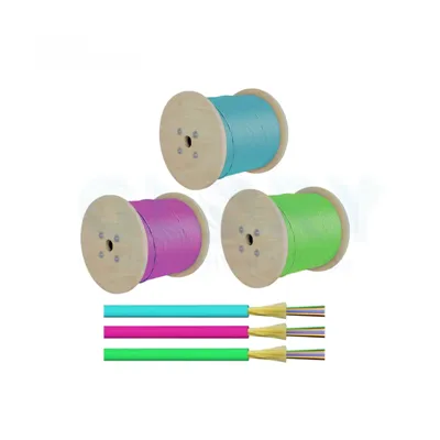
Outdoor Armored Direct Burial Cable - For Groundwater & Seasonal Flooding
Loose-tube gel-filled or dry water-blocked design with corrugated steel tape armor, bonded dual PE jacket, and FRP or steel central strength member. Available 2–144 fibers in G.652.D or G.657.A1. Rated for direct burial in normal and aggressive soils; survives temporary submersion during flooding events. Standard depths 0.6–1.2 m. Batch-tested to IEC 60794 including E12 water penetration.
View Armored Direct Burial CableOutdoor OSP Loose-Tube Cable - Base for Conduit-in-Water Crossings
Glory's standard outdoor OSP cable line in GYTS, GYXTW, and GYFTY constructions covers the highest-volume direct burial and conduit applications. For pond and lake crossings using the HDD + conduit method, this cable goes inside the HDPE conduit - the conduit provides the mechanical and waterproofing function; the cable provides optical capacity. Available 6–288 fibers, G.652.D / G.657.A1, HDPE or LSZH jacket options.
View Outdoor OSP CableFTTH Drop Cable - For Shore-Side Entry and Short Rural Drops
For the last-drop segment connecting a water-crossing cable to a subscriber premises, Glory's G.657.A2 FTTH drop cables handle the final bend-intensive indoor section. Self-support and figure-8 options for aerial drop; dielectric designs for conduit. Pairs with the subaqueous cable at an IP68 dome closure at the shore entry point. Available SC/APC pre-terminated or factory-bare for field connectorization.
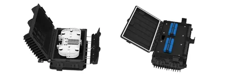
View FTTH Drop CablesIP68 Dome Splice Closures - Required at Every Shore Entry Point
The splice closure at a shore entry or waterside handhole must be IP68-rated - not IP67, not IP55. Glory's dome splice closures for water-crossing applications are rated IP68 at 3 m sustained, with adjustable compression cable port seals covering 8–16 mm OD cables and heat-shrink port options for smaller diameters. Tray configurations for 24–144 splices. Available in single-cable entry and multi-cable entry configurations for pond crossing + distribution network architectures.
View IP68 Splice ClosuresFiber Patch Cords & Pigtails - For Equipment-Side Termination
Once the crossing cable is terminated in the shore-side splice closure and connected to the network, the equipment-side connection uses standard fiber patch cords. SC/APC and LC/APC in G.657.A2, 2.0 mm duplex. Per-batch factory tested to IEC 61300-3-35 (IL) and IEC 61300-3-6 (RL). LSZH jacket for any indoor or riser environment adjacent to the crossing.
View Patch CordsPLC Splitters - For Distribution Network Design at the Shore-Side Closure
Water crossings that serve multiple subscribers on the far shore often include a PLC splitter at the shore-side handhole, distributing one feeder fiber to multiple drop cables. Glory's 1×4 through 1×32 PLC splitters in packaged and bare-fiber form fit inside IP68 dome closures for waterside distribution nodes. 28 dB GPON Class B+ loss-budget compatible at 1×32 split.
View PLC SplittersNeed a custom inland waterway cable specification - specific fiber count, armor configuration, jacket color, or HDPE conduit pre-loaded into a single reel product? Glory Optical's OEM/ODM program supports custom water-crossing cable assemblies, pre-assembled shore-entry kits with IP68 dome closure and cable grip, and private-label packaging with per-batch test documentation. Lead times from 20 working days for prototypes; full production from 45 days. Learn about OEM / ODM services →