Engineering Review Basis
This guide was reviewed for connector-format compatibility, polarity and lane mapping, per-link loss budget, field tooling fit and BOM feasibility. The intent is practical design review: identify where MMC creates a real density advantage, where MPO/MTP remains the safer default, and which parameters a supplier needs before quotation. Final channel-loss limits still come from the selected transceiver and component datasheets.
The 60-Second Decision Answer
For most 400G/800G data center projects, MPO/MTP should remain the default for trunks, backbones and structured patching. MMC becomes attractive when the real constraint is panel density, not when the project simply needs another connector option. The lowest-risk path is usually hybrid: keep the existing MPO/MTP plant, then introduce MMC only in new high-density patching zones with the right adapters, transition assemblies, cleaning tools and test method.
| Decision factor | Recommended starting point | Approval focus |
|---|---|---|
| Backbone & trunks | MPO/MTP on OS2, OM4 or OM5, with base and fiber count selected from the transceiver PMD | Connector grade, polarity method, channel budget, trunk length, cassette count and acceptance-test report |
| Ultra-high-density patching | Evaluate MMC only where panel space per RU is the limiting constraint | Port access, bend radius, labeling clarity, VSFF cleaning tip availability and test-adapter availability |
| Loss budget | Approve the link by total channel loss, not by connector density | Every mated pair, adapter, cassette, transition assembly, trunk attenuation and reserved margin |
| Migration risk | Use MMC-to-MPO/MTP transition assemblies instead of a full connector swap in existing sites | Where each format hand-off occurs, how it is labeled, and how polarity is documented on both sides |
| Field operation | Plan tooling as part of the connector-format decision | Cleaning sticks, inspection probes, launch cords, adapters, IL/RL test process and technician training |
MMC should be evaluated as a high-density design option, not as a universal replacement for every MPO/MTP connection. Use it where panel space is the constraint and the project can support the matching adapters, transition assemblies and field workflow. For most brownfield sites, a hybrid layout protects the existing trunk plant while solving density pressure only where it occurs.
Why Connector Choice Matters in 400G/800G Data Centers
At 400G and 800G, the connector decision is not isolated from the rest of the optical channel. The optic type, lane count, reach category, fiber type, panel layout, cassette count and operating procedure all influence whether a link is buildable and maintainable. A connector that improves port density can still be the wrong choice if it adds unmanaged transition points or cannot be cleaned and tested in the installed position.
AI data centers and GPU cluster fabrics intensify the issue because they concentrate more high-speed links into smaller patching zones. The pressure is usually felt in four places: rack and panel space, bend-radius control, link-loss margin and the amount of documentation required to trace parallel lanes. For that reason, the practical question is not simply what is MMC? or is MPO/MTP outdated? The useful question is: which connector format reduces the real project constraint without creating a larger operations risk?

This article focuses on the connector decision for structured fiber cabling. The wider design context - transceiver-to-fiber mapping, MTP/MPO base selection, OS2 backbone planning and acceptance testing - is covered in our AI data center fiber cabling guide. Treat the two together: the cabling design decides the connector, and the connector decides the BOM.
What Are MPO/MTP Connectors?
MPO (Multi-fiber Push-On) is the established multi-fiber connector family for parallel optics in data centers. A single MPO ferrule holds a linear fiber array, which is why MPO-based assemblies are widely used in trunk cables, MPO-to-LC cassettes, patch panels, parallel-optic transceiver modules and breakout cabling. The interface is standardized under the IEC 61754-7 series and TIA-604-5 / FOCIS 5, which is the basis for compliant MPO-family intermateability.
MTP is a registered trademark of US Conec for an enhanced MPO connector with tighter controlled design features. In procurement language, it is useful to keep the terms distinct: every MTP is an MPO-format connector, but not every MPO connector is an MTP connector. MTP-grade assemblies are often specified where low-loss performance, repeatability and multi-panel channels matter. For a deeper treatment of this distinction, see our MTP vs MPO engineering differences guide.
For 400G/800G links, do not choose the fiber count from the connector name alone. Common MPO configurations include 8, 12, 16 and 24 fibers, but the correct base depends on the transceiver PMD, lane rate, reach category and switch front-panel design. Some parallel-optic applications may require MPO-16, while others use dual MPO-12, MPO-12 breakout, LC breakout or another vendor-specific mapping. Start with the transceiver datasheet, then specify the MPO/MTP base, polarity and lane map.
| Item | Description |
|---|---|
| Connector type | Multi-fiber connector (linear fiber array in an MT-style ferrule) |
| Common fiber counts | 8F, 12F, 16F, 24F (higher counts for specialty applications) |
| Typical use | Trunks, MPO-to-LC cassettes, patch panels, breakout links, parallel-optic modules |
| Main advantage | Mature ecosystem, broad compatibility, familiar testing and documentation |
| Main limitation | Density and cable-management pressure in ultra-high-density zones |
What Is an MMC Connector?
MMC is a very small form factor (VSFF) multi-fiber connector developed by US Conec for high-density optical connectivity. Its main value is packaging more fibers into less front-panel space. US Conec describes the format as combining a reduced-size TMT ferrule with a compact VSFF connector body for high-density data center and optical interconnect applications.
The TMT ferrule is built on the MT and MT-16 alignment family used in MPO and MPO-16, and MMC is offered in multi-fiber variants for single-mode and multimode applications. Vendor-published material from Fujikura, a licensed MMC manufacturer, states that the format can deliver roughly three times the cabling port density of MPO in selected panel designs. Treat that figure as a vendor-published density claim, not as a universal number for every rack, panel or cable-management layout.
MMC is not a drop-in substitute for every MPO/MTP link. It uses a different connector housing, different adapters and format-specific cleaning and inspection accessories. Its supply ecosystem is growing, but it remains narrower than the long-established MPO/MTP base. In a practical 400G/800G project, MMC should be selected only when the density gain is large enough to justify the extra planning around adapters, transition assemblies, polarity documentation and field tooling.
Treat MMC as a targeted density tool. It is most valuable when the panel face is the bottleneck and the new zone can be designed around MMC adapters, service access and transition assemblies from the start. If the limiting factor is transceiver budget, cleaning discipline or supply-chain standardization, higher connector density alone does not solve the project risk.
MMC vs MPO/MTP: Key Differences at a Glance
The table below summarizes the practical trade-offs. Read it as a decision aid, not a verdict - the right choice depends on which factor is binding in your project.
| Factor | MPO/MTP | MMC |
|---|---|---|
| Connector category | Multi-fiber connector (MT-style ferrule) | VSFF multi-fiber connector (TMT ferrule) |
| Market maturity | Very mature, broad multi-vendor base | Newer / emerging, growing ecosystem |
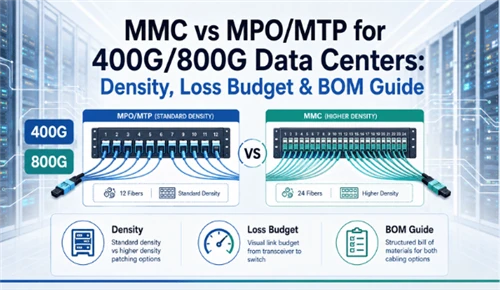
| Density | High | Higher than MPO/MTP (vendors cite ~3x port density) |
| Typical role | Backbone trunks, cassettes, patch panels, breakout | Ultra-high-density patching and future-ready zones |
| Migration difficulty | Low in existing systems | Requires planning (panels, polarity, tooling) |
| Testing familiarity | High; well-understood field workflow | Depends on available tools and trained process |
| Supply chain | Broad and mature | Growing, multi-source agreements expanding |
| Best fit | Standard 400G/800G structured cabling | Space-constrained, high-density designs |
Important: MMC and MPO/MTP Are Not Directly Intermateable
MMC and MPO/MTP connectors use different housings and cannot be plugged directly into each other, even though the TMT ferrule inside MMC shares the MT alignment geometry with the MPO ferrule. Do not treat MMC as a drop-in replacement for MPO/MTP without changing adapter panels, cleaning tools and test tooling.
- No direct intermateability. An MPO adapter does not accept an MMC connector; an MMC adapter does not accept an MPO/MTP connector. Format mixing at an adapter will produce a non-functional connection.
- Transition assemblies are required. Every point where the two formats meet within a link requires a dedicated transition assembly: MMC-to-MPO, MMC-to-MTP or MMC-to-LC. These are specific products, not field-improvised adaptations.
- Plan and budget every transition point. Each transition assembly adds a component, a mated pair and a loss contribution to the channel. Identify each transition point in the design, include it in the BOM and account for it in the loss budget before approving the design.
- Adapter panels, cleaning tools and test adapters all change. Replacing patch cords alone will not bridge the two formats. Adopting MMC in a patching zone requires MMC adapters, a VSFF-compatible cleaning kit and an MMC test adapter - not MPO/MTP equivalents used with an adapter.
Density Comparison: Where MMC Has an Advantage
MMC's advantage shows up most clearly in patch panel and port density. Vendor-published figures from Fujikura and US Conec position MMC at approximately 3× the cabling port density of comparable MPO designs. Exact per-RU counts still depend on the panel, fiber count and cable-management architecture, so treat density figures as product-family examples rather than universal rules. For AI clusters, leaf-spine fabrics, DCI handoffs and dedicated high-density patching zones, that density advantage can determine whether a fabric fits within the available cabinet count.
As a practical reference point, conventional 1U MPO-12 layouts are often evaluated around a 72-port / 864-fiber class, depending on cassette and panel design. Fujikura publishes an MMC-16 example of up to 3,456 fibers in 1RU, while a US Conec MMC brochure gives a 12-fiber MMC example of 264 MMC ports / 3,168 fibers in 1RU. That is the concrete meaning behind the approximate 3× density claim: fewer rack units for the same optical port count, or more available port capacity in the same rack space.
But density is only useful when the cabling stays maintainable. The denser the panel, the more these practical factors matter: bend radius and fiber routing, clear labeling, physical access for cleaning, service-loop length, and the ability to trace a single port without disturbing its neighbors. A panel that doubles port count but makes a single connector impossible to clean or re-trace has traded an operations problem for a density number.

A high-density panel is useful only if the ports remain serviceable. In the design review, check whether a technician can access and clean one port without disturbing adjacent patch cords, whether labels remain readable after full loading, and whether service loops can be managed without violating bend radius. Density that cannot be maintained in the field becomes a failure mode rather than a benefit.
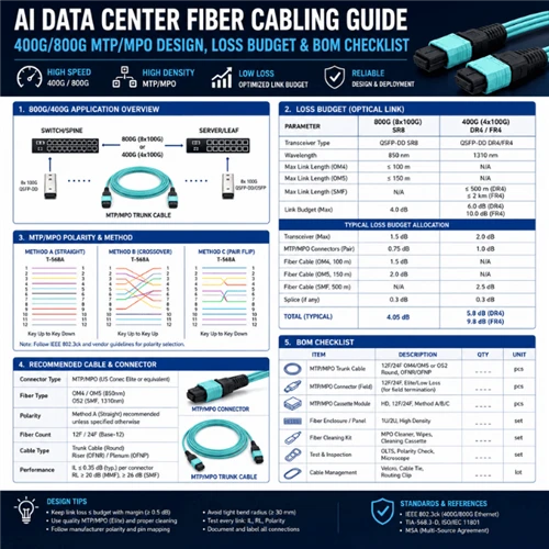
Loss Budget Planning for 400G/800G Links
Connector choice should be approved by the total channel budget, not by the connector format alone. Every mated pair, adapter, cassette, transition assembly and meter of fiber consumes part of the available margin. At 400G/800G, a single additional transition point, a contaminated end face or an unplanned cassette can change the link from pass to fail.
For MPO/MTP, the advantage is operational maturity: low-loss grades, polarity methods, cassettes, cleaning tools and field-test workflows are familiar to most installers. For MMC, the planning task is to record the selected product's insertion loss, return loss, end-face requirements and test-adapter availability in the BOM. Neither format is automatically low-loss; the actual result depends on component grade, cleanliness, polish, reference method and how many interfaces the design creates.
Start from the transceiver vendor's maximum channel insertion loss and required interface mapping, then work backward through the cabling plant. This prevents a common mistake: choosing MPO-16, dual MPO-12, MMC transition assemblies or LC breakout by panel preference before the optic type and lane map are known. Once the optic is fixed, the connector format becomes a channel-design decision, not a standalone product choice.

Loss budget checklist
Work the budget item by item for every link type before approving a connector or a BOM:
- Transceiver interface - start with PMD, lane count, reach category and maximum channel insertion loss.
- Connector mated pairs - count every pair in the channel and assign a planned per-pair loss from the component grade.
- Adapter and cassette interfaces - include panel adapters, cassette interfaces and transition modules separately.
- Transition assemblies - add MMC-to-MPO/MTP, MMC-to-LC or MPO-to-LC assemblies as explicit loss items, not as hidden accessories.
- Trunk fiber attenuation - calculate from the deployed fiber type and measured route length, including service loops where relevant.
- Cleaning and contamination risk - reserve handling margin and include format-matched cleaning accessories in the project kit.
- Test reference method - define IL, RL, polarity, end-face and OTDR requirements before installation begins.
- Design margin - document the minimum reserved margin per link type and reject designs that rely on a zero-margin pass.
For parallel single-mode optics, verify reflectance and connector polish, not just insertion loss. A link can pass on loss and still fail on return loss if the polish or end-face condition is wrong. Our fiber connector cleaning and inspection process guide covers the end-face workflow that protects the budget you planned.
Example: 800G Link Budget Review Before Connector Approval
The table below is a review worksheet, not a universal design value table. Insert values from the transceiver specification, component datasheets and project route measurements. The purpose is to expose every loss item before a connector format or BOM is approved.
| Review item | Planning input | Approval note |
|---|---|---|
| Transceiver channel budget ceiling | Per transceiver datasheet | Use the specific optic type and reach category; do not copy a value from another 800G application. |
| Interface mapping | MPO-16 / dual MPO-12 / LC breakout / MMC transition / other | Confirm the lane map before ordering patch cords, cassettes or transition assemblies. |
| Near-end patching interfaces | [number of mated pairs × planned per-pair loss] | Record connector grade and verify end-face condition during acceptance testing. |
| Cassette or transition assembly | [if applicable] | Add MPO-to-LC, MMC-to-MPO/MTP or MMC-to-LC assemblies as separate channel elements. |
| Trunk fiber attenuation | [fiber type × measured route length] | Use actual installed length where available; include service loops and route slack. |
| Far-end patching interfaces | [number of mated pairs × planned per-pair loss] | Verify far-end inspection and cleaning records separately from the near end. |
| Reserved design margin | [project-specific minimum] | Reserve for re-patching, contamination, documentation errors and future changes. |
| Required evidence | IL / RL / polarity / end-face / OTDR where required | Define the report package in the BOM so the supplier and installer quote the same deliverables. |
Migration Path: From MPO/MTP Infrastructure to MMC
Most projects are not greenfield, so the realistic question is how MMC enters an environment that already runs MPO/MTP. There are three sensible paths, and the right one depends on how much density pressure exists and how much risk the project can absorb.

BOM Checklist by Project Scenario
A useful 400G/800G BOM is not just a list of cable names. It must show how each assembly fits the channel: connector format at both ends, fiber count, polarity, length, quantity, spare ratio, label format and required test evidence. The scenarios below help buyers choose the right component family before converting the design into a quotation-ready worksheet.
Before a quotation is accurate, the supplier should be able to check format compatibility, connector gender and polish, fiber count, polarity method, trunk length, panel density, label scheme, packaging requirement and required test evidence. If any of these items are missing, the quote may be fast but the order will usually require revision before production.
Information buyers should provide
To turn the design into a buildable assembly list, provide the following before requesting a quotation:
| Parameter | What to specify |
|---|---|
| Data rate | 400G / 800G / future 1.6T |
| Fiber type | OM4 / OM5 / OS2, with reach expectation |
| Connector type | MMC / MPO / MTP / LC, including side A and side B |
| Fiber count | Per assembly, such as 8F, 12F, 16F or 24F |
| Rack count | Number of racks, rows and patching zones |
| Link distance | Per route, including service loop and routing allowance |
| Switch model | Front-panel port type, port count and platform generation |
| Transceiver type | PMD / reach / lane mapping, such as SR, DR, FR, LR, DR4 or DR8 |
| Polarity requirement | Method, lane map and document version |
| Panel density requirement | Ports per RU, 1U or 2U preference, cable-management limits |
| Test report requirement | IL, RL, polarity, end-face inspection and OTDR where required |
| Packaging & labeling | Port label, link ID, carton label, batch number and project code |
Quotation-Ready BOM Worksheet
Use a worksheet format when sending the project to a supplier. This reduces back-and-forth because each cable or panel line item contains both the product requirement and the verification requirement.
| BOM field | Example input | Why it matters |
|---|---|---|
| Assembly type | MTP/MPO trunk, MMC-to-MPO transition, MMC patch cord, MPO cassette | Prevents quoting the right connector family in the wrong assembly format. |
| Connector side A / side B | MMC APC to MPO-16 APC; MTP female to MTP female; MPO to LC breakout | Controls adapter compatibility, gender planning and transition points. |
| Fiber count and fiber type | 12F / 16F / 24F; OS2 / OM4 / OM5 | Must match the optic mapping and reach plan. |
| Polarity / lane map | Method A / B / C or project-defined map | Wrong polarity can make an otherwise correct BOM unusable at commissioning. |
| Length and route | Cabinet A03 to row B spine panel, 18 m plus service loop | Supports manufacturing length, labeling and loss calculation. |
| Quantity and spare ratio | 48 links + 6 spares, or project-specific spare policy | Prevents under-ordering and makes lead-time risk visible. |
| Required test evidence | IL/RL report, polarity report, end-face images, OTDR where required | Aligns factory QC, installation acceptance and handover documentation. |
| Label and packaging rule | Link ID on both ends, carton label by rack zone, batch number recorded | Reduces installation errors and supports later troubleshooting. |
When Should You Choose MMC?
Choose MMC when the project has a measurable density problem and the operations team can support the format. The strongest use cases are:
- Ultra-high-density patching zones where ports per RU is the limiting factor
- New AI cluster or leaf-spine areas where the cabling architecture can be designed around MMC from day one
- Space-constrained cabinets where adding more MPO/MTP panels is not practical
- Forward-looking 800G / 1.6T planning where panel capacity must be protected
- High-density optical interconnect areas where compatible adapters, cleaning and testing are already planned
Do not choose MMC only because it is newer or smaller. Use it where density changes the rack plan; stay with MPO/MTP where standardization, field familiarity and supply-chain depth matter more than saving panel space.
When Should You Stay With MPO/MTP?
MPO/MTP remains the right default when the project depends on repeatability, supply-chain depth and predictable field execution. Stay with MPO/MTP when the design involves:
- 400G/800G backbone cabling
- MTP/MPO trunk cable systems
- Cassette-based structured cabling
- Standard data center patch panel deployment
- Upgrades to documented existing infrastructure
- Projects that require mature testing, cleaning and documentation workflows
This is not a conservative compromise. Across hundreds of repetitive links, a familiar connector ecosystem can reduce installation risk more than a higher-density connector can reduce panel count.
Practical Design Recommendations
Use the following checklist before approving a connector format or supplier BOM:
- Start from the transceiver PMD and channel-loss ceiling.
- Do not compare MMC and MPO/MTP by density alone.
- Count every mated pair, cassette, adapter and transition assembly.
- Document polarity and lane mapping before ordering assemblies.
- Include cleaning sticks, inspection tips and test adapters for the chosen format.
- Define IL, RL, end-face, polarity and OTDR evidence requirements in the BOM.
- Reserve spare ports, spare assemblies and a minimum design margin.
- Use hybrid cabling when density is needed locally but MPO/MTP compatibility remains important.
Recommended Categories for 400G/800G Fiber Cabling
Map product categories to the design layer instead of ordering by connector name alone. Each category should be checked against connector format, fiber count, polarity, length, panel density, cleaning tools and test-report requirements.
| Design layer | Typical components | Procurement check |
|---|---|---|
| Backbone / trunks | Base-8, Base-12, Base-16, MPO-12, MPO-16 and MTP/MPO trunk assemblies | Fiber type, trunk length, polarity, connector grade and factory test report |
| Transition layer | MMC-to-MPO, MMC-to-MTP and MMC-to-LC transition assemblies | Side A / side B format, lane map, added loss and transition-point labeling |
| Patching layer | 1U/2U high-density patch panels, adapter panels, MPO cassettes and cable managers | Port access, service-loop space, cable routing and cleaning access |
| Testing & maintenance | Cleaning tools, inspection tips, test adapters and IL/RL / end-face report package | Format compatibility and technician workflow before installation |
MTP/MPO Trunk Cables
Base-8, Base-12, Base-16, MPO-12 and MPO-16 assemblies for structured 400G/800G links, with fiber type, polarity and test reports defined per project.
View MTP/MPOMMC / MPO / LC Transition Assemblies
Transition cable planning for hybrid designs where MMC high-density patching connects back to MPO/MTP backbone or LC equipment interfaces.
Request Transition BOMHigh-Density Fiber Patch Panels
1U/2U patch panels, MPO cassettes, adapter panels and cable-management options for dense 400G/800G patching zones.
View Patch PanelsCertificates & Test Documentation
CE, RoHS, ISO 9001 and batch-level test documentation guidance for procurement teams that need supplier validation before project approval.
Read Certification GuideFAQ: MMC vs MPO/MTP for 400G/800G Cabling
-
Q: Is MMC better than MPO/MTP?
A: Neither connector is universally better. MMC is a very small form factor (VSFF) connector built for density, so it fits more ports into the same panel space than MPO/MTP and is attractive where panel space is the binding constraint. MPO/MTP remains the more mature choice for most structured cabling, with a broad supply chain, familiar field testing and proven cassette and trunk ecosystems. The right answer depends on density pressure, loss budget, migration cost and the maintenance capability of the on-site team.
Q: Can MMC replace MPO/MTP in existing data centers?
A: MMC can be introduced in selected high-density zones rather than swapped in wholesale. Before any replacement, review panel design, polarity mapping, the per-link loss budget, available cleaning and inspection tools, and your test process. For most existing sites, a hybrid path that keeps the MPO/MTP backbone and adds MMC only where density demands it is more practical than a full migration.
Q: Is MPO/MTP still suitable for 800G cabling?
A: Yes. MPO/MTP is still well suited to 400G and 800G structured cabling, especially for trunks, cassettes, patch panels and breakout applications. For 800G the relevant question is usually which base to use, such as MPO-16 or dual MPO-12 depending on the transceiver, rather than whether to abandon MPO/MTP altogether.
Q: What should be included in a 400G/800G fiber cabling BOM?
A: A complete BOM should cover trunk cables, patch cords, patch panels and cassettes, adapters, breakout cables, cleaning and inspection tools, test reports, a labeling plan and polarity documentation. For each item, record the data rate, fiber type, connector type and fiber count, polish and gender, link distance, panel density and the required test evidence.
Q: When should a data center consider MMC connectors?
A: Consider MMC when panel space, port density or future scalability become the main constraint, typically in new-build AI data centers, ultra-high-density patching zones, space-constrained cabinets, or forward-looking 800G and 1.6T planning. Where the existing MPO/MTP system is mature, supply-chain stability matters most, or the field team has limited MMC cleaning and testing experience, MPO/MTP is usually the safer default.
Q: Are MMC and MPO/MTP connectors intermateable?
A: No. MMC and MPO/MTP are different connector formats and do not plug into each other directly. To bridge the two, use a transition assembly such as an MMC-to-MPO or MMC-to-MTP cable, or break out to LC with an MMC-to-LC assembly. The TMT ferrule used in MMC is based on the same MT and MT-16 alignment family as MPO, but the connector housings are not interchangeable.
Q: Do MMC connectors need different cleaning and testing tools?
A: Plan for format-specific tooling. Because MMC uses a smaller VSFF housing and a denser end face, the cleaning sticks, inspection tips and test adapters that fit MPO/MTP will not necessarily fit MMC. Include compatible cleaning, end-face inspection and insertion-loss / return-loss test tools in the MMC deployment kit, and train the on-site team on the format.
Q: Does MMC reduce insertion loss compared with MPO/MTP?
A: Not necessarily. The connector format is not the sole determinant of insertion loss. Actual insertion loss depends on component grade, ferrule end-face quality, polish type, cleanliness at the time of connection, the number of mated pairs in the channel and the test reference method. A higher-density connector is not automatically a lower-loss connector. Use the specific product datasheet for insertion-loss and return-loss limits, and inspect end-face condition before link acceptance.
Q: What is the safest migration path from MPO/MTP to MMC?
A: For most existing data centers, the safest route is a hybrid design: retain the MPO/MTP backbone, trunk cables and cassette infrastructure, and introduce MMC only in new high-density patching zones where density is the binding constraint. Connect the two sides using MMC-to-MPO or MMC-to-MTP transition assemblies. This approach limits the scope of change - polarity, adapter panels, tooling and test procedures only change at the transition points, not across the whole plant.
Standards, Public Sources and Further Reading
The references below support connector definitions, standard interfaces, density examples and testing context used in this guide.
- US Conec - MMC Connectors - MMC as a VSFF multi-fiber connector using TMT ferrule technology harmonized with the MT / MT-16 alignment structure.
- US Conec - MMC Connector Solutions brochure - public MMC density example showing 264 MMC ports / 3,168 fibers in 1RU using 12-fiber MMC.
- Fujikura - MMC Connector Solutions - licensed MMC manufacturer reference for MMC density positioning and per-RU fiber-count examples.
- IEC 61754-7 series - interface dimensions for the type MPO family of connectors. TIA-604-5 / FOCIS 5 covers corresponding US requirements where applicable.
- Fluke Networks - Multi-fiber Push-On (MPO) Connectors - MPO fiber-count overview and inspection / cleaning considerations.
- VIAVI Solutions - What Is MPO Connector Testing? - MPO testing context, including Tier 1 / Tier 2 installed-link acceptance concepts.
- Lightwave - US Conec, Hakusan and Sanwa multi-source MMC / TMT agreements - public reference for the expanding MMC VSFF supply ecosystem.
Technical review: Data Center Cabling Product Engineer, Glory Optical. Review scope: connector selection criteria, polarity mapping conventions, loss-budget planning and supplier-ready BOM structure for 400G/800G projects. This guide supports design and procurement decisions for high-density fiber cabling; final insertion-loss, return-loss and density values belong in the approved component datasheets and project acceptance criteria.
About Glory Optical: Ningbo Glory Optical Communication Co., Ltd. supplies data center cabling and passive optical components including MTP/MPO trunk cables, fiber patch panels, indoor fiber optic cables, fiber boxes, ODN components, pigtails and patch cords. For 400G/800G and AI data center projects, send your transceiver list, rack layout and connector preference for BOM mapping and loss-budget review.