The Quick Answer
Choose an MST by working backward from three field facts: how many drops the location must serve over its lifetime, which hardened connector your drop cables use, and the environmental exposure of the mounting point. An MST (multiport service terminal) is a sealed, pre-connectorized distribution terminal with several weatherproof ports that let a technician plug in a subscriber drop with no splicing and no opening the box. Match the port count to homes passed plus a take-rate margin (4–6 ports for sparse aerial runs, 8 for the suburban default, 12–16 for dense MDUs); specify a hardened connector that matches your drop ecosystem (OptiTap-style SC/APC is the most common); and confirm the sealing rating against where it sits - IP65 for sheltered aerial, IP68 for buried or flood-prone handholes.
The rest of this guide turns each decision into a practical buyer checklist: compare MSTs against splice closures and distribution boxes, choose port count and connector ecosystem, map IP rating to the mounting environment, verify the splitter loss budget, and request the right supplier documents before approval.
MST Selection Checklist: From Field Scenario to Specification
If you only need a purchase-order specification, use the checklist below. It keeps the decision sequence focused on the factors that usually decide whether an MST deployment works in the field: served homes, connector compatibility, environmental exposure, optical budget, stub length, and documentation.
Start with every home, unit, or business inside the practical drop radius. Apply the expected take rate over the terminal's service life, then add one or two spare ports before rounding up to 4, 6, 8, 12, or 16 ports.
The MST port, drop cable, field plug, adapter cap, and polish type must match. For FTTH, the common single-fiber choice is a hardened SC/APC ecosystem, but vendor shell geometries are not automatically cross-matable.
Use sheltered aerial/pole, exposed pedestal, buried handhole, or flood-prone vault as the first decision. IP68 should include the stated depth and duration in the supplier datasheet, not just the label "IP68".
Choose an integrated splitter terminal when the split point should sit near subscribers. Choose a breakout MST when splitting happens upstream at a cabinet, FDH, or distribution point.
Order the stub length to the actual span and slack-storage plan. A short stub creates an unplanned splice; an overlong stub creates bend-radius and storage problems at the terminal.
Ask for the datasheet, port map, connector interface drawing, insertion-loss/return-loss report, IP sealing statement, packing list, and installation manual for the exact configuration you intend to buy.
Low-density aerial: 4 or 6 ports, IP65/IP67, breakout or 1:4 split. Suburban FTTH: 8 ports, hardened SC/APC, IP67, integrated 1:8 or upstream split depending on ODN design. Dense MDU or urban cluster: 12 or 16 ports, stricter port labeling, splitter-loss check, and documented slack management. Handhole or flood-prone route: IP68 with stated immersion condition and cap audit procedure.
MST at a Glance
Before the detail, here is the device in one table - what an MST is, the configuration choices you actually specify, and the standards that govern each one. Use it as the skeleton of a tender line item.
| Attribute | What it means | Typical options |
|---|---|---|
| Function | Breaks a feeder or splitter output into plug-and-play drop ports | Distribution / drop terminal in the ODN |
| Port count | Number of hardened drop ports on the body | 4, 6, 8, 12, 16 |
| Output connector | Hardened, outdoor-rated mating interface | OptiTap-style SC/APC; hardened MPO for multi-fiber |
| Splitter | Whether a PLC splitter sits inside the body | Integrated 1:8 / 1:16, or non-split breakout |
| Sealing | Ingress protection for the mounting environment | IP65 / IP67 / IP68 per IEC 60529 |
| Mounting | How the terminal is fixed in the field | Aerial / strand, pole, pedestal, wall, handhole |
| Stub / pigtail | Pre-terminated feeder tail and its length | Specify length and connector to suit the span |
| Reference standards | Frameworks a datasheet should map to | IEC 60529, IEC 61753, ITU-T G.671, Telcordia GR-3120 |
1. What Is an MST Multiport Service Terminal?
An MST is a hardened, environmentally sealed terminal in the optical distribution network (ODN) that converts a single feeder or splitter input into multiple weatherproof drop ports. Each port is built on a hardened connector, so a field technician connects a subscriber by plugging a pre-connectorized drop cable straight into the port - no fusion splicer, no enclosure opening, no re-sealing. That single design choice is the whole point of the product: it moves the slow, skilled work (splicing, splitting) back to a cabinet or factory and leaves the field task as a clean plug-in.
The category goes by several names - multiport drop terminal, multiport tap, FTTH access terminal - and you will also see the OptiTap-compatible fiber access terminal framing when the emphasis is on connector ecosystem. When a PLC splitter is built into the sealed body, the same device is sold as a multiport splitter terminal. Functionally they are one device class with two internal configurations, covered in Section 6.
What sits inside
A typical MST contains a sealed housing; a feeder entry (a pre-terminated stub, or a gland for a field-prepared cable); either an internal splitter or a set of factory-terminated fibers; and the rear of each hardened output port. Because the body is sealed at the factory, the internal fiber management and the port count are fixed for the life of the unit - a constraint that drives the sizing logic in Section 3.
OLT → feeder cable → (splitter, at a cabinet or inside the MST) → MST drop ports → drop cable → subscriber ONT. The MST is the last passive distribution point before the customer premises - the spot where the network meets the street.
2. When Should You Use an MST Instead of a Splice Closure or Fiber Distribution Box?
All three live at roughly the same place in the access network, so the choice is about how you connect subscribers, not where. The deciding factors are connection speed, the skill level on the truck, and the cost you are optimising - hardware versus labour.
| Factor | MST | Splice closure | Fiber distribution box / access terminal |
|---|---|---|---|
| Subscriber connection | Plug-and-play hardened port | Fusion splice each fiber | Patch via internal adapter, or splice a pigtail |
| Splicing in the field | None for drops | Required | Often required (pigtails) |
| Enclosure opened per drop | No | Yes | Yes |
| Skill level on site | Low - connect and seat | High - trained splicer | Medium |
| Time to add a subscriber | Minutes | Longer (splice + reseal) | Moderate |
| Houses a splitter | Optional (integrated) | Sometimes | Commonly |
| Per-port hardware cost | Higher | Lower | Lower to moderate |
| Best for | Fast drops, high churn, lean crews | Feeder / distribution joints | Patching, splitter housing, frequent reconfig |
A simple rule
Reach for an MST when the dominant cost in your build is field labour and truck rolls, when connection speed and mean time to repair matter, and when you want to keep crews lean and less specialized. Reach for a splice closure or distribution enclosure when you are joining feeder or distribution fibers mid-span, when you need adapter-based patching and reconfiguration, or when per-port hardware cost dominates your model and you have splicing capacity to spare. Most real networks use both: closures and cabinets upstream, MSTs at the street-facing edge.
3. How to Choose MST Port Count: 4, 6, 8, 12 or 16 Ports
This is the decision people get wrong most often, in both directions. Because an MST's ports are sealed and fixed, under-porting forces a full terminal swap - a second truck roll and a service interruption - the moment take rate climbs past your installed ports. Over-porting wastes capital on unused ports and, if the terminal has an integrated splitter, burns optical budget on splitter loss you never use.
The sizing method
- Count homes passed within the terminal's practical drop radius (set by your maximum economical drop length).
- Apply expected take rate over the terminal's life - not today's subscriber count. A 60% long-term take rate on 10 homes passed is 6 active drops.
- Add spare ports for growth, churn re-connects, and the occasional bad port. One to two spares is typical.
- Round up to a standard size - 4, 6, 8, 12, or 16.
| Port count | Common feed / split | Best deployment | Notes |
|---|---|---|---|
| 4 | 1:4 split or 4-fiber breakout | Sparse rural, ribbon ends, MDU sub-floors | Lowest cost; little headroom - size carefully |
| 6 | 6-fiber breakout | Low-density aerial, small clusters | A middle step where 4 is tight and 8 is wasteful |
| 8 | 1:8 split | Suburban aerial - the common default | Best balance of coverage and spare capacity |
| 12 | 12-fiber breakout | Denser streets, small MDUs | Fewer terminals per route; check drop management |
| 16 | 1:16 split | Dense MDUs, urban clusters, garden apartments | Highest density; confirm loss budget at 1:16 |
Size for the network's life, not its launch. The cost of one spare port on day one is a rounding error next to the cost of a terminal swap and a second crew visit when a street fills up. When in doubt, go one size larger - unless an integrated splitter's loss at that ratio would break the reach.
4. Hardened Connector Options
The hardened connector is what makes an MST an MST - a standard SC connector is not rated to sit exposed on a pole and mate outdoors. Hardened (ruggedized) connectors add a sealed, latching shell around a familiar ferrule so the mated joint survives weather, UV, and handling. The options you will meet:
- OptiTap-style hardened SC/APC - the most widely deployed single-fiber hardened interface, built on a 2.5 mm SC/APC ferrule inside a sealed bayonet or threaded shell. It is the default for single-fiber FTTH drops and the reason "OptiTap-compatible" appears on so many terminals and drop cables.
- Hardened MPO - for multi-fiber drops (for example, feeding an MDU riser or a small business with several fibers from one port).
- Other hardened single-fiber systems - several vendor ecosystems exist with their own shell geometry. They are not cross-matable with OptiTap-style hardware.
Match the ecosystem end to end. The terminal port, the pre-connectorized drop cable, and any field-installed hardened plug must share the same hardened format and the same polish (almost always APC for FTTH). A mismatch is the most common reason a drop will not seat or will not seal - and a sealing failure is an IP failure waiting for the first rain.
If you are unsure which connector family your existing drop inventory uses, our connector comparison guide covers ferrule sizes and APC versus UPC polish, which is the detail that most often trips up a mixed-vendor build.
5. IP Rating and Environmental Sealing
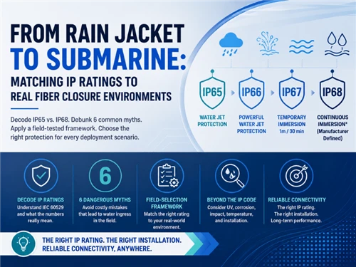
An MST lives outdoors for years, so its ingress protection rating - summarized by the IEC IP rating overview and formally defined by IEC 60529 - is a specification, not a marketing badge. The rating is two digits: the first is solids/dust, the second is water. Match it to the mounting environment rather than buying the highest number by reflex.
| IP rating | Water protection (IEC 60529) | Typical use |
|---|---|---|
| IP65 | Dust-tight; protected against low-pressure water jets | Sheltered aerial, pole, under-eave wall mounting |
| IP67 | Dust-tight; temporary immersion to ~1 m | Exposed aerial, pedestal, surface boxes |
| IP68 | Dust-tight; continuous immersion to a stated depth | Buried handholes, flood-prone vaults, below-grade |
The rating only holds if every unused port keeps its sealing cap fitted and every drop is fully seated and latched. A lost dust cap or a half-mated connector turns an IP68 terminal into an open box. Audit caps at install and at every revisit.
6. Splitter Inside, or Breakout? Choosing the Internal Configuration
Two internal builds share the MST body, and the choice sets where your network splits the light.
Integrated splitter (multiport splitter terminal)
A PLC splitter sits inside the sealed body, so one feeder fiber enters and is split internally into the drop ports - a 1:8 splitter feeds an 8-port unit, a 1:16 feeds 16. This pushes the split point right up to the subscribers, which simplifies the feeder side. The trade-off is optical: splitter loss is fixed by the ratio, so the terminal eats a defined slice of the PON budget. As a reference, ITU-T G.671 is the external reference to use when checking transmission characteristics of optical components; many supplier datasheets list typical maximum PLC splitter insertion loss near 10.5 dB for 1:8 and 13.5 dB for 1:16 - budget for it before you choose a high-ratio integrated terminal on a long reach. Treat these as datasheet-check values, not universal guarantees, and confirm whether the quoted loss includes connector/adaptor loss. The multiport splitter terminal is the right call when you want the split close to the street.
Non-split breakout
Here the body simply breaks out a set of individually pre-terminated fibers from a multi-fiber stub - no internal split. Splitting happens upstream, at a cabinet or distribution point, often using a standalone PLC splitter. Choose this when you want centralised splitting, finer control of the loss budget, or flexibility to re-plan split ratios without swapping street terminals.
If you integrate a 1:16 splitter into a terminal at the end of a long feeder with an upstream split already in place, you can quietly exceed your PON class budget. Always total the splitter losses, fiber attenuation, and connector/splice losses across the whole path before committing to an integrated high-ratio terminal.
7. MST Installation Guide
The field appeal of an MST is that installation is short and repeatable. The exact hardware varies by mounting type, but the sequence is consistent.
7.1 Mounting types
- Aerial / strand - clamped to a messenger or ADSS span between poles. The most common FTTH placement; mind sag and tension limits for the span.
- Pole - banded or bracketed directly to a pole at a serviceable height.
- Pedestal / surface - in a ground-level pedestal or on a wall in MDU and garden-style deployments.
- Handhole / below-grade - in a buried enclosure; this is where the IP68 requirement from Section 5 applies.
7.2 The install sequence
- Place and secure the terminal at the planned point using the correct bracket or clamp for the mounting type.
- Route and dress the feeder stub or cable, respecting the cable's minimum bend radius and storing slack in the designated loop or adjacent slack store.
- Leave unused ports capped. Do not remove a sealing cap until that port is being connected.
- Connect each drop by inspecting and cleaning the hardened connector, then seating and latching it fully until the sealing engages.
- Verify and document - confirm continuity/light on each active drop, log the port-to-subscriber mapping, and re-check that every unused port is capped before you leave.
The two most common install faults are violating the drop or feeder bend radius (which adds macrobend loss) and poor slack storage that leaves cable to flap and fatigue. Plan slack at the terminal, not as an afterthought. For pre-terminated stubs, order the stub length to the span - a stub that is too short forces a mid-span splice and defeats the purpose of the terminal.
8. Standards and External References Worth Linking
An MST specification should not only list marketing claims such as "IP68" or "low loss". It should map each claim to a recognized standard or supplier document. The external links below are included so procurement, engineering, and QA teams can verify the framework behind each requirement before approving a configuration.
| Reference | What it supports in this article | What to verify on the supplier side |
|---|---|---|
| IEC IP ratings overview / IEC 60529 | Ingress protection language for IP65, IP67, and IP68 enclosure claims. | Exact IP level, test condition, sealing cap requirement, and - for IP68 - stated immersion depth and duration. |
| IEC 61753-1 | Performance-standard framework for passive fibre optic products, including environmental categories and test severity guidance. | Which performance category or environmental condition the MST body, hardened connector, and internal passive components are tested against. |
| IEC 61300-3-35 | Connector end-face visual inspection and cleanliness criteria before mating hardened connectors. | Whether the supplier or installer uses inspect-clean-inspect workflow and can document pass/fail end-face inspection where required. |
| ITU-T G.671 | Transmission characteristics of optical components and subsystems, used as the framework for splitter and passive-component loss checks. | Splitter ratio, insertion loss, return loss, directivity, uniformity, and whether connector/adaptor losses are included in the quoted number. |
| ITU-T G.984.2, ITU-T G.9807.1, ITU-T G.989.2 | GPON, XGS-PON, and NG-PON2 optical access system context. These are the system budgets that MST splitter and connector losses must fit inside. | Selected PON class, total ODN loss, split ratio, reach, connector count, splice count, and engineering margin. |
| Telcordia GR-3120 / Telcordia GR-771 | North American hardened connector and splice-closure requirement frameworks often referenced by service providers. | Whether the hardened connector, adapter, or closure design has third-party or supplier test documentation aligned with the relevant GR requirement. |
9. Supplier Documents and Factory Checks Before Approval
This section turns the standards into a procurement checklist. It also strengthens the article's E-E-A-T because it shows what an engineering buyer should verify before releasing an MST order, instead of only explaining what each parameter means.
| Document / check | Why it matters | Minimum content to request |
|---|---|---|
| Configuration datasheet | Confirms that the quoted product matches the actual field requirement. | Port count, splitter ratio or breakout count, connector type, polish, IP rating, mounting type, operating temperature, dimensions, and weight. |
| Port map and wiring diagram | Prevents wrong drop-to-subscriber assignment and polarity mistakes in breakout or multi-fiber builds. | Port numbering, feeder-fiber mapping, splitter input/output map, label format, and any color-code convention. |
| Connector interface drawing | Confirms cross-compatibility with the drop cable ecosystem. | Hardened shell geometry, latch/key orientation, APC/UPC polish, ferrule type, dust cap/sealing cap design, and mating instruction. |
| IL / RL test report | Shows whether the unit fits the ODN loss budget before shipment. | Insertion loss, return loss, splitter uniformity, wavelength, test equipment, sample size, test date, and pass/fail criteria. |
| Ingress-protection statement | Protects the deployment from vague IP claims. | IP65/IP67/IP68 condition, sealing-cap requirement, immersion depth/duration for IP68, and any gasket or port-cap maintenance instruction. |
| Installation manual | Reduces return visits from bad mounting, bend-radius violations, and uncapped unused ports. | Bracket type, torque guidance where applicable, cable routing, bend-radius limits, slack-storage method, inspection/cleaning steps, and port labeling. |
For stronger buyer confidence, state that each MST configuration should be checked for visual appearance, port sealing, connector compatibility, insertion loss, return loss where applicable, splitter ratio, port mapping, and packing accuracy before shipment. If the page later includes real sample reports or photos, this section can become a strong trust-building asset rather than a generic standards paragraph.
10. Common MST Installation Failures and How to Prevent Them
The highest-value field section is not a generic list of problems; it is a prevention table. Use the failure modes below when training installers, writing a method statement, or checking a supplier's installation manual.
| Failure mode | Likely cause | Prevention / inspection point |
|---|---|---|
| Drop plug will not seat or seal | Hardened connector ecosystem mismatch, wrong key orientation, or APC/UPC mix. | Confirm connector family, polish type, latch geometry, and mating drawing before ordering the MST and drop cable. |
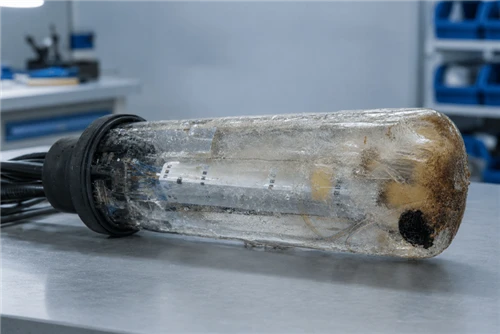
| Water or dust ingress after installation | Missing sealing cap, half-mated drop connector, damaged gasket, or IP rating below the site exposure. | Audit every unused port cap, verify full latch engagement, and record IP rating by site type during acceptance. |
| Unexpected high loss on a PON branch | Integrated splitter ratio too high, connector contamination, extra adaptor pair, or unplanned splice. | Total splitter loss, fiber attenuation, connector loss, splice loss, and margin before approving a 1:16 or higher-density MST. |
| Terminal swap required after take-rate growth | Port count sized to day-one subscribers instead of homes passed and lifetime take rate. | Use homes passed × expected take rate + spare ports, then round up to a standard port count. |
| Macrobend or fatigue near the terminal | Poor slack storage, short feeder stub, tight routing, or cable flapping on aerial spans. | Specify stub length from the field route, keep bend radius within cable datasheet limits, and plan slack storage before installation. |
| Port records do not match subscribers | No port map, inconsistent labeling, or undocumented reconnects during churn. | Use a port-to-subscriber log, label both MST port and drop cable, and photograph the final port state at handover. |
11. Frequently Asked Questions
-
Q: What is an MST (multiport service terminal) in fiber?
A: An MST is a sealed, pre-connectorized fiber distribution terminal used in the FTTH access network. It presents several weatherproof output ports built on hardened connectors, so a technician can plug in a subscriber drop without fusion splicing and without opening the enclosure. Most MSTs are fed by a single stub or feeder cable, and many house an internal optical splitter - which is why they are also sold as multiport splitter terminals.
Q: What does MST stand for in fiber optics?
A: MST stands for multiport service terminal. The term describes a hardened, environmentally sealed terminal in the optical distribution network that breaks a feeder or splitter output into multiple plug-and-play drop ports. You will also see the names multiport drop terminal, multiport tap, and FTTH access terminal used for the same device class.
Q: When should I use an MST instead of a splice closure or fiber distribution box?
A: Use an MST where you want fast, less-specialized subscriber connection: its hardened ports let a technician add a drop in minutes with no splicing and no enclosure opening, which lowers truck-roll time and mean time to repair. Use a splice closure where you are joining feeder or distribution fibers mid-span and connection speed is not the priority. Use a fiber distribution box or access terminal when you need adapter-based patching, pigtail splicing, or splitter housing inside an openable box and are willing to trade plug-and-play speed for lower per-port hardware cost.
Q: How many ports should an MST have: 4, 6, 8, 12 or 16?
A: Size the port count to the homes the location must serve over the terminal's life, not just on day one. Take the homes passed within the drop radius, apply your expected take rate, then add spare ports for growth. As a rule of thumb, 4 and 6 ports suit sparse rural and low-density aerial runs, 8 ports is the common suburban default, and 12 and 16 ports fit dense multi-dwelling units and urban clusters. If the terminal carries an integrated splitter, the port count usually mirrors the split ratio (a 1:8 splitter feeds 8 ports).
Q: What connector do MST terminals use?
A: MST output ports use hardened (ruggedized) connectors rated for outdoor mating, most commonly an OptiTap-style hardened SC/APC interface, with hardened MPO used for multi-fiber drops. The single rule that matters is ecosystem match: the terminal port, the pre-connectorized drop cable, and any field-installed plug must all share the same hardened format. Mixing incompatible hardened systems is the most common cause of a drop that will not seat or seal.
Q: What IP rating does an MST need?
A: Match the IP rating (IEC 60529) to the mounting environment. IP65 - dust-tight with protection against water jets - is generally adequate for sheltered aerial and pole mounting. IP67, which adds temporary immersion to about 1 m, suits exposed aerial and pedestal use. IP68, rated for continuous immersion to a manufacturer-stated depth, is the choice for buried handholes, flood-prone vaults, and below-grade applications. Unused ports must keep their sealing caps fitted, or the rating no longer holds.
Q: Does an MST include an optical splitter?
A: It can. A multiport splitter terminal houses a PLC splitter inside the sealed body, so one feeder fiber is split internally and presented as multiple drop ports. A non-split MST instead breaks out individually pre-terminated fibers from a multi-fiber stub. Choose the integrated-splitter version when you want the split point close to subscribers; choose the breakout version when splitting happens upstream at a cabinet or distribution point.
Q: Can you add ports to an MST after installation?
A: Generally no - an MST's port count is fixed by its sealed body and internal configuration, so you cannot field-add ports the way you might in an openable distribution box. That is exactly why port sizing matters: under-porting forces a full terminal swap and a second truck roll when take rate grows. Specify spare ports up front, or plan terminal placement so an additional unit can be added on the same span.
Recommended MST Configuration by Deployment Scenario
Instead of treating products as a separate sales block, match each configuration to a deployment scenario. The goal is to help the buyer turn the checklist above into a clean BOM line: port count, connector ecosystem, splitter choice, IP rating, stub length, mounting kit, and test documentation.
MST Box (Multiport Service Terminal)
Best fit for general FTTH drop distribution where the design needs 4, 8, 12, or 16 hardened output ports. Use it when the split point may be upstream or inside the terminal, and request the exact port map and IL/RL report for the selected build.
View MST boxOptiTap-Compatible Fiber Access Terminal
Best fit when the existing drop-cable inventory is built around an OptiTap-style hardened SC/APC interface. Confirm shell geometry, key orientation, APC polish, and sealing-cap compatibility before mixing suppliers.
View access terminalMultiport Splitter Terminal
Best fit for distributed-split ODN designs where the split point should sit close to subscribers. Check the full PON loss budget before choosing 1:16, and request splitter loss, uniformity, and port map documentation.
View splitter terminalPLC Fiber Optic Splitters
Best fit when splitting remains upstream at a cabinet, FDH, or distribution point. Pair with a non-split breakout MST when the network needs centralized split management and cleaner optical-budget control.
View PLC splittersNeed a specific port count, a particular hardened connector ecosystem, a custom stub length, or private-label FTTH drop kits with per-batch test certificates? Glory Optical's OEM/ODM program covers custom terminal configurations, branded packaging, and factory test documentation. Learn about OEM / ODM →
Article by the Glory Optical engineering team. Ningbo Glory Optical Communication Co., Ltd. is a fiber optic component manufacturer and ODN solution provider serving telecom operators, data centres, and ISPs in 50+ countries. Configuration options, IP ratings, and splitter loss figures in this guide reflect published IEC, ITU-T, and Telcordia frameworks; confirm the exact specification of any unit against its current datasheet before design or procurement.
Request a quote · Contact the technical team · OEM / ODM services · About Glory Optical
Standards referenced: IEC 60529 (ingress protection / IP rating); IEC 61753-1 (passive component performance framework); IEC 61300-3-35 (connector end-face inspection); ITU-T G.671 (optical components); ITU-T G.984.2 / G.9807.1 / G.989.2 (GPON / XGS-PON / NG-PON2); Telcordia GR-3120 and GR-771. Always verify against current product datasheets before design or procurement.