
An underground FTTH access design can deliver a connection without a separate boundary box at every property. The design must still provide an assigned optical connection, a usable route to the premises, and suitable protection and maintenance access. Choose chamber terminals and boundary boxes by their function in that route, then decide which civil works must precede customer orders and which can follow them.
A familiar question illustrates the problem: why does an address show FTTP availability when no Toby box is visible? A thinkbroadband discussion from August 2024 raised exactly that concern, and the replies show how much practice varies between areas. Confirm the applicable policy with the operator for the area concerned.
For engineers and procurement teams, the practical task is to distinguish service availability from a completed drop route. A network may support an order while the final survey, duct work, cable installation and activation remain outstanding.
Key takeaways
- Function, not name. An access chamber provides underground space, a terminal provides the optical connection, and a boundary box marks an access or handover position. Confirm what is actually installed inside.
- A separate boundary box is a design choice. The handover function can be performed at the boundary or at the building entry point. Decide which, and record the answer before the first duct is laid.
- Availability is not completion. An orderable address can still be waiting on survey, duct work, cable installation and activation.
- A port count includes the input. A 1:8 splitter terminal has eight outputs plus an input, so check whether the input is connectorised or stubbed.
- Sealing and re-entry are separate qualifications. A Category S closure standard frames the requirement, while certification belongs to the individual product; treat re-entry as a tested property.
- Working space is part of the design. A terminal that fits inside a chamber can still be difficult to connect, clean or maintain.
- Close the records and the ownership. Note what is complete, what remains, and who owns each outstanding item.
1. What does each underground node actually do?
An access chamber provides serviceable underground space, while a fiber terminal provides the optical connection or distribution function. A boundary box marks a local access or handoff position; its contents determine whether it also performs an optical function. These roles can be combined, so confirm the configuration against the supplier's drawing.
| Component | Main role | What the name leaves unproven |
|---|---|---|
| Access chamber or handhole | Access to ducts, cables, slack and installed equipment | That the chamber itself seals the optical connections against water; a cover loading rating is a separate property |
| Chamber-mounted terminal | Provides assigned drop connections, with splitting only where specified | That every connection is a subscriber output, or that hardened plugs are interchangeable between models |
| Splice closure | Protects fiber joints and manages fibers and cable entries | That it presents externally accessible subscriber ports |
| Boundary box (also called a Toby box or boundary access point) | Provides a small access or handover position near a property boundary | That a splitter, connector or live fiber is installed inside |
| Building entry or demarcation enclosure | Provides the specified transition, demarcation and service boundary at the premises | That it replaces the upstream distribution terminal |
The distinction appears in manufacturer documentation. Radius CTS describes its Toby Box² as primarily housing microducts, with provision for a splice enclosure. "Toby box" is a regional term that several suppliers apply to comparable boundary boxes: Emtelle markets the Toby Box+ as an underground storage position at the boundary to the customer. Separately, HellermannTyton's Customer Connection Point is an optical termination, demarcation and test point that can be housed in a small underground chamber or mounted on a façade. These are comparable products from different suppliers, so compare the function and the drawings for each candidate.

Figure 1 - One product, four names. This terminal is marketed as a FAT, CTO, NAP or pre-connectorized terminal depending on which vocabulary the operator uses, and the same page lists 16 drop outputs, an optional 1 : 16 splitter and wall, pole and messenger mounting (messenger lashing uses an optional bracket). The label therefore describes a market convention, not a configuration. Request the drawing. Candidate to evaluate: GL-CTO16 FAT fiber access terminal.
Two conceptual routes follow from that split:
- With boundary access: distribution fiber → chamber terminal → duct/drop route → boundary access box → building entry → ONT.
- Without a separate boundary box: distribution fiber → chamber terminal → approved duct/drop route → building entry → ONT.
These are functional diagrams, not construction drawings. A boundary box can perform a purely mechanical handover function, and a continuous cable can pass through several duct sections with joints between them. Network-side documentation often refers to the CBT in the serving chamber or jointing box; those are network-side components, separate from the property-side parts described here.
Is a separate boundary box actually required?
The two routes differ in where the handover function is performed, and that is the decision worth making explicitly. In some designs the function is performed at the property: the building entry or demarcation enclosure provides the termination, the demarcation and the test point. In others the route needs its own access position at the boundary. Four questions usually settle it.
| Question | If the answer is yes | If the answer is no |
|---|---|---|
| Does the design need a test and demarcation point outside the premises? | Provide it at a boundary box, or at a building entry point that performs that role | The building entry point may already cover it |
| Will later addresses be connected by intercepting and teeing into this route? | Reserve a boundary access position and document how the next connection is made | Route capacity and spare fibers matter more than an access position |
| Does the applicable operator or project specification require a boundary access position? | Follow the specification; it governs the design | Decide on route and maintenance grounds |
| Can the building entry accept the drop with the required sealing and ventilation? | Treat the entry as its own design check, as set out in Section 6 | Introduce a break or a handover point upstream of the entry |
The answer changes with the operator, the property type and the route, so confirm it for the specific project. In the UK this access position is often called a Toby box. Record the decision before the first duct is laid.
For the civil access component, Glory Optical's GL58 fiber optic handhole is a candidate to evaluate against the approved chamber and cover drawings. Select the internal terminal and its mounting arrangement separately.

Figure 2 - The civil access component. A chamber is selected on usable internal space, duct entries, cover loading class and maintenance access. The supplier of this model publishes a cover load rating of 11 tons and cites ANSI/SCTE 77 structural load tests; a published figure is a starting point, so confirm the declared class and its test evidence against the load the location actually imposes. Candidate to evaluate: GL-FMH-A underground fiber optic junction box.
2. Prebuild to the boundary, or construct the drop after an order?
Underground FTTH access design usually turns on when the civil work happens. Prebuilding brings more work forward; construction after an order defers part of the route until demand is confirmed. Neither approach removes the need for route approval, usable optical capacity and installation access. Compare the complete delivery sequence, including the civil work around any boundary box.
| Decision factor | Prebuild to the boundary | Construct the remaining route after an order | Engineering or procurement implication |
|---|---|---|---|
| Civil-work timing | More work is completed during the initial build | More work remains for the customer connection stage | Include mobilisation, permits and reinstatement in both options |
| Uncertain take-up | Infrastructure may be installed at premises that do not order | Some expenditure can follow confirmed demand | Model local take-up and delivery costs; do not assume universal savings |
| Street access | Can suit a coordinated build or a limited access window | May require later visits as orders arrive | Check restrictions on reopening the route |
| Activation readiness | The remaining route may be shorter, but still needs validation | Survey or duct construction can affect the connection date | Record exactly what is complete and what remains |
| Expansion | Boundary access points can support planned later work | Later connections need a workable route and capacity plan | Reserve space and document how the next subscriber will connect |
Three factors usually dominate the choice, and they pull in different directions. Where civil access windows are tight and one visit costs less than several, prebuilding the route and any Toby box in a single campaign avoids reopening the surface. Where take-up is genuinely uncertain and later access remains practical, deferring the remaining route lets expenditure follow confirmed demand. Where the route will serve later addresses, weigh the cost of returning against the cost of work that may never be used.
Decision rule: favour prebuild where coordinated civil access and predictable connections justify the initial work. Consider staged construction where demand is uncertain and later access is practical. In either case, approve the route and the responsibilities before promising a connection date.
Confirm the delivery sequence in use for the project. Openreach's installation guidance describes surveys where they are needed and notes that blocked ducts can extend an installation, so an address can be orderable while physical work is still outstanding.
3. Specify useful capacity, not just a number on the box
Fiber capacity, cable-entry count, optical input count and subscriber output count describe different constraints. A node is usable only when all of them match the intended connections. Procurement should request a port map and splice schedule alongside the headline capacity.
A port count is a count of connector positions, not of services. For a non-stubbed 1:8 splitter terminal those positions are the eight outputs plus the input, so the assembly is specified with nine connections. Corning's SRP 004-802-NAFTA documents that arrangement for a non-stubbed terminal. Other terminals count differently, so check the drawing for the model being ordered.
Glory Optical's GL-H03 splice closure specifications show a different capacity question, because splice capacity and cable entries are separate fields:
| Published metric | Value | Scope and procurement meaning | Source date |
|---|---|---|---|
| Fiber capacity | 48 fibers | GL-H03 splice accommodation; not 48 subscriber connector ports | Product page checked 23 September 2026 |
| Cable entries | 2 | Must match the cable route; fiber capacity does not create additional entries | Same product page |
| Cable outside diameter | 7–14 mm | Published entry range; compare with the actual cable and sealing configuration | Same product page |

Figure 3 - Four different numbers on one box. The published specification for this distribution box lists 16 drop ports, up to 16 SC simplex adapters, an eight-way cable-entry set and 48 cores of splice capacity. Each answers a different question, so a headline figure is only meaningful once you know which question it answers. Candidate to evaluate: GL-OTB-P027 FTTH fiber distribution box.

Figure 4 - Count the positions, including the input. The eight adapters are the outputs; the input is brought out separately. Whether that input is a connector or a pigtail is what decides the connector count on the drawing. Candidate to evaluate: 1×8 LGX cassette fiber optic splitter.
Obtain the approved drawing and configuration before ordering, and record the feeder connection, subscriber outputs, spare capacity, splitter arrangement and upstream allocation for every candidate terminal. A spare socket is useful only if the optical path behind it can support the intended service. Where the design introduces another splitter, reassess the complete optical budget, because the extra splitter changes loss as well as port count; Glory Optical's GPON loss budget and splitter ratio guide covers that side of the check. The component characteristics behind those allowances are set out in ITU-T G.671, and the physical-layer limits for the PON in ITU-T G.984.2.
4. Qualify the installed underground assembly
Underground suitability belongs to the complete installed configuration: housing, seals, cables, connectors, unused-port closures and mounting. A headline IP rating is defined by IEC 60529 and applies to the enclosure as tested, so request evidence that matches the complete assembly and the specific water exposure and maintenance procedure being specified.
IEC 61753-111-09:2021 contains the minimum tests, severities and measurement requirements for a sealed fiber-optic closure to be categorised for Category S, the subterranean environment. Certification belongs to the individual product, and to the environment it was tested for; a chamber or terminal design calls for its own assessment. For a closure procurement it frames the qualification discussion, which is the useful part. The optical joint itself is covered separately: ITU-T L.12 covers optical fibre splices, and the supplier should confirm the splice protector and tray capacity the design needs.
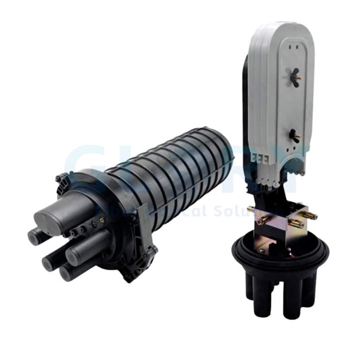
Figure 5 - A published rating is the starting point, not the finish. The manufacturer-published figures for this closure are an IP68 rating, up to 96 cores of splice capacity (4 × 24 trays) and suitability for direct burial. What Section 4 asks for is the evidence behind that rating for the exact cable, seals and re-entry procedure in your design. Candidate to evaluate: dome closure fiber optic, model GL5-RS-AM3.
Ask the supplier to identify the tested model, cable sizes, entry seals, connector condition, test method, exposure conditions and acceptance criteria. Where immersion performance matters, obtain the actual test conditions behind the rating, covering depth, duration and the maintenance cycle.
Maintenance needs its own evidence. IEC 61300-2-33:2026 evaluates a protective housing or a hardened connector after a specified number of assembly and disassembly operations, and its scope covers sealing performance after repeated opening and closing, and after repeated mating and demating. Specify the relevant procedure and severity for the product being ordered, and treat re-entry as a tested property with its own evidence.
Selection rule: if a future customer connection requires opening the enclosure, include the opening, resealing and existing-fiber protection procedure in qualification. If it uses an external hardened port, qualify the exact mating connector, cap and handling procedure instead.
The chamber cover has a separate structural job. Match its loading requirement to its installation location and the project specification; the ingress rating of the closure selected in Section 3 covers water exposure, so check traffic loading on the cover separately.
5. Check working space and the complete drop route
A terminal that fits inside a chamber may still be difficult to connect, clean or maintain. Check the working space with the actual cables and hardware, including connector removal, lid movement and supported service slack. Measure the usable opening and the internal obstructions, and treat the external dimensions of the box as a separate figure.
Use the layout review to confirm:
- The terminal can be supported and reached without pulling on live cables.
- Connectors can be uncapped, inspected, cleaned and mated using the specified tools.
- Cable bends meet the complete cable manufacturer's installation and operating limits.
- Duct entries, brackets and slack storage leave the maintenance path clear.
- Future drop installation can leave unrelated live fibers undisturbed.
Bend performance depends on the fibre as well as the cable construction. ITU-T G.657 defines the bending-loss-insensitive single-mode fibre categories used in many drop cables, and the calculated minimum bend radius for the installed cable still governs the design.
Contamination makes this more than a dimensional check. Corning's SRP 004-171 instructs technicians to clean a muddy terminal exterior before removing its protective plugs. Plan a clean handling position and adequate supported cable movement. Follow the cleaning procedure published for the selected product.
For the drop, confirm the route, duct condition, bends, cable construction and installation method together. A preconnectorized assembly also needs enough passage for its protected connector and pulling arrangement, because the cable diameter covers only part of the route. Glory Optical's FTTH drop cable selection guide takes the comparison further for indoor, aerial and duct applications; the selected cable must also match the terminal entry and seal. Cables intended for duct and tunnel routes carry their own requirements, addressed for example in ITU-T L.100.
6. Building entry is a separate design check
Keep the building transition explicit on the drawing, and treat it as its own design step with its own sealing and ventilation requirements.
Openreach's March 2026 New Sites Fibre Handbook, page 7, states that a duct must not be routed directly from an underground Openreach jointing chamber into a building, because it presents a risk of gas ingress from the underground network into the property. That is a specific operator safety requirement, and it is the reason the route usually needs a break, a seal or a ventilation arrangement at the entry. Other operators and countries set their own entry rules, so apply the ones that govern the project.

Figure 6 - The in-premises end of the same route. The published figures are a fibre bend radius of ≥40 mm and a drop-cable range of Ø2–4 mm or 2×3 mm. Those two numbers are what the selected cable has to fit before the entry detail is frozen, and routing the drop through the outlet is a design step, not a finishing item. Candidate to evaluate: GL-GPMB-E3 fibre optic outlet.
7. Put the decisions into an RFQ
A useful underground FTTH request for quotation defines how the node will be used and serviced. Send the route drawing, connection map and environmental conditions with the component list, so that suppliers can identify configuration gaps before a sample or production order is approved.
| RFQ field | Information to provide or request |
|---|---|
| Network role | Distribution terminal, splice node, boundary access point or building transition |
| Build sequence | What is installed initially and what is added per customer order |
| Boundary access | Whether a boundary box (Toby box) is required at all, and what function it performs |
| Capacity | Feeder fibers, optical inputs, subscriber outputs, splice schedule and planned reserves |
| Optical arrangement | Splitter location and ratio, fiber assignment and project loss limits |
| Mating interfaces | Exact plug and receptacle part numbers, polish, caps and compatibility evidence |
| Cable entries | Cable dimensions and profile, strength members, sealing parts and retention method |
| Chamber layout | Usable opening, internal space, ducts, bracket positions and working clearances |
| Environment | Expected water exposure, temperature, contaminants and cover loading requirement |
| Maintenance | Re-entry method, replacement seals, tools and protection of live fibers |
| Documentation | Revision-controlled drawings, component list, installation instructions and applicable test reports |
Avoid an RFQ that asks only for "an underground box with enough ports." It leaves unresolved whether the supplier is quoting a civil chamber, a splice closure or a loaded subscriber terminal.
| Route position | What the specification has to fix | Candidate in this guide |
|---|---|---|
| Distribution terminal at or near the boundary | Port map, input arrangement, splitter position, sealing and re-entry | Figure 1 |
| Civil access chamber | Usable internal space, duct entries, cover loading class, maintenance access | Figure 2 |
| Distribution box feeding several drops | Drop-port count, adapter count, cable entries and splice capacity kept separate | Figure 3 |
| Splitter position | Ratio, connector count including the input, cassette or tube format | Figure 4 |
| Splice or joint position | Splice capacity, cable-entry count, re-entry method, ingress evidence | Figure 5 |
| In-premises termination | Drop-cable range, bend radius, adapter type, mounting | Figure 6 |
The figures show candidates from the Glory Optical range so that a specification can be discussed against a concrete assembly. They are selection candidates for evaluation against the approved design, not statements that a given model suits every route, loading or groundwater condition. Confirm the drawing, the configuration and the test evidence for the project before ordering.
8. Verify the node before accepting the build
Acceptance should connect the approved design to the installed hardware and the test records. Treat civil readiness, mechanical fit and optical performance as separate checks, then confirm the end-to-end service when activation is in scope. Record the maintainability of the node as well, thinking ahead to the next connection. Use this engineering review, adapted to the operator's acceptance requirements:
- Trace the route. Match the serving node, assigned optical output, drop path, boundary access where present and building entry to the drawing. Record unfinished civil work and its owner.
- Match the configuration. Compare delivered labels, connector parts, cable sizes, seals and brackets with the approved bill of materials. Resolve substitutions before installation.
- Demonstrate service access. On the approved sample or a controlled installation, confirm connector access, cable support, slack handling and the specified resealing procedure without disturbing adjacent circuits.
- Verify optical performance. Use the operator's test method, wavelengths and acceptance limits. Link each result to its fiber or port, and complete registration and service checks when required.
- Close the records. Retain node and port IDs, route changes, configuration revisions, photographs, test results and responsibility for outstanding work.
Where the connection depends on works by another party, confirm in writing which party owns each outstanding item and how any additional construction charge is authorised before a customer connection date is promised.
Settle the underground FTTH access design before selecting the individual boxes. Once the route, node functions and construction stages are clear, send Glory Optical the project drawings and RFQ requirements for component and configuration review. Include the maintenance arrangement so the proposed assembly can be evaluated for the next connection as well as the first.