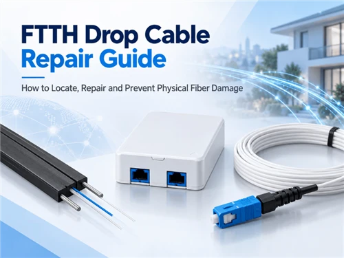
Choose an FTTH drop cable by mapping the route, selecting a construction rated for that environment, and matching it to the entry seal, clamp and connector. For a protected indoor run, prioritize building-use requirements and bend control. For an aerial drop, establish the support and span design; for a duct route, check the installation method, moisture exposure and available clearance.
An FTTH (fiber-to-the-home) drop connects the distribution point to the subscriber premises. This guide helps ISP engineers, contractors and procurement teams move from a route sketch to a cable specification, a compatible assembly and a comparable quotation.
1. Indoor, aerial or duct: select the drop cable by route
Start at the distribution terminal and trace the cable to the subscriber outlet. Mark every change in exposure or installation method, especially the building entry: this is where an outdoor route meets indoor fire-performance and cable-management requirements.
Use the route sketch to complete this screening table:
| Route section | Cable characteristics to request | What must be checked before approval |
|---|---|---|
| Protected indoor wall, corridor or riser | Construction suitable for the installation space, with the required fire performance | Building requirements, support method, bend limits and outlet routing |
| Outdoor wall or façade | Documented weather resistance for the expected exposure | Sunlight, moisture, temperature and fixing method |
| Suspended pole-to-premises span | A cable and support arrangement designed for the proposed aerial installation | Span, sag, wind/ice design conditions, attachment hardware and entry angle |
| Underground duct | Cable approved for the duct environment and proposed installation method | Water exposure, route bends, pulling limits and end sealing |
| Microduct with blowing or pushing | Cable approved for the specific duct and installation equipment | Cable/duct dimensions, equipment compatibility and installation instructions |
| Direct burial | An explicitly suitable buried construction | Ground conditions, mechanical protection, water resistance and locating provisions |
Flat and dielectric constructions are available for several installation environments. Corning's drop cable portfolio, for example, lists aerial, direct-buried and indoor/outdoor designs. Use the stated application of the exact product when selecting among these options.
Mixed outdoor-to-indoor routes
A continuous indoor-outdoor cable can simplify the building entry when its documented ratings satisfy both environments and the building's installation requirements. A protected transition to a separate indoor cable gives the designer another option. IEC 60794-6:2020 covers indoor-outdoor optical cables, including outdoor designs with indoor fire performance and indoor designs with added weather resistance.
Use Glory Optical's FTTH cable range to shortlist candidate constructions. Record the chosen configuration and datasheet revision alongside the route drawing so procurement and installation teams work from the same specification.

Recommended: Drop Core Fiber Optic
A practical candidate for outdoor-to-building FTTH drops when the project needs a flat, dielectric, gel-free cable structure. Match the final configuration to the route, terminal entry and sealing hardware before ordering.
Published configuration: 4.5 × 7.0 mm · 1–2 fibers · G.652D / G.657A options · pre-connectorized assemblies available.
View product2. GJXFH, GJXH and GJYXCH: check the complete construction
Order model-coded drop cables against a dimensioned cross-section. For GJXFH, GJXH, GJYXCH and related constructions, the drawing should identify the fiber unit and every reinforcing or conductive element so the buyer can assess both mechanical support and any all-dielectric requirement.
The distinction matters because different elements perform different jobs:
| Element | Function to establish in the drawing | Procurement question |
|---|---|---|
| Internal strength member | Reinforces the optical cable unit | Is it steel, fiber-reinforced plastic (FRP), aramid or another specified material? |
| Messenger or self-supporting element | Carries the designed aerial load | What material, attachment method and installation limits apply? |
| Tracer or locating conductor | Provides a conductive path for compatible locating equipment | Is it intended only for locating, and how is it accessed and terminated? |
An all-dielectric requirement applies to the complete cable, including its support and locating elements. YOFC's GJYXFCH construction sheet makes the distinction visible: it identifies a stranded-steel self-supporting member, alongside the separate internal strength-member description. A buyer evaluating that construction would record the steel messenger explicitly.
Put the all-dielectric requirement on the purchase order where the project calls for it. Specify the locating method separately, including the role and termination of any tracer conductor. Keep material substitutions under the same drawing-approval process as dimensional changes.
The next step is to match the chosen cross-section to its accessories. Section 5 works through that check using dimensions published in Glory Optical's product catalog.
3. G.657.A1 vs A2 and the finished cable's bend radius
Select the fiber category for the optical design and use the finished cable's bend-radius and pulling limits during installation. These two specification levels tell the designer how the fiber behaves and the installer how to handle the assembled cable.
ITU-T G.657 defines bending-loss-insensitive single-mode fiber and cable characteristics. Category A fibers comply with G.652.D; A1 and A2 differ in macrobending performance. Choose A2 where the optical design needs its tighter-bend performance, then obtain the limits for the actual cable construction.
Request separate values for installation and installed bend limits, pulling load and the conditions under which those limits apply. For a flat or composite cable, ask the supplier to identify the applicable bending direction and which part of the construction a quoted radius describes. Follow the manufacturer's instructions, as emphasized in the FOA cable installation guide.
For an XGS-PON upgrade, review the optical distribution network's losses and operating requirements as well as its bend conditions. The ITU's G.9807.1 technical overview specifies a basic downstream band of 1575–1580 nm and upstream band of 1260–1280 nm. Keep these service wavelengths distinct from a 1625 nm bending-test wavelength when comparing reports; the upgrade decision needs a network assessment, not an automatic A1-to-A2 replacement rule.
4. LSZH, weather resistance and fire-test evidence
Specify environmental exposure and fire performance in separate fields. An LSZH (low smoke zero halogen) jacket description should be supported by the relevant test reports and the classification required for the installation space.
For outdoor sections, review sunlight, moisture and temperature performance. For indoor sections, have the project designer identify the applicable building-use requirements, then match those requirements to the ordered cable's documentation.
When reviewing fire-related evidence, distinguish what each report actually measures:
| Evidence | What it addresses | Procurement follow-up |
|---|---|---|
| IEC 61034-2 | Smoke density from cables burning under defined conditions | Identify the tested cable and the required smoke-performance result |
| IEC 60754-2 | Acidity and conductivity associated with combustion gases from cable materials | Match the tested materials and acceptance criteria to the proposed construction |
| IEC 60332-1-2:2025 | Vertical flame propagation for a single cable under the specified test | For grouped installation, identify the additional applicable fire requirements |
Record the standard edition, test object, acceptance criteria and report scope. The single-cable test in IEC 60332-1-2 does not establish grouped-cable fire performance; the installation specification must address that condition separately.
5. Match the drop cable to its terminal, seals and clamps
Review the drop cable and its terminal hardware as one assembly. The approval should identify the cable profile, the exact entry seal, the retaining hardware and the termination kit, making any replacement straightforward to compare.
Use the following interface review as a procurement worksheet:
| Interface | Compare on the drawings | Evidence for approval |
|---|---|---|
| Cable to entry seal | Round diameter or flat width/thickness, tolerances, seal insert and allowed cable count | Identified port/insert combination covering the proposed cable |
| Cable to clamp | Cable profile, supported element, clamp part number and installation method | Manufacturer-approved retention arrangement |
| Cable to connector | Jacket and buffer dimensions, preparation length and strain relief | Termination-kit instructions covering that cable format |
| Connector to terminal port | Optical interface, polish, keying, coupling and environmental housing | Matching interface documentation and sample connection |
| Prepared cable to internal routing | Protected fiber path, splice protection and space for service slack | Completed sample with supported fiber routing and normal enclosure closure |
A dimension check using Glory Optical's catalog
The B04 gel-sealing distribution box lists 2 × 3 mm flat cable among its drop-output options. Glory Optical's gel-free flat drop cable product lists a 4.5 × 7.0 mm outer profile. Comparing these published dimensions immediately identifies a question for procurement: which output and seal, if any, are approved for the larger cable?
The B04 page also lists feeder-entry configurations separately. Ask Glory Optical to confirm the intended port and accessory drawing before putting the two items on the same assembly BOM. This is a catalog-based comparison, not a claim that the pair has been tested or that a field failure occurred.

Recommended: B04 Gel Sealing Fiber Optic Distribution Box
This compact access box is useful where the drop cable, seal and terminal need to be evaluated as one assembly. Its published drop-output sizes make it especially relevant to the interface check in this section.
Published configuration: IP67 · 10-core splicing · 4 drop outputs · wall / pole / strand mounting.
View productFor sample approval, have the assembler prepare the cable, install the specified seal and retention parts, route the fiber and close the box. Record the part numbers and photographs. A gap around the entry, cable movement in the retention point or a fiber trapped by the lid is a reason to correct the assembly before bulk ordering. Complete the project's environmental qualification separately.
6. Pre-terminated drop cable or field termination?
Choose the termination method together with the route and the operator's maintenance plan. Factory termination, fusion-spliced pigtails and field-installable connectors create different requirements for installation access, component matching and repair.
| Delivery or termination method | Useful when… | Confirm before ordering |
|---|---|---|
| Factory-terminated drop | The mating interfaces and required lengths are known | Complete pulling-head dimensions, protected connector clearance, end identification and slack storage |
| Bulk cable with fusion-spliced pigtail | Field length adjustment and a protected splice location are available | Splicing access, pigtail specification, sleeve/tray fit and test requirements |
| Field-installable connector | The operator permits the method and installers have the appropriate kit | Exact cable/buffer compatibility, preparation tools, instructions and acceptance criteria |
The protected connector and pulling attachment often determine whether a pre-terminated assembly can pass through the route. Ask for their complete dimensions and the approved pulling method early, while the duct and termination plan can still be adjusted.
Illustrative clearance check: suppose a route has a verified 16 mm clear bore and the proposed rigid protective head is 18 mm in diameter. The completed assembly cannot pass through that bore, even if the cable itself is only 3 mm wide. The choices are a larger verified pathway, a manufacturer-approved smaller pulling head, or field termination after the cable is installed. These dimensions are example inputs, not specifications for a Glory Optical product.
Glory Optical's ROC drop cable listing includes pre-connectorized options. Provide the terminal interface, route clearance and required length when asking which assembly configuration is available.

Recommended: ROC Drop Cable
Suitable to review when field preparation speed, tracing or factory-terminated drop assemblies are part of the deployment plan. Confirm the connector format, finished assembly dimensions and route clearance before selecting a pre-terminated option.
Published configuration: ROC toneable 3.0 × 6.0 mm · G.657A1 / A2 · pre-connectorized assemblies available.
View productAt each optical mating point, match the connector format and polish. APC (angled physical contact) and UPC (ultra physical contact) end faces must not be mated directly; the FOA's connector guidance explains this incompatibility. For an outdoor terminal, also record the coupling, keying and sealing system on the assembly drawing.
7. Compare FTTH drop cable cost and build the RFQ
Compare quotations for the same installed connection: cable, termination, compatible accessories, installation work and acceptance testing. Then send every supplier a controlled specification and require a line-by-line response to deviations.
Compare material savings with installation work
Illustrative cost calculation-not a market quotation or a Glory Optical result: assume 100 drops at 50 m each. A cable price reduction of $0.02/m saves $100 across 5,000 m. If its preparation method adds four minutes per drop, the additional work totals 400 minutes; at an assumed labor rate of $30/hour, that costs $200. Under those assumptions, the lower cable price raises cable-plus-labor cost by $100, before accessories, transport or revisits.
Replace those inputs with your quoted prices and measured trial-installation times. Compare equivalent fiber counts, environmental ratings and termination formats before evaluating the price difference.
Specify supply conditions by configuration
Ask whether MOQ applies to the entire order or separately to each fiber count, color, printed marking and cut length. For scheduling, distinguish sample approval, production readiness and shipment timing, and identify which event starts the quoted lead time. This makes a staged delivery plan easier to evaluate against the installation schedule.
Use this checklist for each distinct drop construction:
| RFQ field | Information to provide or request |
|---|---|
| Application | Destination country, operator requirements and a route sketch identifying each environment |
| Optical design | Fiber category, active and spare fiber count, identification scheme and required optical limits |
| Construction | Dimensioned cross-section, tolerances, reinforcement, messenger and tracer details |
| Installation | Aerial design conditions or duct method; required pulling, bending and support information |
| Jacket and environment | Material, exposure requirements, temperatures and applicable fire-performance evidence |
| Interfaces | Terminal model, exact entry/output position, seal/insert, clamp and connector part numbers |
| Delivery format | Bulk reel or cut/terminated lengths, length tolerances, end protection and packing |
| Identification | Cable marking, length marks, reel/assembly IDs and batch traceability |
| Acceptance | Sample assembly review, optical tests, document requirements and agreed inspection plan |
| Commercial terms | Quantity by configuration, MOQ, sample availability, production schedule, shipment plan and quotation validity |
| Change control | Drawing revision and written approval before any material, geometry or interface substitution |
For a Glory Optical inquiry, send the route sketch and terminal drawing with this checklist. The published OEM and ODM service covers discussions of cable configurations, drawings, marking and packaging. Request a written proposal identifying the offered configuration, deviations, documents and delivery terms so your team can approve the actual order.
8. Drop cable acceptance: inspection, insertion loss and OTDR
Define how the cable, its terminations and the installed link will be accepted before placing the order. A reel report, a connectorized-assembly report and a completed subscriber-link test answer different questions and should remain identifiable in the handover records.
Use three review stages:
- Before shipment: approve the drawing revision and sample fit; agree on the relevant qualification documents, routine optical records, identification and inspection scope.
- On receipt: reconcile cable and assembly IDs with the order; check reel/end protection and visible damage; complete the agreed incoming checks before committing material to installation.
- After installation: inspect the completed routing, fixation, seals and terminations; test the defined link; save results against the subscriber port and cable identification.
For optical acceptance, define the test boundary, wavelengths, reference method and allowable loss. A source and power meter or optical loss test set measures insertion loss, which should be assessed against the agreed link budget. The FOA's installed-cable testing guidance explains why the reference method and compatible test cords matter.
An optical time-domain reflectometer (OTDR) helps characterize events and locate faults. Select an instrument and settings suitable for the short link, with appropriate launch and receive fibers where end-connection measurements are required. The FOA OTDR testing guide explains the resolution and setup considerations. Save the traces with the test settings and link identification so another technician can interpret the result later.
For the wider installation sequence and handover context, see Glory Optical's FTTH installation and testing checklist.
Frequently asked questions
These questions address two final configuration choices: spare capacity in the drop and connections between equipment with different polish types. Both should be resolved before the assembly is ordered.
How many fibers should a residential FTTH drop contain?
Choose the fiber count from the operator's service plan. A single-fiber PON connection can use one active fiber; a second or additional fiber may be specified for spare capacity or planned services. For a multi-unit property, establish the subscriber layout and required capacity, then include identification and storage provisions for the unused fibers.
Can a patch cord have APC at one end and UPC at the other?
Yes. A hybrid patch cord can connect an APC interface at one end of the route to a UPC interface at the other, provided each end mates with the matching polish and connector format. The two different polishes are on opposite ends of the cable; they are never mated directly to each other.
The FOA's hybrid-patch-cord example describes this arrangement for an APC patch panel and UPC equipment interface.
Preparing a project order? Send Glory Optical your drop-cable RFQ with the route sketch, fiber count, terminal and connector details, quantity and destination. Request a cable drawing, accessory list and agreed acceptance documents for the proposed subscriber connection.