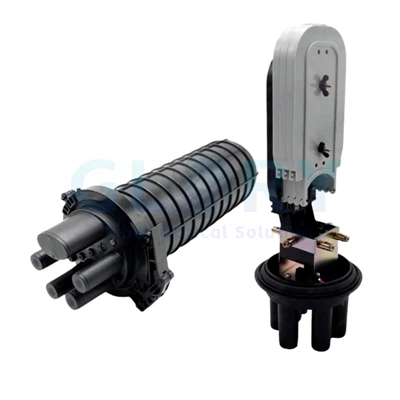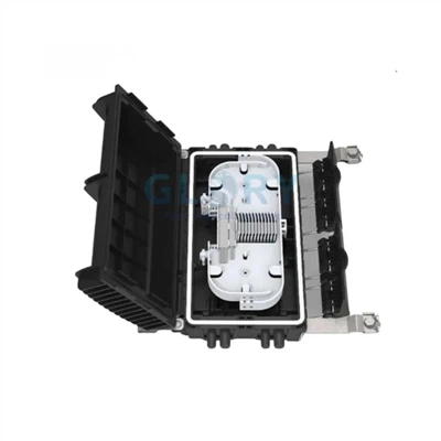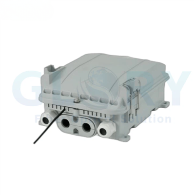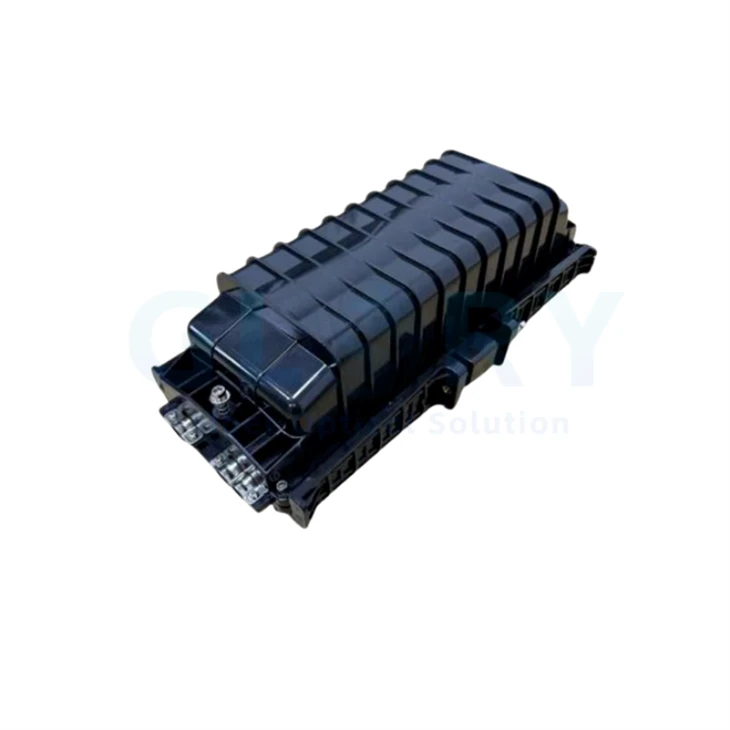

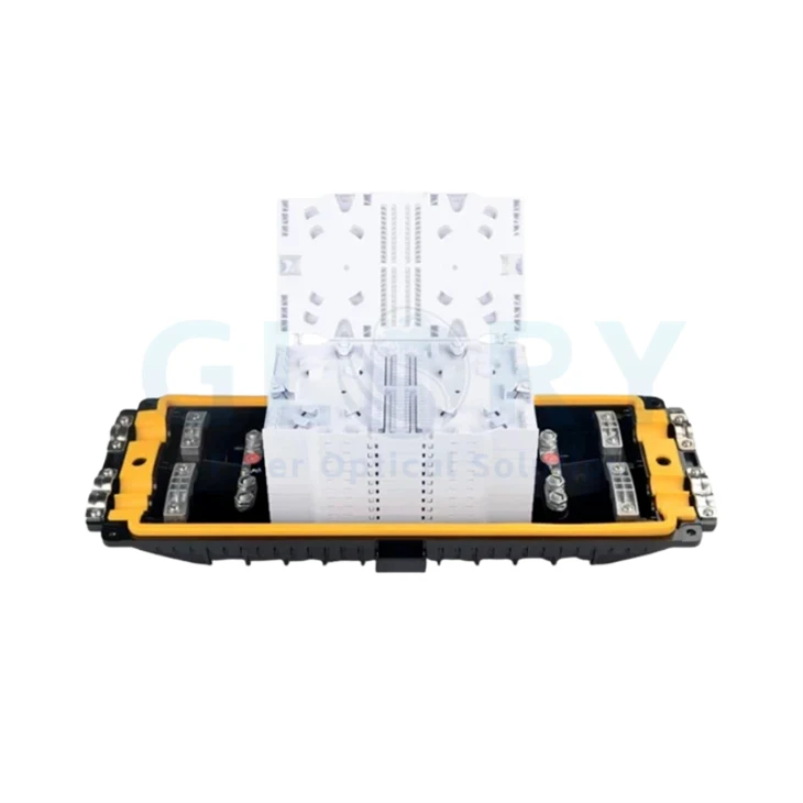


GL-H03 Horizontal Fiber Optic Junction Box Overview
GL-H03 is a compact horizontal splice enclosure that creates protected space for joining and storing optical fibers along an outside-plant cable route. The enclosure belongs to the Fiber Optic Enclosure category and is intended for cable-to-cable splicing rather than subscriber patching or equipment termination.
The polycarbonate shell is specified for outdoor use, with UV and chemical resistance, dust and water protection, and a stated IP68 rating. Its two cable entries accept 7–14 mm outside diameters, while the internal capacity is published as 48 fibers for FTTH, FTTC, CATV, telecom, data-communication and local-area-network routes.
Published Configuration
48-Fiber, Two-Entry Horizontal Closure
- Model GL-H03
- 280 × 200 × 90 mm enclosure
- 48-fiber capacity
- Two cable-entry ports
- Φ7–14 mm cable compatibility
- Polycarbonate plastic housing
- IP68 protection level
- −40°C to +85°C operation

Horizontal Enclosure Profile
A 280 × 200 × 90 mm housing for protected cable joints along aerial and underground OSP routes.

Two-Cable Route
Two entries accept fiber optic cables with outside diameters from 7 mm through 14 mm.

Outdoor Splice Protection
The PC enclosure is specified as IP68 and supports several outside-plant mounting environments.
GL-H03 Fiber Optic Junction Box: Six Engineering Advantages
Published 48-Fiber Capacity
The GL-H03 is specified for 48 fibers in one horizontal enclosure. This gives network designers a defined capacity for cable-joint protection without treating the number as adapter ports or subscriber outputs, helping procurement teams match the housing to the actual splice map.
Two Entries for Φ7–14 mm Cables
Two cable-entry ports accept cable outside diameters from 7 mm to 14 mm. The published range gives installers and buyers a measurable check against the feeder or distribution cable datasheet before the closure is allocated to an aerial, duct or buried route.
IP68 Across −40°C to +85°C
The enclosure is listed at IP68 with an operating range from −40°C to +85°C. Together, these values define the published environmental envelope for exposed or underground splice locations while keeping ingress protection separate from project-specific burial depth, water pressure and duration.
Polycarbonate Shell for Outdoor Routes
The housing uses polycarbonate plastic and is described as UV- and chemical-resistant. Compared with an indoor junction housing, this material specification addresses sunlight and outdoor contaminants at OSP splice points while giving purchasers a stated resin family for BOM and drawing review.
Cut, Uncut and Taut-Sheath Applications
The enclosure may be used where the cable is cut for conventional jointing, remains uncut through the node or is handled as a taut-sheath route. This lets route planners keep one closure format across different cable-access methods, provided the two-entry layout and 48-fiber capacity match the splice plan.
Aerial, Duct, Handhole and Buried Locations
The GL-H03 is listed for aerial, direct-buried, underground, pipeline, handhole, duct and wall-mounted deployment. That mounting range allows the same 280 × 200 × 90 mm enclosure to be evaluated against several route types instead of limiting procurement to a single installation position.
GL-H03 Model and Capacity Table
| Model | Product Type | Fiber Capacity | Cable Entries | Cable Diameter | Dimensions | Protection |
|---|---|---|---|---|---|---|
| GL-H03 | Horizontal fiber optic junction box / fiber splice closure | 48 fibers | 2 | Φ7–14 mm | 280 × 200 × 90 mm | IP68 |
GL-H03 Fiber Optic Junction Box Technical Specifications
General and Environmental Specifications
| Parameter | Published Specification | Engineering Use |
|---|---|---|
| Product model | Fiber Splice Closure GL-H03 | Ordering and drawing identification |
| Product family | Fiber optic enclosure / horizontal splice enclosure | Cable-to-cable splice protection |
| Fiber capacity | 48 fibers | Match to the route splice map |
| Dimensions | 280 × 200 × 90 mm | Check mounting and access space |
| Enclosure material | Polycarbonate plastic | Housing and BOM material reference |
| Protection level | IP68 | Outdoor ingress-protection requirement |
| Operating temperature | −40°C to +85°C | Route environmental range |
| Resistance stated on source page | UV and chemical resistant; dust- and water-protective design | Outdoor material and enclosure review |
| Application environment | Aerial, direct buried, underground, pipeline, handhole, duct and wall mounting | Outside-plant placement |
Cable and Route Compatibility
| Compatibility Item | Published Range or Application | Selection Check |
|---|---|---|
| Cable-entry count | 2 pieces | Map incoming and outgoing cable routes |
| Cable outside diameter | Φ7–14 mm | Compare with the actual cable datasheet |
| Cable-access method | Cut, uncut and taut-sheath applications | Define the field access method in the work plan |
| Network types stated | FTTH, FTTC, CATV, optical access, telecom, data communications and LAN | Use at a protected cable-splice node |
| Mounting environments | Aerial, direct buried, underground, pipeline, handhole, duct and wall | Match site hardware and access space to the installation |
Fiber Optic Junction Box Applications and OSP Solutions
48-Fiber Optic Junction Box for Aerial Distribution
An exposed cable joint without a route-matched closure leaves fusion splices vulnerable to sunlight, moisture and movement along the span. The GL-H03 places up to 48 fibers inside a polycarbonate, IP68 horizontal housing at an aerial FTTH or FTTC feeder-to-distribution joint. Its two entries accept 7–14 mm cables and support cut, uncut or taut-sheath access. Before purchasing, compare the actual cable outside diameter and fiber-level splice map with the published entry range and capacity, then define the aerial attachment hardware and service-access position for the project.
Horizontal Closure for Duct and Pipeline Cable Joints
A closure selected only by fiber count can still be difficult to place when the duct route, cable direction and available access space are ignored. The 280 × 200 × 90 mm GL-H03 follows a horizontal two-entry layout for protected inline splicing inside duct or pipeline networks. It accepts 7–14 mm fiber optic cables and is specified at IP68 for outdoor routes. Procurement should provide the duct or chamber dimensions, cable outside diameter, entering and leaving directions, 48-fiber splice plan and the intended method for securing the enclosure without loading the cable entries.
IP68 Fiber Optic Junction Box for Handholes
Underground access points can collect dust and water, while a poorly sized enclosure may obstruct cable slack or future re-entry. The GL-H03 uses a PC housing with a stated IP68 level and −40°C to +85°C operation for handhole and underground splice locations. Its two ports carry 7–14 mm cables into a 48-fiber horizontal joint enclosure. Buyers should document the chamber size, possible water exposure, cable route and bend requirements, attachment point, splice count and maintenance access before assigning the model to an underground OSP bill of materials.
GL-H03 Closure for Direct-Buried and Wall-Mounted Routes
Using the same installation assumption for a buried route and a building wall can result in unsuitable fixing hardware, cable strain or inaccessible splice storage. GL-H03 is listed for both direct-buried and wall-mounted deployment, using a UV- and chemical-resistant polycarbonate shell to protect cable joints in FTTH, CATV, telecom, data-communication and LAN routes. The selected fiber cables must remain within the 7–14 mm entry range. Before release, identify the mounting environment, cable-access method, burial or wall conditions, 48-fiber capacity requirement and site-specific attachment method.
Fiber Optic Junction Box Selection and Installation Guidance
Start with the Fiber-Level Splice Map
Count the real through, branch and restoration splices at the node, then compare the result with the published 48-fiber capacity. Do not treat fiber capacity as adapter quantity, splitter outputs or subscriber ports.
Check Both Cable Outside Diameters
Record the manufacturer-stated outside diameter of each entering cable. Both cables must fit the published Φ7–14 mm range, and the route plan must use the two available entry positions.
Define Cable Access and Network Position
State whether the route uses cut, uncut or taut-sheath access and whether the box forms an inline joint or branch point. This controls cable preparation, slack planning and field work instructions.
Match the Site to the Enclosure
Use the published IP68 and −40°C to +85°C values together with the actual aerial, duct, handhole, buried or wall environment. Specify mounting hardware and site exposure in the project installation plan.
Ordering Configuration
| RFQ Field | Information to Send | Procurement Purpose |
|---|---|---|
| Model and quantity | GL-H03 and required order quantity | Identifies the base enclosure and batch size |
| Network node | Inline joint, branch point or other splice position | Connects the product to the cable route |
| Fiber plan | Incoming fiber count, outgoing fiber count and real splice count | Checks the published 48-fiber capacity |
| Cable information | Cable type, manufacturer, construction and outside diameter | Checks compatibility with the two Φ7–14 mm entries |
| Cable access | Cut, uncut or taut-sheath method | Defines cable preparation and routing |
| Installation environment | Aerial, direct buried, underground, pipeline, handhole, duct or wall | Defines site exposure and access conditions |
| Mounting details | Site drawing, fixing surface and installation-hardware requirement | Aligns enclosure placement with the project method |
| Identification | Model label, project code, route ID and logo requirement | Supports field identification and repeat orders |
| Packaging and documents | Label format, packing instruction, drawing and requested inspection records | Sets shipment and document deliverables |
OEM Fiber Optic Junction Box and Project Configuration
Glory Optical's company page states that OEM/ODM support can cover housing structure, cable-entry design, color, logo, labeling, packing, splice-tray layout and sample confirmation. For an OEM GL-H03 project, use the published model data as the starting point and place every requested change in the drawing, BOM and sample record.
Enclosure and Cable-Entry Review
Provide the route drawing, cable outside diameters, entry direction, fiber count and cable-access method. Glory can review the housing and entry arrangement against the project installation environment.
Splice Arrangement and Sample
Supply the splice map, fiber type, protector format and reserve requirement so the internal arrangement can be shown in a drawing or sample before repeat production.
Logo, Labels and Packaging
Project codes, route labels, customer branding and packaging can be placed into the approved order specification to keep field identification and repeat-batch packing consistent.
Why Glory Optical for Fiber Optic Junction Box Supply
Glory Optical Communication is a Ningbo-based manufacturer of passive fiber optic infrastructure for FTTH access, ODN field deployment and outside plant. The current company page states that Glory was founded in 2008 and operates a 20,000 m² facility supporting R&D, molding, enclosure assembly, sample preparation, inspection, packing and project supply.
Mold and Enclosure Control
Glory's company page describes tooling and mold development used to control enclosure geometry, gasket position, port cutouts and structural details before production. These controls are directly relevant when a junction-box project changes the standard housing or cable-entry arrangement.
Drawing-Based Batch Review
Incoming material inspection, dimensional checks, assembly review and packing inspection are performed against the confirmed specification, drawing and packing requirement. Outdoor-product sealing checks can be applied according to the product specification.
Samples, Labels and Documents
Project support can include samples, product drawings, labels, packing photos, test reports and applicable compliance documents. The required files should be listed with the RFQ so the document package follows the approved GL-H03 order configuration.
Commercial Support Listed on the Current Product Page
| Support Item | Current Page Statement |
|---|---|
| Standard MOQ | 50 units |
| Sample support | Free samples are offered for product evaluation |
| Standard-item delivery | Delivery within 10 days is listed for standard items |
| Service policy | Return support in year one, replacement support in year two and repair support in year three for quality issues |
| Project workflow | Drawing review, specification review, sample planning, inspection, packing and batch supply |
From sample verification to project configuration
Confirm the physical interface and cable code before bulk production, then lock the approved configuration into drawings and order codes.
3-Year Service Policy
Defined return, replacement and repair support is available according to the applicable warranty terms and confirmed order documentation.
OEM/ODM Configuration
Port count, cable length, splitter structure, mounting accessories, labeling and packaging can be configured for the project.
Sample & Drawing Approval
Sample evaluation and approved drawings help confirm interface fit, sealing and cable compatibility before volume deployment

Our Quality Promise
Comprehensive 3-Year Warranty
We confidently back all our products with a 3-year warranty. Our specific service policy is: within one year for quality issues, we take full responsibility for returns; within two years, for replacements; and within three years, for repairs.
Clear & Competitive MOQ
We welcome both trial and bulk orders. Our standard Minimum Order Quantity (MOQ) is 50 units. We also offer free samples for testing to help you evaluate our quality with confidence.
Fast & Reliable Logistics
We guarantee delivery within 10 days for standard items. Our logistics advantage includes cost-effective door-to-door service to simplify shipping for you.
Our Foundation
Backed by 18 years of experience since 2008, we control quality from our own factory, accept OEM/ODM requests, and maintain ready stock for wholesale. We focus on delivering the optimal balance of price and quality directly to end customers worldwide.
Your trust is our priority. Partner with us for dependable fiber optic solutions supported by clear promises.
Hot Tags: gl-h03 48-fiber optic junction box, China gl-h03 48-fiber optic junction box manufacturers, suppliers, factory, 24 Port Fiber Termination Box, fiber optic cable termination box, fiber optic termination box, fiber optic termination cabinet, Fiber Termination Enclosure, outdoor fiber distribution box