Quick Answer: When Should You Use Pre-Terminated Fiber?
Pre-terminated fiber is a strong choice when the installed pathway can be surveyed, the route length is stable, the pulling package fits every opening, connector and polarity requirements are confirmed, and reducing field splicing creates measurable schedule value.
A one-end-terminated or field-spliced design is usually safer when the route remains uncertain, construction changes are continuing, or the connector package cannot pass through the available pathway.
A custom assembly arrives with a fixed length, connector configuration, breakout structure, polarity and pulling arrangement. Commercial success therefore depends on coordinating the route, pulling head, termination hardware, bill of materials and acceptance evidence before manufacturing begins.
Survey the Route Before Releasing the Order
Factory termination moves several installation decisions into the manufacturing stage. Route measurement becomes critical because the finished assembly cannot be shortened or extended as easily as unterminated bulk cable.
Corning SRP 005-014 recommends surveying the cable route, inspecting pull boxes, verifying conduit assignments and confirming pathway suitability before installing factory-connectorized cable. The procedure also emphasizes the importance of cut length for preconnectorized assemblies.
Measure the Installed Path
Architectural drawings provide a starting point, but they may omit rack entry paths, riser transitions, construction changes, cabinet routing, pull-box loops and maintenance access. Measure along the centerline of the route the cable will actually follow.
| Survey item | Information to record | Commercial consequence if missing |
|---|---|---|
| Start and end points | Rack, cabinet, terminal or enclosure IDs | Wrong breakout or labeling configuration |
| Pathway length | Measured centerline distance | Assembly too short or excessive slack |
| Smallest pathway | Verified clear inside diameter | Pulling head cannot pass |
| Bends | Quantity, angle and accessibility | Unexpected tension or blocked pull |
| Pull boxes | Dimensions and working access | No room to manage connectors or back-feed cable |
| Existing occupancy | Cables, obstructions and internal damage | Clear diameter overstated |
| Equipment routing | Pathway exit to final port | End routing omitted from cut length |
| Slack locations | Planned storage at both ends | Uncontrolled coils inside cabinets |
| Pulling direction | Reel position and approved pulling end | Wrong pulling-eye orientation |
| Environment | Indoor, outdoor, wet, UV or burial exposure | Incorrect jacket or cable construction |
Use a Route Release Gate
A route should pass four checks before the order moves into production: measured length, pulling-package clearance, workable handling points and adequate termination space.

Calculate the Order Length by Component
| Length component | Example value | Where the allowance is used |
|---|---|---|
| Measured pathway | 82 m | Verified centerline route |
| Rack and cabinet routing | 5 m | From pathway exit to final ports |
| Planned service access | 6 m | Defined maintenance and termination locations |
| Installation positioning allowance | 2 m | Controlled final positioning |
| Specified assembly length | 95 m | Released manufacturing length |
Every allowance needs a confirmed storage or working location. Adding a generic percentage without checking available space can create large coils, blocked labels and poor cabinet access.
For detailed length selection outside this article's route-survey scope, refer to Glory's Fiber Patch Cable Length Guide.
Design Pulling Protection Around the Connector Package
Connectors and breakout legs need mechanical isolation during pulling. The pulling assembly should transfer tensile force into approved cable strength members while shielding connector bodies from abrasion, impact and twisting.
Define the Pulling Interface in the RFQ
Drawing information
- Factory pulling eye required or not required
- Approved pulling end
- Maximum pulling-head outside diameter
- Pulling-eye length and protective sleeve design
- Connector staggering arrangement
Installation limits
- Maximum approved pulling tension
- Swivel requirement
- Reel pay-off direction
- Permitted pulling orientation
- Removal procedure after installation
Corning specifies that pulling grips for preconnectorized cable should isolate connectors from tensile load and place the pulling force on the cable. Staggered connectors can reduce the profile of a multi-fiber pulling package.
Compare the Entire Pulling Package with the Route
The main cable diameter rarely represents the largest installation dimension. The connector group, dust caps, breakout tubing, protective wrapping, transition body and pulling eye can determine whether the assembly passes through the route.
Attribution of the 0.65 ratio
This article uses 0.65 as a Glory quotation-stage screening trigger. It is an internal preliminary-review value and is not derived from Corning, FOA, TIA, IEC or a conduit-fill standard. It identifies projects that require more engineering information before quotation approval.
| Pulling-head OD | Clear pathway ID | Ratio | Glory preliminary action |
|---|---|---|---|
| 25 mm | 50 mm | 0.50 | Continue route review |
| 32 mm | 50 mm | 0.64 | Engineering review |
| 38 mm | 50 mm | 0.76 | Validate route or redesign assembly |
Keep Bend-Radius Coverage Focused on the Pull
During cable placement, follow the assembly datasheet for maximum installation tension, loaded bend radius, pulling-grip rating, swivel load and permitted pulling direction. Stop the pull when resistance changes unexpectedly and locate the obstruction before applying more force.
This guide stays focused on connector protection and route handling. Fiber grades, static versus dynamic radius, macrobend loss and cable-specific calculations are covered in Glory's dedicated Fiber Optic Cable Bend Limits Guide, which should remain the primary internal page for bend-radius searches.
Select Cable, Connectors and Termination Hardware as One System
The assembly must match the transmission requirement and the physical installation. Fiber type, cable construction, connector interface, polarity and termination hardware should be approved together.
| Application | Typical starting configuration | Key checks |
|---|---|---|
| FTTH drop | G.657.A2 OS2 | Terminal interface, compact route and outdoor exposure |
| Campus backbone | OS2 indoor/outdoor | Building entry and fire-rating transition |
| Industrial network | Armored OS2 | Crush, chemical and temperature exposure |
| Enterprise data center | OM4 or OS2 | Transceiver type and migration plan |
| High-density data center | MPO/MTP OS2 or OM4 | Fiber count, polarity and panel architecture |
The cable specification should identify fiber type, fiber count, cable construction, outside diameter, jacket, fire rating, water blocking, UV resistance, armoring and installation temperature. Browse Glory's fiber optic cable range when a project requires a route-specific construction.
Lock the Connector and Polarity Interfaces
- Connector family and simplex, duplex or multi-fiber format
- UPC or APC polish
- Male or female configuration where applicable
- Key orientation and complete port map
- Breakout length and boot direction
- Adapter, cassette, patch-panel or terminal compatibility
Glory's Fiber Optic Connectors Guide should remain the primary internal resource for LC, SC, APC and UPC comparisons. For high-density assemblies, refer to the MTP vs MPO guide.
Build a Quote-Ready Pre-Terminated Fiber BOM
A usable BOM connects the cable assembly with the termination hardware, installation accessories and acceptance documents needed to place the link into service.
| BOM field | Required information | Why it affects production |
|---|---|---|
| Link ID | Unique route and assembly reference | Controls labeling and traceability |
| Quantity | Number of identical assemblies | Controls production batch |
| Length | Manufactured cut length and tolerance | Locks material and packaging |
| Fiber | Type, grade and count | Defines transmission and capacity |
| Cable | Construction, OD and jacket | Defines route compatibility |
| End A / End B | Connector, polish, breakout and labels | Defines termination and pulling profile |
| Polarity | Method and complete port map | Prevents channel reversal |
| Pulling protection | Pulling end, OD and load rating | Defines installation interface |
| Environment | Indoor, outdoor, wet, UV or burial | Defines cable material |
| Optical limits | Required insertion and return loss | Defines factory acceptance |
| Packaging | Coil or reel and pay-off direction | Supports route handling |
| Documentation | Drawing, report, polarity record and packing list | Supports approval and closeout |
Example 24-Fiber OS2 Campus BOM
- One custom-length 24-fiber OS2 pre-terminated trunk
- One factory pulling eye on the approved pulling end
- Two rack-mount fiber patch panels
- Two compatible breakout modules or cassettes
- Equipment-side LC patch cords
- Port and route labels
- Factory insertion-loss and polarity report
- Field OLTS results for every fiber
- Bidirectional OTDR traces when required
- Connector inspection records
Glory Optical Products for Pre-Terminated Projects
Product selection should follow the verified route. The following Glory products illustrate different ways to reduce field termination while matching conduit, outdoor and high-density requirements.
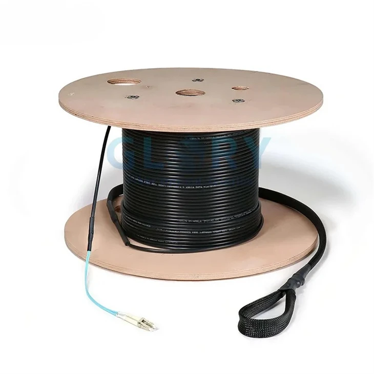
Conduit and outdoor routes
Outdoor Fiber Patch Cord with Pulling Sheath
Built-to-length cable assembly with a protective pulling aid for raceway, conduit, telecom and industrial installations. The product page publishes cable and pulling-aid dimensions so route clearance can be reviewed before ordering.
Real product image from the Glory Optical product page.
View product
Restricted indoor pathways
Pushable/Pullable Patch Cable Fiber
A compact pre-connectorized format designed for wall channels and restricted routes where a conventional connector body would require a larger opening.
Real product image from the Glory Optical product page.
View product
FTTH and outdoor interconnection
Outdoor Single Mode Fiber Patch Cord
G.657A2 OS2 assemblies for outdoor and access-network applications, available with project-specific connector, jacket and protection options and per-unit optical test documentation.
Real product image from the Glory Optical product page.
View product
High-density data centers
MPO to MPO Fiber Cable
A factory-terminated high-density trunk option for modular patching systems. Specify fiber count, fiber type, connector gender, polarity, jacket and length before production.
Real product image from the Glory Optical product page.
View productUse a Controlled Installation and Acceptance Workflow
Incoming inspection
- Confirm route ID and manufactured length
- Compare both ends with the approved drawing
- Inspect pulling eye and reel pay-off direction
- Review factory reports and package condition
Route preparation
- Verify pathway continuity and pull-box access
- Remove sharp edges and install guides
- Confirm pulling limits and stop signals
- Prepare approved slack-storage locations
Cable placement
- Connect only to the approved pulling interface
- Use a swivel when specified
- Monitor resistance and tension
- Stop when resistance changes unexpectedly
Closeout
- Inspect breakout legs and connector boots
- Store slack without deformation
- Apply consistent link and port labels
- Retain supplier serial numbers
Test the Installed Link
Factory reports document assembly performance before shipping. Field testing verifies condition after transport, pulling, routing and connector mating.
Inspect and Clean Connector End Faces
IEC 61300-3-35:2022 covers observation and classification of debris, scratches and defects on fiber-connector end faces. Visual inspection supports optical testing but does not replace attenuation or return-loss measurements.
Use OLTS for End-to-End Loss
The acceptance plan should define wavelengths, reference method, test-cord configuration, testing direction, maximum allowable loss, fiber identification and reporting format before installation begins.
Use OTDR for Event-Level Evidence
OTDR testing can document installed fiber length, connector events, abnormal loss locations and a maintenance baseline. OLTS should remain the principal end-to-end loss record, while OTDR adds diagnostic and location information.
Create a Cable Acceptance Record
| Record group | Required evidence |
|---|---|
| Identity | Link ID, supplier serial number and installation date |
| Approved configuration | Production drawing, cable specification and port map |
| Factory evidence | Insertion loss, return loss and polarity results |
| Field evidence | OLTS results, OTDR traces where required and inspection records |
| Closeout evidence | Photos, deviations, repairs and approved changes |
Send a Route Schedule, Not Just a Cable Name
For a project-specific quotation, provide the measured route, smallest opening, fiber count, cable construction, connector interfaces, polarity, pulling-head limit, supporting hardware and acceptance requirements. Glory Optical can review these dependencies before production.
View Pre-Terminated Assemblies Request a QuoteFrequently Asked Questions
Q: Can pre-terminated fiber be pulled through conduit?
A: Yes, when the route is verified, the complete pulling package fits, approved pulling protection is used and the assembly installation limits can be maintained.
Q: What conduit size is required?
A: Conduit size depends on the maximum pulling-head diameter, clear pathway inside diameter, bends, occupancy, pulling distance and access points. Fiber count alone cannot determine the answer.
Q: How much extra cable should be ordered?
A: Add equipment routing, planned working access, controlled slack and a defined installation allowance to the measured pathway. Each allowance needs a confirmed storage or working location.
Q: Does Corning require three meters of slack at every end?
A: No. Corning SRP 005-014 describes enough cable to reach a convenient work surface plus approximately three meters of working length. The statement should not be converted into a universal service-loop rule.
Q: Should one or both ends be factory terminated?
A: Two-end termination works well on stable and accessible routes. One-end termination reduces the pulling profile and allows more flexibility where access is restricted.
Q: Is OTDR testing mandatory?
A: The project specification determines the requirement. OLTS confirms total end-to-end loss, while OTDR adds event location and diagnostic evidence.
Q: Can pre-terminated cable be used outdoors?
A: Yes, provided the cable construction, jacket, water blocking, mechanical design and connector system match the actual installation environment.
Referenced Standards and Technical Sources
- Corning Standard Recommended Procedure 005-014 - route survey, cut-length planning, connector staggering, pulling grips and working-length context.
- IEC 61300-3-35:2022 - visual inspection of fiber connector end faces.
- ANSI/TIA-568.3-E - optical-fiber cabling components and connectivity requirements.
- NECA/FOA 301-2016 - installation, continuity, OLTS, OTDR and documentation guidance; verify current contractual status before specifying.
- Glory Fiber Optic Cable Bend Limits Guide - primary internal resource for bend-radius values and macrobend behavior.
Final Procurement Principle
Pre-terminated fiber performs best when route measurements, assembly design, termination hardware and acceptance evidence are approved together. A complete RFQ gives the factory enough information to manufacture a cable that fits the pathway, protects its connectors during installation and arrives with records that can be matched to the installed link.