Open any optical distribution frame in the world, and you will find them: short lengths of fiber with a connector on one end and bare glass on the other. Fiber pigtails are the most terminations in the industry, yet they rarely get the attention they deserve. The truth is, this unassuming component sits at the exact junction where factory precision meets field reality, and getting it wrong is the fastest way to turn a clean link budget into a troubleshooting nightmare.
The Unseen Workhorse: What a Pigtail Actually Does
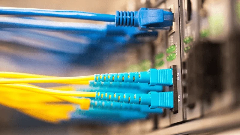
A fiber optic pigtail is a short cable, typically 0.5 to 2 meters, with a factory-terminated connector on one end and bare, exposed fiber on the other. The connector end plugs into an adapter panel, a splitter, or active equipment. The bare end gets fusion-spliced to an incoming trunk or distribution cable inside a splice tray. That is the entire job description, and it sounds deceptively simple.
What makes the pigtail indispensable is where it sits in the network topology. Every fiber network has a transition point where the ruggedized outside-plant cable, pulled through conduits and up risers, must connect to the clean, connectorized world of patch panels and transceivers. You cannot terminate a 144-fiber ribbon cable directly onto an ODF faceplate. You need something that bridges the two worlds, and that something is the pigtail.
The pigtail's value proposition comes down to one engineering insight: the connector end is polished under controlled factory conditions, where temperature, humidity, and particulate contamination are tightly managed. The bare fiber end is joined to the field cable via fusion splicing, which itself is a highly repeatable process. The result is a termination that combines factory-grade connector geometry with field-adaptable cable length, something neither a field-terminated connector nor a pre-terminated patch cord can deliver alone.
Industry estimates suggest pigtails are used in roughly 99% of single-mode fiber termination applications worldwide. That is not because they are glamorous. It is because they solve a real problem more cost-effectively than any alternative.
The Factory-Polished Advantage: Why Controlled Environment Beats Field Termination
To understand why pigtails dominate, you need to understand what happens when you try to polish a connector in the field. Field termination kits exist, and they work, but they ask a technician to replicate, on a street corner or inside a manhole, what a factory does with automated polishing machines in a cleanroom.
A factory-polished connector typically achieves an insertion loss of 0.1 to 0.3 dB and a return loss of 50 dB or better (UPC) or 60 dB or better (APC). The ferrule end-face geometry, the radius of curvature, the apex offset, and the fiber undercut are all controlled to micron-level tolerances by automated equipment. When a technician polishes by hand, the variance increases dramatically. The same connector that would have passed in the factory might show 0.5 dB insertion loss or 35 dB return loss, and you will not know until you test it.
There is also a cost dimension. A factory-terminated pigtail can cost up to 33% less than an equivalent pre-polished field connector, because the factory process is faster, more automated, and benefits from economies of scale. The field connector carries a premium for the mechanical alignment sleeve and the pre-cleaved stub fiber inside it. So the pigtail wins on both performance and price, which is why it has become the default.
The one trade-off is that fusion splicing requires a splicing machine. A quality fusion splicer costs $1,500 to $8,000 or more. But that machine is a one-time investment that serves thousands of splices over its lifetime. Once you have it, the per-splice cost drops to just the consumables, which is negligible. For any organization doing more than a handful of terminations, the fusion splicer pays for itself quickly.
Pigtail vs. Patch Cord: More Than Just "One Connector vs. Two"
The distinction between a pigtail and a patch cord is often explained as "one connector vs. two," but that shorthand obscures a deeper architectural difference. A patch cord is a temporary, pluggable connection between two already-terminated ports. A pigtail is a permanent, spliced transition between a bulk cable and a connectorized interface. They serve different layers of the network, and confusing them leads to spec errors.
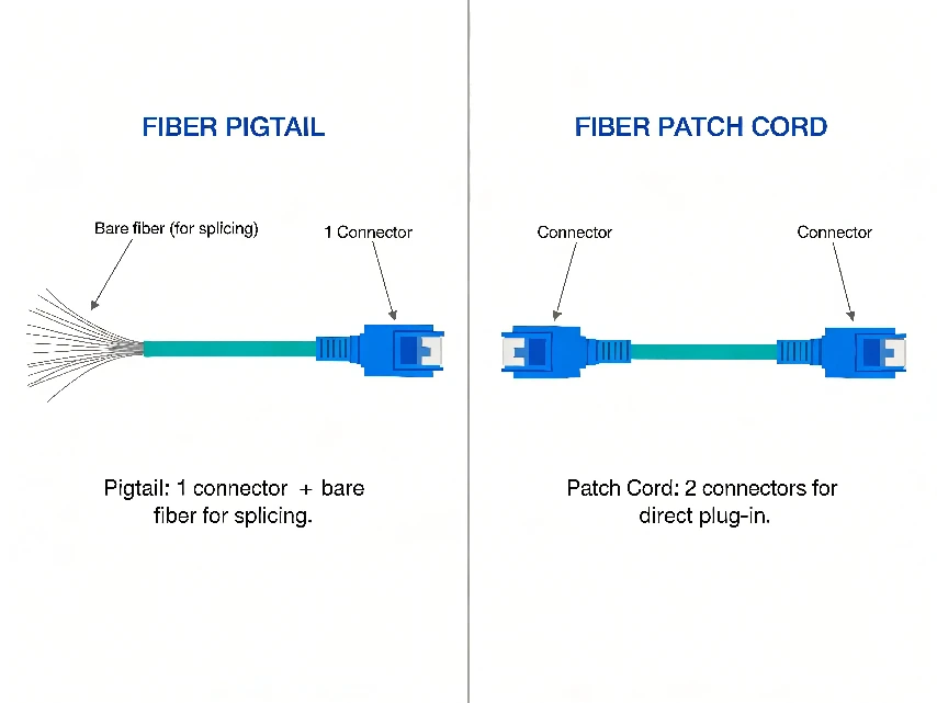
Here is a practical way to think about it. When a 200-meter OS2 cable enters a building from a buried conduit, you cannot simply plug a patch cord into its end. The cable has no connector. You need to splice a pigtail onto it, and that pigtail's connector then seats into an adapter panel. From that panel, a patch cord runs to the switch. The pigtail is the fixed infrastructure layer; the patch cord is the flexible interconnect layer. Removing a patch cord is trivial. Replacing a spliced pigtail requires re-splicing, which is why pigtails are specified more carefully and installed with more permanence in mind.
One installer trick worth knowing: if you need pigtails in the field and only have patch cords on hand, you can cut a tested, certified patch cord down the middle to produce two pigtails. You already know the connector end-face quality is good because the factory tested it. You only need to verify the splice performance afterward. This is not ideal, but it works in a pinch, and it illustrates the fundamental relationship between the two products.
Connector and Polish Selection: A Failure-Driven Approach
Most pigtail selection guides list connector types and polish types in a table and leave it at that. But the real question is not "which connector should I use?" It is "which failure mode am I trying to prevent?" That question leads to better decisions.
The Polish Decision: APC vs. UPC
The choice between APC (Angled Physical Contact) and UPC (Ultra Physical Contact) polish is the single most consequential pigtail specification, and it is also the most commonly misunderstood. The difference is not about quality. It is about back reflection management.
UPC connectors have a flat, super-polished end-face that achieves a return loss of about 50 dB. That is adequate for standard digital data links where the transceiver can tolerate moderate reflection. APC connectors have an 8-degree angled end-face that deflects reflected light away from the fiber core at roughly 16 degrees, achieving 60 dB or better return loss. This matters enormously in PON networks, where upstream traffic from the ONU arrives in burst-mode transmissions. Even small reflections back into the burst-mode receiver can raise the noise floor and degrade the signal-to-noise ratio.
The Connector Decision: SC, LC, and What Comes Next
For FTTH and PON work, SC/APC pigtails are the default worldwide. The push-pull mechanism is easy to operate in field conditions, and the installed base of SC-compatible equipment is enormous. For data centers, LC/UPC pigtails dominate because their 1.25 mm ferrule is half the footprint of SC, allowing twice the port density in the same panel space.
For test equipment and vibration-prone environments, FC connectors with threaded metal bodies resist loosening better than snap-in types. For European carrier networks, E2000 connectors with integrated shutters provide laser safety and are mandated by some operators. ST connectors, once the standard for multimode LANs, are being phased out in favor of LC but still appear in legacy installations.
The Splicing Decision: Fusion vs. Mechanical, Beyond the Spec Sheet
Once you have selected the pigtail, the bare fiber end must be permanently joined to the incoming cable. There are two methods: fusion splicing and mechanical splicing. The spec sheet comparison is straightforward, but the real-world decision involves factors that do not appear on any data sheet.
Fusion Splicing: The Gold Standard
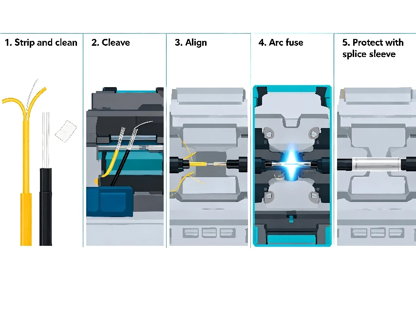
Fusion splicing uses an electric arc to melt and fuse two cleaved fiber ends together. When done correctly, the splice point is essentially seamless, the glass of the two fibers becomes one continuous strand. Insertion loss is typically 0.01 to 0.05 dB, and back reflection is virtually zero. The FOA recommends a planning value of 0.15 dB per single-mode fusion splice for loss budget calculations, but skilled technicians routinely achieve results below 0.1 dB.
The trade-off is the upfront investment in a fusion splicer. But here is the part that does not appear on the spec sheet: a fusion splice is a permanent weld. It will not shift, degrade, or drift from vibration, thermal cycling, or cable tension the way a mechanical alignment can. In outside plant closures that sit in manholes for 20 years, this permanence is not a luxury. It is a requirement. Mechanical splices, by contrast, use index-matching gel that can dry out or migrate over time, especially under temperature extremes.
Mechanical Splicing: When It Makes Sense
Mechanical splicing uses a precision alignment sleeve filled with index-matching gel to hold two cleaved fiber ends in contact. No heat, no expensive machine. Installation takes 1 to 3 minutes per splice, compared to 2 to 5 minutes for fusion. The trade-off is performance: mechanical splices typically introduce 0.2 to 0.5 dB of insertion loss and have higher back reflection.
Mechanical splicing makes sense in three scenarios. First, emergency repairs where a fusion splicer is not available. Second, small-volume work where the splicer cost cannot be amortized. Third, indoor LAN applications where the link budget has enough margin to absorb the extra loss and the environment is benign. For anything else, especially outside plant and long-haul single-mode, fusion splicing is the right answer.
Where Pigtails Live: From FTTH Cabinets to AI Data Centers
The pigtail's role changes depending on where it sits in the network. Understanding these deployment contexts is essential for specifying the right product.
FTTH and PON Networks
In FTTH, GPON, and XGS-PON deployments, single-mode SC/APC pigtails terminate drop cables inside fiber distribution boxes and PLC splitter outputs. The APC polish is essential here because PON upstream traffic uses burst-mode transmission between the ONU and the OLT. Back reflection from a UPC connector can raise the noise floor of the burst-mode receiver, degrading the signal-to-noise ratio. In a street-level splitter cabinet, you might find dozens of SC/APC pigtails, each fusion-spliced to a drop cable and seated into a splitter module.
Data Centers
Data centers use LC/UPC OS2, OM3, or OM4 pigtails to splice backbone cables to panels and cassettes. High-density environments prefer 0.9 mm buffered LC pigtails for MPO/MTP breakout cassettes. A growing number of AI training clusters are specifying OM5 pigtails for short-wavelength division multiplexing (SWDM) applications, and 400G/800G switch ports are driving adoption of VSFF connectors that pack more fibers into the same panel space.
5G Fronthaul and Smart Grid
5G fronthaul and smart grid networks use armored or waterproof pigtails in street cabinets and utility poles. These links need to survive vibration, temperature swings, and moisture while keeping loss low. The typical specification is 3.0 mm buffered SC/APC OS2 pigtails with PE jacket, rated for -40 degrees C to +75 degrees C. The thicker buffer provides strain relief at cable entry points, and the PE jacket handles UV exposure that would degrade PVC in months.
Industrial and Outdoor Closures
Railway, utility, and factory networks use 3.0 mm buffered FC or ST pigtails in splice closures exposed to vibration or wide temperature swings. The threaded FC body resists loosening from vibration far better than snap-in connectors. In rodent-prone areas, armored pigtails with stainless steel tubes eliminate the need for separate innerduct, which can save significant installation labor cost.
The VSFF Revolution: How 400G and 800G Are Reshaping Pigtail Design
The most significant shift in pigtail design over the past three years is the rise of Very Small Form Factor (VSFF) connectors. As AI data centers deploy 400G, 800G, and now 1.6T optics, traditional LC duplex connectors are running out of physical space on switch faceplates.

VSFF connectors, including SN (developed by SENKO), CS, and MDC, occupy roughly one-quarter to one-third the footprint of an LC duplex connector. The SN connector, for example, is a recommended QSFP-DD MSA duplex option and is widely used for 400G and 800G breakout applications. CS connectors are designed for QSFP-DD and OSFP module ports. MDC connectors use a push-pull mechanism with a 3.8 mm pitch, the smallest currently available.
What does this mean for pigtail selection? In AI cluster buildouts, where a single rack might have 48 to 64 fiber ports on the top-of-rack switch, VSFF pigtails allow twice the fiber density in the same patch panel. This is not a minor optimization. It is the difference between fitting the cabling in one rack row or two. But VSFF pigtails are still early in their adoption cycle, with limited supplier options and higher per-unit cost. For most enterprise and telecom work, LC remains the practical default.
Five Field Mistakes That Defeat Even the Best Pigtail
You can specify the perfect pigtail and still fail in the field. After analyzing installation failure data and consulting with deployment teams, five mistakes account for the majority of pigtail-related problems.
|
Mistake 1: Mismatched Buffer Diameter Forcing a 3.0 mm pigtail into a splice tray designed for 0.9 mm fiber creates microbends that attenuate the signal. The reverse is also problematic: a 0.9 mm pigtail in a tray designed for 2.0 mm may lack strain relief. Always check the tray's rated buffer diameter before ordering. This sounds obvious, but it is the single most common procurement error. |
|
Mistake 2: Mixing Fiber Types in the Same Link Splicing a single-mode OS2 pigtail to a multimode OM3 cable, or vice versa, creates a core diameter mismatch (9 micrometers vs. 50 micrometers) that results in 10+ dB of insertion loss. The link will fail every power budget test. Always confirm the existing infrastructure before ordering pigtails. Yellow jacket means OS2 single-mode. Aqua means OM3. Violet means OM4. Lime green means OM5. |
|
Mistake 3: Skipping the Clean and Inspect Step A dirty connector end-face is the top cause of high-loss splices and failed certification. Dust, oil, or a microscopic scratch on the ferrule end-face can add 0.5 dB or more of loss. The fix is simple and costs nothing: clean every connector with a fiber cleaning tool and inspect it under a fiberscope before splicing or mating. Yet this step is skipped in the field more often than anyone wants to admit. |
|
Mistake 4: Violating Bend Radius Standard single-mode fiber has a minimum bend radius of 10 mm under tension. Violating this, especially when routing pigtails in tight splice trays, causes macrobend loss that can range from 0.2 dB to complete signal loss. Bend-insensitive G.657.A2 fiber tolerates 7.5 mm, but even that has limits. When storing excess pigtail length in a tray, use the designed routing grooves, not tight loops. |
|
Mistake 5: Ignoring Splice Protection Sleeves The fusion splice itself is strong, but the bare fiber on either side of it is fragile. A splice protection sleeve (heat-shrink tube with a rigid inner rod) must be applied over every splice point. Without it, the splice will survive a few weeks, then fail when the tray is disturbed or the closure experiences thermal cycling. Skipping splice sleeves to save 30 seconds per splice is a false economy that guarantees a return visit. |
The Selection Framework: Matching Pigtail to Purpose
Bringing all of this together, here is a practical framework for selecting the right pigtail for each deployment scenario. The goal is to move from "what connector do I need?" to "what combination of fiber, connector, polish, buffer, and jacket will survive in this environment?"
|
Deployment Scenario |
Fiber & Connector |
Polish |
Buffer |
Jacket |
|
FTTH / PON drop |
OS2, SC |
APC (green) |
0.9 / 2.0 mm |
LSZH / PVC |
|
Data center ODF |
OS2 / OM4, LC |
UPC (blue) |
0.9 mm |
LSZH |
|
AI cluster 400G/800G |
OS2 G.657.A2, SN/CS |
UPC |
0.9 mm |
LSZH |
|
5G fronthaul / street |
OS2, SC |
APC (green) |
3.0 mm |
PE (outdoor) |
|
Industrial / vibration |
OS2, FC |
UPC / APC |
3.0 mm |
Armored |
|
Test lab / reference |
OS2, FC / SC |
APC |
2.0 mm |
PVC (indoor) |
|
European carrier |
OS2, E2000 |
APC (green) |
0.9 / 2.0 mm |
LSZH (CPR) |
Five Questions to Ask Before Ordering
1.What fiber type is already in the ground? Match it exactly. Single-mode to single-mode, multimode to multimode, same OM grade.
2.What equipment will the connector end plug into? Check the adapter panel or transceiver spec. SC for PON, LC for data center, FC for test gear, E2000 for European carriers.
3.Is the system sensitive to back reflection? If it involves analog video, PON upstream, or DWDM, you need APC. If it is standard digital data, UPC is fine.
4.What environment will the splice live in? Outdoor needs PE jacket and armored options. Public buildings need LSZH for fire code. Industrial needs 3.0 mm buffer and FC connectors.
5.What does the splice tray expect? Check the rated buffer diameter. Mismatched trays cause microbends.
Conclusion: The Component You Cannot Afford to Get Wrong
Fiber pigtails are not glamorous. They do not appear in product launches or keynotes. But they sit at the critical junction where factory precision meets field reality, and the quality of that junction determines whether your network performs to spec or becomes a maintenance burden.
The key takeaways are straightforward. Factory-polished pigtails with fusion splicing deliver the lowest loss, best return loss, and lowest cost per termination. APC polish is mandatory for PON and analog video; UPC is fine for standard digital links. SC dominates FTTH, LC dominates data centers, and VSFF connectors are the future for 400G and beyond. And most importantly, the pigtail itself is only as good as the installation, so clean, cleave, inspect, and protect every splice.
Get the pigtail right, and the rest of the link takes care of itself. Get it wrong, and no amount of expensive equipment downstream will compensate. In fiber optics, the quiet components matter most.