1. The 30-Second Answer (Engineers Skip Here)
Fiber optic cable is far more flexible than most people expect - and far less forgiving when you exceed the limit.
- Standard fiber (ITU-T G.652.D) bends down to about 30 mm radius before light starts to leak.
- Bend-insensitive fiber (ITU-T G.657) bends to 10 mm (A1), 7.5 mm (A2/B2) or 5 mm (B3) - that's roughly the diameter of a ballpoint pen.
- The industry rule of thumb is 20× outer diameter while pulling, 10× outer diameter once installed - so a typical 3 mm patch cord wants 60 mm during install and 30 mm long-term.
- But glass fails brittlely. A kink or crush you cannot see today can break the link in six months. Limits exist because the damage is delayed, not absent.
If you only have 30 seconds, that is the whole answer. The next nine sections explain why each of those numbers exists, when to ignore them, and how to tell if you have already broken your cable.
2. Why Fiber Optic Cable Is More Flexible Than You Think
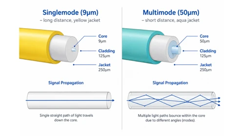
There is a popular intuition that fiber optic cable is "glass, therefore brittle." That intuition is half right. The glass core inside the cable really is brittle on its own - but that core is 125 microns wide, less than twice the diameter of a human hair. At that scale, glass behaves more like a textile fiber than a window pane.
Three engineering tricks combine to make the finished cable flexible:
2.1 Glass Is Stronger Than Steel - When Pulled Straight
This is counter-intuitive but well documented. Pulled axially, optical fiber has a tensile strength comparable to high-grade steel; modern fiber cables routinely specify maximum installation pull tensions of 200–600 lbf (890–2 700 N), versus around 25 lbf (110 N) for typical Cat-rated copper. The flexibility is bought by avoiding bending and crushing - not by softening the glass.
2.2 The Three Things That Actually Make Cable Flexible
Aramid Yarn (Kevlar) Strength Members
Almost every modern fiber cable contains aramid yarn (DuPont Kevlar® or equivalent) wrapped around the fiber. Aramid is light, it does not stretch under load, and it is extremely flexible. It absorbs the pulling force during installation so the glass core never sees a tensile load above its design limit.
Loose-Tube vs Tight-Buffered Construction
In a loose-tube cable, the 250 µm coated fiber sits inside a 2–3 mm gel-filled buffer tube with several millimeters of clearance. The fiber can shift inside the tube, which means small bends in the outer cable do not translate into stress on the glass. Tight-buffered designs trade some of this flexibility for crush resistance, which is why tight-buffered cables dominate indoor riser and breakout applications while loose-tube dominates outside plant.
Bend-Insensitive Glass (ITU-T G.657)
The third - and most significant - flexibility gain of the past 15 years is bend-insensitive single-mode fiber, standardized by the ITU under ITU-T G.657 (latest revision 08/2024). G.657 fibers add an engineered low-index trench (or a ring of microscopic air holes in some B3 designs) around the core that re-confines light that would otherwise leak out at a bend. The result: G.657.B3 fiber tolerates a 5 mm bend radius with around 0.15 dB/turn loss at 1550 nm - substantially better than the legacy G.652.D fiber that can exceed 0.5 dB/turn at 30 mm.
3. The Two Numbers Everyone Asks About: Bend Radius & Tensile Load
If you remember nothing else, remember these two numbers. Almost every "how flexible is fiber optic cable?" question ultimately reduces to one of them.
3.1 Bend Radius - The 10× / 20× Rule
Bend radius is the smallest curve the cable can take without optical or mechanical damage. The industry has standardized on two values per cable:
- Dynamic (under-tension, short-term) bend radius - used while pulling cable. Industry norm: 20× the outer diameter (D).
- Static (post-installation, long-term) bend radius - used once the cable is at rest. Industry norm: 10× D.
Concretely, a 3 mm patch cord wants 60 mm radius (~the diameter of a tennis ball) during install and 30 mm radius (~a coffee cup) long-term. A 10 mm OSP loose-tube cable wants 200 mm during install and 100 mm long-term.
Some standards use slightly different multipliers - ANSI/TIA-568 sets premises fiber static bend at 10× D, while ISO/IEC 11801 permits smaller radii under certain riser and horizontal channel conditions. In all cases, the cable manufacturer's datasheet takes precedence; it factors in the specific construction and has been validated against that product's test data.
3.2 Tensile Load - Why Patch Cords Fail at 60 N but OSP Cable Survives 2 700 N
Tensile load is how hard you can pull the cable before something stretches or breaks. Like bend radius, it has a short-term and long-term value. Typical numbers:
- Indoor LC/SC patch cord: 60–150 N installation, ~50 N residual.
- MTP/MPO trunk cable: ~240 N installation.
- Indoor distribution / riser: 600–1 800 N installation, ~600 N static.
- Outdoor loose-tube OSP: up to 2 700 N installation, ~600 N static.
- Aluminum-armored direct-burial: 800 N to several kN.
There are two consequences for installers:
- Never pull on the jacket. The aramid strength members are what take the load - pulling the jacket stretches it, which displaces the fibers inside and damages connectors at the far end.
- Use a swivel and a tension gauge. 100 N is roughly 22 lbf - a single technician can easily exceed this by hand on a 50 m run with friction.
Cable-Type Bend & Tensile Reference Table (Glory Test Data, 2026 Q1)
| Glory Cable Type | Outer Dia (mm) | Min Bend Radius (Static) | Max Tensile (Install) | Fiber Spec |
|---|---|---|---|---|
| LC/SC Patch Cord 2.0 mm | 2.0 | 20 mm (10×D) | 100 N | G.657.A2 |
| Drop Core Fiber Optic (Flat 2×3 mm) | 2.0 × 3.0 | 15 mm (B3 fiber, static) | 400 N | G.657.B3 |
| ROC DROP CABLE (Round Drop) | 4.8 | 48 mm | 600 N | G.657.A2 |
| GJFJV Indoor Riser 12-fiber | 8.0 | 80 mm | 1 200 N | G.657.A1 |
| Outdoor Loose-Tube 24-fiber | 11.0 | 110 mm | 2 700 N | G.652.D / G.657.A1 |
4. Bend-Insensitive Fiber: How G.657 Changes the Game
Until 2006, all standard single-mode fiber was made to ITU-T G.652. It worked fine in a straight conduit but was unforgiving inside an apartment, where corners are sharp and cable trays do not exist. The ITU answered with G.657, a family of bend-insensitive fibers that let installers route fiber the way they already routed Cat6: around a door frame, behind a baseboard, into a wall plate.

4.1 G.657.A1 - The Quiet G.652.D Replacement
G.657.A1 is fully forward- and backward-compatible with G.652.D. It fusion-splices into existing networks with negligible additional loss - typically well under 0.1 dB per junction under normal fusion conditions - and tolerates a 10 mm static bend radius with under 0.1 dB/turn loss at 1550 nm. Most modern indoor riser and distribution cables - including Glory's GJFJV Indoor Optical Fiber Cable - now ship with G.657.A1 by default. For most new indoor FTTH work in 2026, A1 or A2 is the practical default; G.652.D remains appropriate only where bend radii can be reliably held above 30 mm throughout the route and cost is the primary constraint.
4.2 G.657.A2 - 7.5 mm Bend Radius for FTTH Drops
G.657.A2 holds the same mode-field-diameter family as G.652.D (so it splices cleanly to legacy ODNs with under 0.1 dB additional loss) but pushes the bend tolerance to a 7.5 mm radius with about 0.05 dB/turn at 1550 nm. This is the workhorse fiber for outdoor FTTH drops, including Glory's Drop Core Fiber Optic, Outdoor Drop Cable, and the pre-connectorized Sticklok™ drop cables used in FTTH rollouts across Southeast Asia and Latin America.
4.3 G.657.B3 - 5 mm, the Pen-Diameter Test
G.657.B3 is the extreme. Its mode-field diameter (~6.3 µm vs 9.2 µm for G.652.D) means fusion-spliced junctions to legacy fiber incur 0.1–0.3 dB of mismatch loss per junction - manageable on a short access run with few splices, but it accumulates across multi-splice routes. In backbone or long-haul contexts, B3's slightly different chromatic dispersion profile also warrants attention, though at FTTH access lengths this is rarely the limiting factor. Despite these constraints, B3 tolerates a 5 mm bend radius - that is the diameter of a typical ballpoint pen barrel. B3 is reserved for indoor wiring inside MDU risers, customer-premises equipment patches, and dense data center cassettes where conventional fiber would not survive routing. It is also the fiber of choice for FTTR invisible indoor cables that must round 90-degree doorframe corners.
Macrobending Loss Curves (dB/turn) - Per ITU-T G.657 (08/2024)
| Fiber Grade | Min Bend Radius (Static) | Loss @ 1550 nm | Loss @ 1625 nm | Splice with G.652 | Typical Use |
|---|---|---|---|---|---|
| G.652.D (legacy) | 30 mm | 0.5 dB/turn | 1.0 dB/turn | Baseline | Long-haul, OSP trunk |
| G.657.A1 | 10 mm | ≤ 0.1 dB/turn | ≤ 0.2 dB/turn | Full (< 0.1 dB) | Indoor riser, data center |
| G.657.A2 / B2 | 7.5 mm | ≤ 0.05 dB/turn | ≤ 0.1 dB/turn | Full (A2) / Limited (B2) | FTTH drop, MDU in-building |
| G.657.B3 | 5 mm | ≤ 0.15 dB/turn | ≤ 0.45 dB/turn | System-level only | CPE patch, dense racks, FTTR invisible cable |
5. What Actually Breaks Fiber: Macrobend, Microbend, Kink, Crush
"Damage from bending" is actually four different failure modes, each with a different signature on an OTDR and a different prognosis. Confusing them is the most common mistake junior installers make.
5.1 Macrobend - Visible to the Eye (and to the OTDR)
A macrobend is any bend tighter than the cable's specified minimum. You can usually see it - it looks like a too-sharp corner, sometimes a coil that has been crushed flat. The OTDR signature is a step loss at the bend point that recovers fully if you straighten the cable. Macrobends are usually reversible if caught early; the cable can sometimes be re-routed and the loss disappears.
5.2 Microbend - Invisible Killers from Cable Ties and J-Hooks
Microbends are sub-millimeter undulations of the fiber inside the cable, caused by lateral pressure points: a too-tight nylon zip tie, a J-hook with a sharp edge, a bridle ring that concentrates the cable's own weight on a 5 mm contact patch. You cannot see microbends from the outside. The OTDR signature is small step losses scattered along the cable, often at the supports. Microbends usually do not recover, because the lateral pressure has compressed the buffer tube permanently.
Most fiber cable installation guides - and the IEC 61754 series connector and cable standards documentation - recommend hook-and-loop fasteners over cable ties for fiber runs, and dedicated fiber pathways over shared cable trays with copper.
5.3 Kink - The Permanent Damage Mode
A kink is a sharp fold - the cable doubled over on itself or pulled through a too-tight pulley. The glass core cracks at the kink point. The OTDR signature is a sharp loss event with a reflective spike. Kinked fiber is permanently damaged; even if it passes optically today, microscopic stress fractures will propagate and the link will fail within months.
If you find a kink, the only correct field action is to cut the cable on either side of the kink and splice. That a kinked fiber "still works" immediately after installation is entirely consistent with the failure pattern - and dangerous for exactly that reason. Stress fractures initiate at the kink and propagate under the residual tension in the installed fiber; the link may pass an OTDR sweep on day one and fail within months.
5.4 Crush - Why a Kicked or Pinched Cable May Die Six Months Later
Crush damage happens when the cable is laterally compressed beyond its rated load. Telcordia GR-20-CORE specifies minimum crush strength at 1 500 lbs/ft (21.9 kN/m) for outdoor cables; field practice typically targets sidewall tension at 50% or less of that limit during duct pulls. Published crush test data from industry sources suggests mechanical damage can initiate around 200 lbf when cable is pulled laterally across a narrow surface or sheave edge.
Visible signs: flattening of the jacket, an oval cross-section where it should be round. The cable may pass an OTDR test the day of installation but show creeping attenuation over weeks as the buffer materials cold-flow under sustained pressure. This is why a cable that was kicked, stepped on, or had a heavy box stacked on it during construction should be retested at 6 months.
6. Real-World Flexibility: What This Means in Your Home or Job Site
Numbers and standards are great for procurement; what most readers actually want is permission. Can I do the thing I am about to do? Here are the four scenarios that come up weekly in our support inbox.
6.1 Around a Door Frame, Behind Furniture, Under a Rug
With a G.657.A2 or B3 indoor patch cable, routing around a door frame, behind furniture, and - carefully - under a rug is generally within spec. A2 handles a 7.5 mm corner without measurable loss; B3 goes to 5 mm. "Under a rug" is technically a crush risk if heavy furniture rolls over the spot repeatedly; route along the wall edge rather than across open floor. Behind furniture is fine if there is no sustained pressure point. Around a door frame is fine provided the door cannot close on the cable.
6.2 In a Conduit That Already Has Power Cables
Avoid sharing conduit with power cables where possible. Power cables are heavier, stiffer, and run hotter; over time they tend to rest on lighter fiber cables and create microbends. Where co-routing is unavoidable, run the fiber inside a corrugated innerduct so it has its own independent pathway. NEC and most regional electrical codes already require physical separation of low-voltage from line-voltage wiring in many wall types - verify applicable code requirements before installation.
6.3 Coiling and Storing Slack
Always coil fiber in figure-8 patterns, never circles. A figure-8 puts a half-twist in on one loop and removes it on the next, so the cable does not develop torsional stress. Store coils with a diameter at least 20× the cable OD - for a 3 mm patch cord, that is a 60 mm coil minimum. Smaller coils are fine for transient handling but kill long-term reliability.
6.4 Cold-Weather Outdoor Conduit (the PPC Trap)
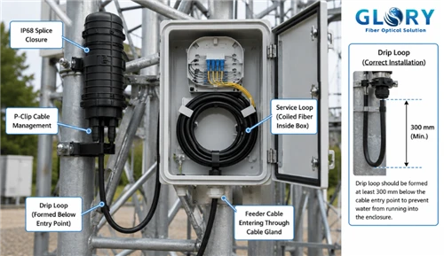
Water in an outdoor conduit freezes, expands, and can crush the cable inside. Climate-zone-appropriate cable design uses microducts (which limit how much water can collect) or a gel-filled jacket (which displaces water). For Russian, Canadian, Nordic, and high-altitude deployments, specify a microduct + air-blown installation rather than direct duct-pull. Glory's IP68-rated drop solutions are tested per IEC 60068-2-1 cold soak at −40 °C.
7. How to Tell If Your Fiber Was Already Damaged from Bending
Three layers of inspection, in order.
7.1 Visual Inspection Checklist
- Jacket flattening or oval cross-section → suspected crush damage.
- Sharp corners < cable's rated bend radius → macrobend.
- Folds, creases, or visibly white-stressed jacket → kink.
- Tight zip tie marks deeper than 0.5 mm into the jacket → microbend risk; replace ties with Velcro and re-test.
7.2 OTDR Signature Map (Macrobend vs Microbend vs Kink vs Crush)
| Failure Mode | OTDR Signature | Reflectance Spike? | Recoverable by Re-routing? |
|---|---|---|---|
| Macrobend | Single step loss at bend point | No (non-reflective) | Usually yes |
| Microbend | Multiple small step losses along cable | No | Sometimes - replace ties / supports |
| Kink | Sharp loss event with reflection | Yes | No - cut and splice |
| Crush | Slow attenuation creep over time | Variable | No - replace section |
7.3 The 6-Month Rule: Why You Test Twice
If construction or remodel work happened anywhere near the cable run, test once at hand-off and again at 6 months. Crush damage and microbend creep both follow viscoelastic timescales - they often do not show up on day 1 but become measurable by week 12. Re-testing catches the slow-developing failures before they cause a customer-visible outage.
8. Choosing the Right Cable: Flexibility-Driven Buying Checklist
Flexibility is not a single spec - it is a four-axis decision.
8.1 Indoor Patch Cord vs Drop Cable vs Riser vs Outdoor OSP
- Indoor LC/SC patch cord (1.6–3.0 mm OD) - most flexible, smallest bend radius (15–30 mm static), but lowest tensile (60–150 N). Use only where there is no pulling force and minimal mechanical risk. Glory's Fiber Patch Cord SKUs ship with G.657.A2 by default.
- FTTH drop cable (flat 2×3 mm or round 4.8 mm) - designed for the last 50 m to the home. Tensile 400–600 N, bend radius 15–48 mm, bend-insensitive G.657.A2/B3. See our FTTH Cable pages for spec sheets.
- Indoor riser / distribution (5–10 mm OD) - built for vertical runs through floors. Bend radius 50–100 mm, tensile up to 1 800 N, LSZH jacket for fire code.
- Outdoor loose-tube OSP (10–13 mm OD) - least flexible, but rated 2 700 N tensile, IP68, and −40 to +70 °C operating. Use anywhere the cable will see weather, animals, or buried duct.
8.2 When to Specify G.657.A2 vs B3
Default to G.657.A2 unless your installation has explicitly tight bends. A2 is fully spliceable to legacy G.652.D networks with negligible additional splice loss (typically < 0.1 dB per junction), costs about 8–12% more than G.652.D, and tolerates 7.5 mm bends - enough for almost every real-world MDU and FTTH drop scenario.
Specify G.657.B3 only when you have a 5 mm or tighter routing constraint that B3 will solve and a bend-loss budget that can absorb a slightly higher per-bend loss. Common B3 use cases: dense data center cassette internals, customer-premises equipment patches with right-angle wall plates, robotics with continuous flex, and FTTR invisible indoor cables at 90-degree doorframe corners.
9. Frequently Asked Questions
The practical questions that come up most often during specification, installation, and field troubleshooting.
- Is fiber optic cable flexible?
- Yes - modern fiber cables are designed to be flexible, but only within specified limits. The aramid yarn, loose-tube construction, and bend-insensitive glass (ITU-T G.657) all work together to allow tight routing. Standard cables tolerate a 30 mm bend radius; bend-insensitive G.657.B3 tolerates 5 mm.
- How much can you bend a fiber optic cable?
- During installation: 20× the cable's outer diameter. After installation: 10× the outer diameter. For a typical 3 mm patch cord that is 60 mm during pull, 30 mm at rest. Bend-insensitive G.657 fibers reduce these to 10 mm (A1), 7.5 mm (A2), or 5 mm (B3).
- Is fiber optic cable more fragile than copper?
- Counter-intuitively, no - pulled axially, fiber tensile strength is 200–600 lbs (890–2 700 N) versus 25 lbs (110 N) for copper. But fiber fails brittlely at sharp bends or kinks, while copper deforms plastically. Copper is more forgiving of abuse; fiber is stronger but less tolerant.
- Can a kinked fiber optic cable be repaired?
- No - a kinked fiber is permanently damaged at the kink point. The correct field repair is to cut the cable on either side of the kink and re-splice with a fusion or mechanical splice.
- How do I install fiber optic cable around corners?
- Maintain at least the rated bend radius (10× OD long-term). Use sweeping bends, not sharp turns. For tight corners, specify G.657.A2 or B3 fiber. In a conduit, use sweeping 90° elbows rather than mitered corners.
- Is fiber optic cable safe to step on?
- Once is usually survivable; repeatedly is not. A single foot pressure may not exceed crush rating, but the damage is cumulative. Microbends and jacket flattening from foot traffic show up as creeping attenuation weeks later. Route fiber where it cannot be stepped on, or use armored cable in those areas.
The sections below provide the full reference tables, optical loss budget mathematics, OTDR diagnostic framework, and fiber selection matrix that the preceding summary draws from. Engineers working through a specific design problem can jump directly to the relevant section using the table of contents above.
G.652 vs G.657: Quick Comparison
| Item | G.652.D | G.657.A2 |
|---|---|---|
| Min Bend Radius (Static) | 30 mm | 7.5 mm |
| FTTH Drop Use | Limited | Recommended |
| G.652.D Splice Compatibility | Native | Full (< 0.1 dB) |
Read our complete G.652 vs G.657 comparison guide →
Bend Radius and Loss Budget
Every bend adds insertion loss. A 50 m residential drop with 8 right-angle corners shows why fiber grade selection matters - the numbers below use a 28 dB GPON Class B+ budget.
| Loss Component | G.652.D (30 mm) | G.657.A2 (7.5 mm) | G.657.B3 (5 mm) |
|---|---|---|---|
| Feeder + distribution fiber (5.5 km × 0.35 dB/km) | 1.93 dB | 1.93 dB | 1.93 dB |
| 1:32 PLC splitter | 17.5 dB | 17.5 dB | 17.5 dB |
| Connectors (2 × 0.5 dB) | 1.00 dB | 1.00 dB | 1.00 dB |
| Splices (2 × 0.10 dB) | 0.20 dB | 0.20 dB | 0.20 dB |
| 50 m drop fiber (linear) | 0.02 dB | 0.02 dB | 0.01 dB |
| 8 right-angle bends (per-turn × 8) | 4.00 dB (8 × 0.5) | 0.40 dB (8 × 0.05) | 1.20 dB (8 × 0.15) |
| Total plant loss | 24.65 dB | 21.05 dB | 21.85 dB |
| Headroom vs 28 dB budget | 3.35 dB (marginal) | 6.95 dB (comfortable) | 6.15 dB (comfortable) |
G.652.D's 3.35 dB headroom is a lab number - real-world connectors, mechanical splices, and contamination can easily consume it. A G.652.D drop with 8 corners goes link-dead on a bad day. G.657.A2 absorbs all those variables and still has 4+ dB to spare - which is why major FTTH operators standardize on G.657.A2 for the subscriber access drop.

Fig. 2 - Macrobend loss curves at 1550 nm for G.652.D and G.657 grades. G.652.D deteriorates rapidly below 30 mm, making indoor routing impractical. G.657.A2 and B3 maintain acceptable loss at their minimum radii. Source: Glory Optical factory data (2026 Q1, n=240/grade) plotted against ITU-T G.657 (08/2024) upper-bound limits.
Fiber Optic Bend Radius: Engineering Diagrams for the Field
The four diagrams below cover the most common engineering scenarios - what "static vs dynamic" looks like at human scale, how to route cable correctly at corners and conduit entries, and the OTDR signatures that separate the recoverable from the irreparable. Print them, pin them in the van, or include them in site-supervisor briefing packs.
 vs static (installed) bend radius at human scale.")
Fig. 3 - Dynamic (installation) vs static (installed) bend radius at human scale. The key insight: G.652.D's 30 mm static limit is approximately a coffee-cup diameter - a tight baseboard corner violates it. G.657.A2's 7.5 mm limit is a USB-port-width, and G.657.B3's 5 mm is a pen-barrel. Source: Glory Optical engineering illustration.

Fig. 4 - Ten cable routing scenarios: correct vs incorrect installation practices. The most common field failures are zero-cost to prevent - specify G.657.A2 for all indoor drops, use hook-and-loop ties, and never route fiber across a walking path without armor. Source: Glory Optical engineering illustration.
Product Recommendations: Match the Cable to Your Bend Requirement
Correct fiber grade selection removes the most common source of FTTH access-layer failures before they happen. The matrix below maps bend-radius requirements to specific cable lines, all G.657-grade and factory-tested with per-batch OTDR, insertion loss, and return loss certificates from ISO 9001:2015-certified production.
FTTH Drop Core & ROC Drop Cable
The workhorse for outdoor last-drop and MDU entry runs. Flat 2×3 mm or round 4.8 mm OD, 400–600 N tensile, UV-stable jacket, self-support and figure-8 configurations available. Pre-terminated SC/APC or factory-bare for field connectorization. Batch-tested at 1310 nm and 1550 nm with full IL/RL report.
View FTTH Cable LineIndoor Fiber Optic Cables - Riser & Distribution
GJFJV tight-buffered riser, GJBFJV breakout for per-fiber pulls, and ultra-slim mini-bundled cable for MDU in-building distribution. LSZH jacket, 0.9–8 mm OD, 1–24 fibers. G.657.A1 as default; A2 upgrade on request. Suitable for vertical shafts, horizontal cable trays, and behind-drywall runs.
View Indoor CablesUltra-Slim Indoor Drop & Invisible FTTR Cable
0.9–1.6 mm OD transparent-jacket single-fiber drop cable for FTTR and in-room routing. G.657.B3 fiber survives 90° doorframe and baseboard corners without measurable loss. Self-adhesive or guide-rail compatible. Pre-terminated SC/APC both ends for tool-free field install. The cable that makes FTTR invisible.
View Ultra-Slim CableOutdoor Drop & OSP Cable
Gel-filled loose-tube OSP cable for aerial, duct, and direct-burial last-mile runs. IP68-rated, −40 to +70 °C operating range, 2 700 N installation tensile. UV-resistant PE jacket. Available in G.657.A2 (drops) and G.652.D/A1 (trunk). IEC 60068-2-1 cold-soak tested. Armor options: dielectric, flat steel, corrugated steel.
View Outdoor Cable
Fiber Patch Cords & Pigtails
SC/APC, LC/APC, SC/UPC, LC/UPC, and MU in simplex and duplex. 2.0 mm and 1.6 mm OD, G.657.A2 standard, 60–150 N tensile. IEC 61300-3-35 (insertion loss) and IEC 61300-3-6 (return loss) per-batch factory tested. LSZH jacket for riser-rated environments. Low-loss APC end-face: ≤ 0.2 dB IL, ≥ 65 dB RL.
View Patch Cords
SC/APC Fiber Quick Connector (Fast Connector)
Tool-light mechanical field connector for drop cable termination and on-site repairs. Pre-polished ferrule, 60-second assembly, no epoxy or polishing required. < 0.5 dB insertion loss, > 40 dB return loss typical. Compatible with G.657.A2 and B3 cable at the rated bend radius - the correct field-repair answer when you cut out a kinked section.
View Fast ConnectorNeed a custom cable grade, jacket color, outer diameter, or pre-terminated assembly for a private-label rollout? Glory Optical's OEM/ODM program covers custom invisible-cable assemblies, pre-connectorized FTTR drop kits, and branded packaging with per-batch test documentation. Lead times from 15 working days for prototypes; full production from 45 days depending on volume. Learn about OEM / ODM services →
Article authored by the Glory Optical engineering team. Ningbo Glory Optical Communication Co., Ltd. - ISO 9001:2015-certified fiber optic component manufacturer and ODN solution provider since 2008, operating from a 20,000 m² facility and supplying telecom operators, data center operators, and ISPs in 50+ countries across the Americas, Europe, Africa, the Middle East, and Southeast Asia. All bend radius, tensile, and macrobend loss figures in this article are derived from Glory factory test data (2026 Q1) and ITU-T G.657 (08/2024) published limits. Contact our engineering team for loss budget design, ODN optimization, and OEM/ODM cable assembly.
Request a quote · Contact the technical team · OEM / ODM services · About Glory Optical
Standards referenced: ITU-T G.652.D (2016); ITU-T G.657 (08/2024, all categories A1, A2, B2, B3); IEC 61300-3-1 (macrobend attenuation measurement); IEC 61280-4-1 (installed cable plant OTDR testing); ANSI/TIA-568 (premises fiber installation); ISO/IEC 11801 (generic cabling); Telcordia GR-20-CORE (OSP cable crush); IEC 60068-2-1 (cold-soak operational test); IEC 61754 (fiber optic connector interfaces). Bend-loss values are upper-bound limits per ITU-T G.657 (08/2024) test conditions (1 turn, stated bend radius, 1550 nm and 1625 nm) unless stated otherwise. Glory factory test data is from Q1 2026 production batches; n-values are noted where cited. All figures should be verified against current cable datasheets before design or procurement. Prices and cost premiums are market approximations and vary by volume, region, and supplier.