A frozen fiber splice closure is first a water-ingress failure and then a mechanical and optical fault. The immediate task is to locate the affected fibers without disturbing the evidence, gain controlled access, determine what must be repaired or replaced, restore the complete sealing boundary and verify the finished link.
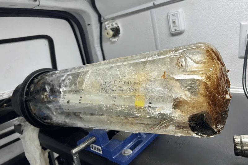
Confined freezing can create crushing forces and contribute to macrobending, microbending, added loss and fiber breakage. However, the exact tray-level failure pattern cannot be predicted from the amount of visible ice alone. Treat local pressure points, tray displacement and selective fiber damage as possible mechanisms to be confirmed by site records, inspection and testing.
What Can Freezing Water Do Inside a Fiber Splice Closure?
ITU-T L.102 documents the general cable mechanism: water that freezes under confined conditions can crush fibers, produce macrobending and microbending, increase optical loss and possibly break fibers. It also notes that water migrating toward closures can affect fibers and splices.
That source supports the broad freeze-damage mechanism, but it does not establish one universal failure pattern inside every dome closure. Water level, free volume, tray construction, fiber routing and cable fixation vary. Claims about which tray edge or splice protector moved in a specific enclosure remain engineering hypotheses until confirmed.
| Observed Result | Possible Mechanism | Evidence Needed |
|---|---|---|
| Loss changes during thawing | Temporary pressure may have reduced the bend radius without breaking the glass. | Time-stamped power readings or OTDR traces before, during and after controlled thawing |
| One fiber remains open after thawing | A permanent crack or break may exist at a tray edge, tube exit, splice transition or another stressed point. | OTDR event location, visual inspection and continuity testing |
| Some circuits work while others fail | The affected fibers may occupy different positions or have different available slack and optical margin. | Fiber map, tray position, baseline loss and affected-fiber pattern |
| High loss or reflectance in a connectorized closure | Contamination, a damaged adapter or disturbed connector contact may be involved. This does not apply to fusion-splice-only closures. | Connector inspection, cleaning record, reflectance result and component inspection |
For closure qualification, ITU-T L.201 covers mechanical integrity and optical stability under environmental and maintenance-related tests. Its non-normative Ukrainian-experience appendix includes separate water-penetration and freeze-thaw procedures. Those appendix conditions are useful references, not proof that an untested model or cable-port configuration passed them.
How Did Water Reach the Sealed Volume?
The repair will repeat if the investigation stops at the first wet gasket. Glory Optical's guide to fiber cable waterproofing and longitudinal water migration explains why the cable, cable entry, closure seal and connected duct system must be reviewed together.
| Potential Path or Contributor | What to Check | Repair Boundary |
|---|---|---|
| Dome-to-base seal after re-entry | Gasket condition, groove contamination, lubricant, collar or clamp engagement and permitted seal reuse | Follow the exact model's re-entry and resealing procedure |
| Cable-to-port interface | Measured cable OD, roundness, sheath damage, grommet or heat-shrink kit, unused-port plugs and compression sequence | Match each cable construction to its specified entry kit |
| Microduct or duct termination | Couplers, gas/water blocks, end plugs, empty ducts, route slope and upstream low points | Inspect upstream when the duct terminates inside or communicates with the closure |
| Remote sheath or tether damage | Cuts, animal damage, impact cracks, loose hardened interfaces and evidence of longitudinal migration | Repair the original entry point, not only the lowest wet component |
| Mounting and cable strain | Bracket condition, entry orientation, slack-coil tension and axial or side load on the port | This is usually a contributor to seal failure rather than a separate water path |
Step 1: Diagnose Before Moving or Opening the Closure
Preserve the original condition long enough to separate the closure fault from an unrelated splice, launch cable or test-set problem.
- Identify affected circuits, wavelengths and service symptoms.
- Retrieve baseline power readings, acceptance traces and the fiber-to-tray map.
- Verify the test leads and connectors before interpreting a changing OTDR result.
- Photograph the mounting position, ice or water level, cable entries, bracket, visible damage and route direction.
- Record the technician, time, air temperature, closure model and seal or port configuration.
- Support the enclosure before releasing straps or hardware; trapped water and ice may add unexpected weight.
Use the same test setup and wavelengths when comparing results wherever operational conditions permit. Glory Optical's guide to unstable OTDR results and test-path errors explains why a damaged launch cable or connector can imitate a field event.
Step 2: Support and Thaw the Closure Under Controlled Conditions
The objective is access without adding thermal or handling damage. There is no universal thawing temperature or heat-source procedure for every dome, seal and buffer-tube system.
- Use the network owner's approved method and the closure manufacturer's instructions.
- Keep the enclosure supported and collect meltwater so its path can be observed.
- Avoid uncontrolled concentrated heat on the housing, gaskets, buffer tubes, fibers and adapters.
- Do not treat heat-shrink installation instructions as an automatic thawing procedure.
- Do not pull trays or frozen fiber loops free. Wait until components can move without resistance.
If loss changes during thawing, preserve the time-stamped readings. That before-and-after record is more useful than describing the event later from memory.
Step 3: Decide What to Repair or Replace
Make the decision component by component after the ice has cleared and the original routing has been documented.
| Component | Reuse or Repair Only When | Replace or Rework When |
|---|---|---|
| Dome, base and clamp | No crack, permanent distortion, damaged sealing surface or insecure locking feature is found. | The housing is cracked or warped, the sealing land is damaged, or the clamp cannot restore uniform engagement. |
| Gasket or entry-seal kit | The exact manufacturer procedure permits reuse and the component remains clean, undamaged and dimensionally stable. | The re-entry procedure requires replacement, or the seal is cut, stretched, contaminated, hardened or incorrectly sized. |
| Splice tray and sleeve holders | The tray retains its shape, cover, hinges and holders and permits compliant fiber routing. | The tray is cracked or distorted, holders no longer retain sleeves, or covers and hinges load the fibers. |
| Fiber and fusion splice | The coating and glass show no damage, routing can be restored and the finished circuit meets the required optical acceptance criteria. | A fiber is broken or cracked, a splice protector or bare-fiber region is damaged, or loss remains unacceptable or unstable. |
| Adapters and connectors, if present | Inspection and cleaning restore an acceptable end face and the component passes the required loss and reflectance checks. | The ferrule, adapter, latch, sealing feature or mating geometry is damaged. Inspect connector end faces using the applicable IEC 61300-3-35:2022 criteria. |
| Cable fixation and strength-member hardware | The cable remains fixed without placing axial or side load on the entry seal. | Clamps, brackets or strength-member fixtures are loose, corroded, cracked or incompatible with the cable. |
Where resplicing is required, follow a controlled strip, clean, cleave, splice, protect, route and test process. The broader sequence is covered in Glory Optical's fusion-splicing field guide.
Step 4: Restore the Complete Sealing Boundary
Trace the route from the flooded volume outward. Replacing the main gasket is sufficient only when the investigation has established that it was the complete entry path.
- Clean and inspect the dome-to-base sealing surfaces.
- Replace or restore seals according to the exact product instructions.
- Match every cable to its approved grommet or heat-shrink kit.
- Seal unused ports and microducts with the specified components.
- Fix the cable and strength member so they do not load the seal.
- Check the upstream microduct, tether and cable sheath for remote damage.
- Restore the approved mounting orientation and support hardware.
Step 5: Complete Sealing and Optical Acceptance
Perform the Model-Specific Sealing Check
Flash-test pressure and method are product-specific. The official PLP COYOTE dome procedure and Corning 2178 procedure each specify pressure and resealing steps for their own models. Use the instructions for the repaired closure; do not transfer a pressure value or seal treatment from another design.
Verify Link Loss and Individual Events
End-to-end insertion-loss testing and OTDR testing answer different questions. The Fiber Optic Association's OTDR guidance explains that an optical loss test verifies the link as used, while an OTDR locates and characterizes splice, bend and reflection events. Compare results with the project loss budget, the required wavelengths and the original acceptance records.
- Repeat the required insertion-loss or optical-power tests after final routing.
- Repeat OTDR testing with verified launch and receive cables where the project requires event-level acceptance.
- Retain trace files rather than screenshots alone.
- Record replaced components, seal-kit part or lot, cable OD, port position and sealing-test result.
- Attach before-opening and after-routing photographs to the same repair record.
How to Reduce the Risk of Another Freeze Failure
For replacement projects, request evidence for the supplied assembly rather than relying on an enclosure-level IP label.
| Requirement | Evidence to Retain |
|---|---|
| Water-ingress and freeze-thaw performance | Test method, edition, temperature range, cycles, sample configuration and acceptance result |
| Cable and port compatibility | Measured cable OD, grommet or heat-shrink kit, port map and tested cable construction |
| Re-entry performance | Permitted re-entry cycles, replacement-seal rule and repeat sealing result |
| Installation limitations | Minimum installation temperature, mounting method, cable-load limits and approved sealing check |
Telcordia GR-771 and ITU-T L.201 can anchor a closure specification, but the RFQ should identify the required issue, application and test conditions. A report for another size, port kit or cable configuration is not automatically evidence for the ordered BOM.
Glory Dome Closure Options
The choice between heat-shrink and mechanical sealing should follow the network's cable plan and expected re-entry frequency. Both architectures can protect outdoor splices when the correct entry components, cable fixation and installation procedure are used.


Match the Closure to the Repair and Re-entry Plan
Send the installation environment, cable construction and OD, port map, splice count, mounting method, re-entry plan and required environmental evidence for configuration review.
Request a Quote View Fiber EnclosuresFrequently Asked Questions
Q: Can freezing water inside a fiber splice closure break the fibers?
A: Yes. ITU-T cable guidance documents that confined freezing water can create crushing forces, macrobending, microbending, added optical loss and possible fiber breakage. Inside a closure, the exact tray-level result depends on the water level, routing and available space, so the affected component must be confirmed by inspection and optical testing.
Q: Why can a frozen fiber closure continue carrying traffic?
A: The frozen water may not load every tray or fiber in the same way, and a link with adequate optical margin may remain operational despite added bend loss. Continued service is useful diagnostic evidence, but the closure still requires inspection, sealing repair and acceptance testing.
Q: Can a heat gun be used to thaw a frozen splice closure?
A: Do not apply uncontrolled concentrated heat. A heat source can damage buffer tubes, seals or the housing, and heat-shrink installation instructions are not automatically a thawing procedure. Use the network owner's approved method and the closure manufacturer's instructions.
Q: How should a repaired fiber splice closure be tested?
A: Perform the model-specific sealing check, then complete the optical tests required by the network owner. End-to-end insertion-loss testing verifies the repaired link against its loss budget, while OTDR testing locates and characterizes splice, bend and reflection events. Retain the final readings and trace files with the repair record.
Conclusion
Repair a frozen fiber splice closure as a complete failure chain: preserve the original evidence, gain controlled access, confirm the damaged components, remove the full water path, rebuild the sealing system and verify both link loss and individual optical events. The mechanisms described here are conditional engineering scenarios rather than statistical failure-rate evidence; final acceptance remains model- and project-specific.