Where optical splitters are used, which format fits each location, and the one engineering risk that should be checked before installation.
Where are optical splitters used?
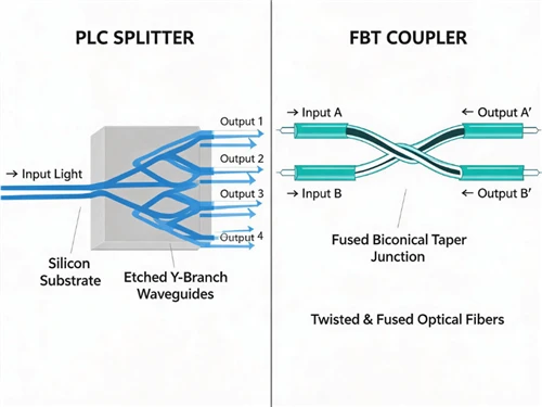
Optical splitters distribute or tap optical power in FTTH/PON, rural access networks, MDUs, passive optical LANs, CATV/RFoG, monitoring systems, and fiber sensing or laboratories. Choose by optical function first: equal fan-out usually points to a PLC splitter; an unequal tap or wavelength-limited application may need an FBT splitter or another passive component.
A splitter is passive but not lossless. Before choosing a part number, define the output pattern, worst-path loss allowance, installation enclosure and maintenance method. For a concise technology comparison, see FBT vs PLC splitter selection. If the function is wavelength separation rather than power division, specify a WDM device instead of calling it a splitter.
Seven Optical Splitter Application Scenarios
1. Centralized FTTH or FTTP PON
A centralized splitter places the full fan-out-often 1×16 or 1×32-in one accessible fiber distribution hub or cabinet. It suits dense service areas where technicians need simple port records, straightforward subscriber turn-up and one obvious test point. PLC technology is normally preferred because it supports high, uniform split counts across common PON wavelengths.
Field note: a larger split ratio saves OLT ports but leaves less optical margin and may strand more customers behind one failure point. Compare the real budget impact in 1×16 vs 1×32 PLC splitters, then match the module to a splitter distribution box.
2. Distributed or Cascaded Rural PON
A two-stage layout-such as 1×4 near the feeder and 1×8 closer to subscribers-can postpone ports and fiber capacity until demand appears. This is useful where homes are scattered, but each extra stage adds loss, enclosure exposure and another place to search during an outage.
Field note: do not approve a cascade from the nominal 1×4 + 1×8 ratio alone. Include both splitter maxima, both enclosures and every intermediate connector in the same path worksheet. Use the ODN design guide to place splitters in the complete feeder–distribution–drop route.
3. MDU and FTTB Distribution
In apartments and mixed-use buildings, splitters are commonly placed in a basement telecom room, floor distribution box or riser cabinet. The optical calculation may be easy; access control, bend radius, fire-stopping and a clean handoff to each unit often determine whether the installation remains serviceable.
Field note: assign a permanent building–floor–box–port identifier before splicing. Labels that only repeat the splitter output number become ambiguous as soon as several identical modules are installed in one riser.
4. Passive Optical LAN in Campuses, Hotels and Hospitals
Passive optical LAN uses PON architecture inside a property: an OLT feeds passive splitters, and ONTs serve rooms, floors or work areas. Splitters can reduce intermediate powered closets, but the design must still account for endpoint density, service availability, pathway diversity and moves/adds/changes.
Field note: map each critical service to the OLT port, splitter and ONT that support it. A visually diverse horizontal cable route is not resilient if both endpoints share the same upstream splitter.
5. CATV and RFoG Distribution
Broadcast optical video can be divided among multiple receivers, while RFoG uses passive distribution for downstream and upstream optical paths. Receiver power windows and reflections are critical: "some light is present" does not prove that carrier quality is acceptable.
Field note: test optical power at the receiver, then verify the service-level RF metric. A path can pass a basic optical-power check while reflections or upstream optical beating still impair the channel.
6. Optical Monitoring and Test Systems
A low-percentage tap can send a sample to a power meter, photodiode or analyzer while most optical power stays on the live path. Here the requirement is usually an unequal coupling ratio, not a standard 1×N access splitter. Directionality and wavelength behavior may matter as much as insertion loss.
Field note: define 90/10 from a named input port and identify the monitor branch on both drawing and housing. Otherwise a correct asymmetric component can be installed in the wrong orientation.
7. Fiber Sensing and Laboratory Instrumentation
Splitters route a source to several sensing branches, combine returns or create reference and measurement paths. Laboratory setups often reveal problems hidden in access-network specifications: polarization sensitivity, phase stability, connector repeatability and bidirectional performance.
Field note: record the connector cleaning state and launch conditions with baseline readings. Without that reference, connector repeatability can be mistaken for sensor drift or splitter instability.
Application-to-Splitter Decision Matrix
Use this matrix as a first-pass specification, not a substitute for the link design. The same product family can serve several markets, but placement and acceptance criteria change with the consequence of failure. Start in the application row, then validate the three universal checks below.
| Application | Likely choice | Placement/package | Decision driver |
|---|---|---|---|
| Centralized FTTH | 1×16 or 1×32 PLC | FDB; cassette, LGX or ABS | Worst-path loss and serviceability |
| Rural cascaded PON | Two PLC stages | Sealed closures/FDBs | Take rate versus added fault points |
| MDU/FTTB | 1×8 to 1×32 PLC | Riser, floor box or rack | Physical fit, labels and access |
| Passive optical LAN | PLC selected to endpoint count | Telecom room or zone box | Capacity and availability design |
| CATV/RFoG | PLC or unequal FBT | Node, cabinet or rack | Receiver window and reflectance |
| Monitoring/test | Unequal 1×2 FBT tap | Inline or instrument chassis | Tap tolerance and direction |
| Sensing/lab | PLC, FBT or specialty coupler | Bench or protected enclosure | Wavelength, PDL and stability |
Three Checks for Every Application
1. Check the Worst Optical Path
For an equal N-way split, ideal splitting loss is 10 log10(N) dB. A real splitter is higher because it also has excess loss. The comparison below uses typical published maxima from a Glory PLC splitter specification; confirm the exact package, connector and wavelength before design release.
| Equal split | Ideal loss | Example published maximum | Unallocated difference |
|---|---|---|---|
| 1×8 | 9.03 dB | 10.2 dB | 1.17 dB |
| 1×16 | 12.04 dB | 13.5 dB | 1.46 dB |
| 1×32 | 15.05 dB | 16.8 dB | 1.75 dB |
| 1×64 | 18.06 dB | 20.5 dB | 2.44 dB |
Add connector pairs, splices, fiber attenuation, repair allowance and engineering margin separately. The worst output-not the average-controls acceptance. This treatment is consistent with the component framework in ITU-T G.671.
2. Match the Package to the Worksite
Bare fiber, steel tube, ABS module, cassette and LGX formats may contain a similar optical circuit but create very different field outcomes. Confirm enclosure dimensions, pigtail length, connector type and polish, adapter count, bend radius, cable entry and technician access. Browse PLC splitter formats only after these site constraints are known.
3. Test the Evidence, Not Only the Label
Request per-port insertion loss at the required wavelengths, then review worst port, uniformity, return loss, PDL and directivity. The report should match the ordered ratio, package, connector polish and batch or serial identity; use this PLC splitter test-report guide. An ISO 9001 quality system supports process control, but it does not replace product-level optical results.
RFQ minimumState the application, topology, split ratio or coupling ratio, operating wavelengths, maximum insertion loss, return loss/PDL needs, package dimensions, fiber and pigtail length, connectors and polish, environmental range, labeling, quantity and required test records. The Fiber Broadband Association splitter architecture paper is a useful independent planning reference for access-network placement.
Optical Splitter Application FAQs
Where are optical splitters used most often?
FTTH and other PON access networks are the highest-volume application. Other uses include MDUs, passive optical LAN, CATV/RFoG, monitoring and sensing.
Does a fiber splitter reduce signal strength or internet speed?
It always reduces optical power. It does not divide data rate like an unmanaged electrical hub; service speed depends on the PON protocol and capacity plan. If received power falls outside the transceiver budget, reliability and service can fail.
Can optical splitters be cascaded?
Yes. Cascading can align capacity with geography or take rate, but all stages, connectors and splices must fit within the worst-path loss budget, and each stage must be traceable.
Are optical splitters used in data centers?
They can support passive optical LAN, monitoring and selected broadcast optical systems. They do not replace Ethernet switches or create independent point-to-point server links.
When should PLC be selected instead of FBT?
Choose PLC for uniform, higher-count fan-out and broad common PON wavelength coverage. Choose FBT when a low-count or unequal coupling ratio is the actual requirement. Validate the datasheet against the application rather than choosing by technology name alone.
Choose the Scenario Before the Splitter
The same 1×N label can describe very different field requirements. Centralized FTTH prioritizes uniformity and access; rural cascades prioritize topology records; MDUs prioritize physical fit; RFoG prioritizes receiver windows; monitoring prioritizes a controlled tap; and sensing may prioritize wavelength or polarization behavior. Start with the scenario, calculate the worst path, then freeze the package and acceptance data.
Need an Application-Based Configuration Review?
Send Glory Optics your topology, power budget, enclosure drawing and connector plan. The engineering team can review the splitter format and test requirements before quotation.
View Optical Splitters Send an Inquiry