
Introduction
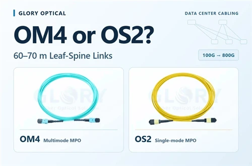
The decision comes down to three things: whether the complete OM4 channel can run the modules you already own, which installed components can carry the next generation, and what each path costs to build and upgrade.
Short answer
- Plan OS2 for the new 60–70 m fixed trunks if the 800G interface is undecided or pulling another trunk later would be disruptive.
- Use the existing 100G SR4 stock on suitable OM4 channels. A qualified 100G SR4 channel can reach 100 m on OM4. Confirm the installed channel length and loss, including the patch cords.
- Specify MPO or LC by the planned optic. At 400G, DR4 uses eight active fibres and supports compatible 4×100G breakout. FR4 uses one duplex pair for a 400G point-to-point link.
- What a 70 m OM4 channel uses
- What the SR4 stock carries forward
- Multimode reach at 60–70 m
- DR4 vs FR4: choosing the interface
- What you can reuse at 800G
- A link-by-link layout
- Compare first-order and upgrade costs
- Pre-purchase checklist
- FAQ
- Sources
What a 70 m OM4 channel uses
100GBASE-SR4 has a 100 m operating range and a maximum channel insertion loss of 1.9 dB on OM4. These are separate checks. If 70 m describes the trunk route, add the lengths of the equipment cords and any cross-connect jumpers before checking the distance. The loss limit applies to the defined channel. 100GBASE-SR4 application parameters.
For the example, an assumed cabled-fibre attenuation of 3.5 dB/km at 850 nm gives about 0.25 dB over 70 m. Compare the following layouts at the same total length. Their per-mate values are assumptions and should be replaced with the component specifications for the actual build.
| Passive MPO mates in the example | Assumed loss per mate | Estimated channel loss |
|---|---|---|
| 2 | 0.35 dB | ≈ 0.95 dB |
| 4 | 0.35 dB | ≈ 1.65 dB |
| 4 | 0.50 dB | ≈ 2.25 dB |
The last layout already exceeds 1.9 dB in the estimate. The four-mate, 0.35 dB layout leaves about 0.25 dB against that ceiling before any separately specified design margin. Use the project's connection and splice allowances and the selected module's requirements. Before turn-up, test insertion loss and polarity over the agreed passive endpoints. Fluke Networks MPO testing guide.
What the SR4 stock carries forward
Existing 100G SR4 modules can serve qualified OM4 links that will stay at 100G. If a new switch must connect to those modules, check the vendor's supported breakout combinations. Cisco's 400G SR4.2 example lists 100G SR1.2 as its 4×100G counterpart. Its separate 2×100G SR4 module supports two legacy 100G SR4 links. Verify the exact host, module and far-end part numbers. Cisco 400G optics and breakout examples.
Keep OM4 trunks and multimode assemblies with the links they serve. For a move to single-mode, replace the fibre assemblies in that channel. An existing enclosure or panel frame may be reusable if it accepts the correct adapter plate or cassette. Check the new module's MPO format, polish and pinning at every mating interface. For example, NVIDIA specifies MPO-12 APC on its cited 400G DR4 module. NVIDIA 400G DR4 specification.
Multimode reach at 60–70 m
At this distance, the optics class matters as much as the Ethernet rate. Check the reach of the full channel against the exact module selected.
| Application | OM4 reach | 60–70 m full channel |
|---|---|---|
| 100GBASE-SR4 | Up to 100 m | Within distance range. Check insertion loss. |
| 400GBASE-SR8 / 400GBASE-SR4.2 | Up to 100 m | Within distance range. Check the specific port, fibre count and breakout. |
| 400GBASE-VR4 / 800GBASE-VR8 | Up to 50 m | Outside the published range. |
| 800GBASE-SR8 | Up to 100 m | Within distance range. Check the 16-fibre path and the SR8 loss limit. |
IEEE 802.3df-2024 is the published reference for 800GBASE-SR8 and VR8. For an actual 60–70 m project, confirm that the proposed 800G SKU explicitly supports the required OM4 reach. For example, Cisco's OSFP-800G-VR8 lists up to 50 m on OM4. IEEE 802.3df-2024 · TIA FOTC multimode application table · Cisco 800G data sheet.
For planning beyond 800G, IEEE P802.3ds lists 30 m and 50 m multimode objectives at 200 Gb/s per wavelength, including 1.6 Tb/s. Its objectives apply to multimode fibre and do not specify that ordinary OM4 meets both distances. Task force material discusses a higher-bandwidth grade for the 50 m case. Use these objectives as a roadmap reference. IEEE P802.3ds objectives · IEEE task force material on 50 m reach.
DR4 vs FR4: choosing the interface
Settling on OS2 does not settle the interface. The two main 400G single-mode choices use different fibre counts, connectors and spares, and the choice follows from how you plan to use the links.
| 400GBASE-DR4 | 400GBASE-FR4 | |
|---|---|---|
| Fibres per link | 8 (4 pairs, MPO-12 with 4 unused) | 2 (one duplex pair) |
| Connector examples | MPO-12 APC (NVIDIA example) | Duplex LC (Cisco FR4 example) |
| Reach | 500 m | 2 km |
| Channel loss limit | 3.0 dB | 4.0 dB |
| Breakout to 4×100G | Yes, through an MPO-to-LC fanout | No; wavelength-multiplexed, point-to-point |
| Patch-panel impact | MPO adapters and trunks; LC cassettes where breaking out | LC adapters; fewer fibres per link |
What the choice depends on
- Do you need breakout? If leaf or spine ports will run as 4×100G toward existing 100G gear, DR4 is the interface built for it. For 400G point-to-point, FR4 uses one duplex pair and DR4 uses four.
- How many fibres can you afford in the pathway? At 8 fibres per DR4 link against 2 for FR4, FR4 uses 75% fewer strands. That matters in a row of 40 cabinets when trays and panels are tight; it matters less when the trunk is a few dozen links.
- How do you want to patch? An MPO pass-through panel can serve a parallel DR4 path, and an LC adapter panel can serve a duplex FR4 path. Check the front and rear interfaces separately when the link includes a cassette or fanout.
Check the interface specifications before committing the panel or trunk. Cisco 400G data sheet · TIA FOTC DR4 application parameters.
What you can reuse at 800G
| Starting link | Example 800G path | What may carry forward | What to change or verify |
|---|---|---|---|
| 100G SR4 on OM4, eight active fibres | 800GBASE-SR8 on OM4, 16 active fibres | Installed OM4 if 16 suitable fibres are available end to end and the channel meets the selected SR8 module's reach and loss. | An eight-fibre channel needs additional fibres. Check MPO layout, polish and polarity. Replace patching hardware as required by the selected module. |
| 400G DR4 on OS2, eight active fibres | Cisco 800G DR8 with dual MPO-12 APC, or DR8P with one MPO-16 APC | Installed OS2 if the route can deliver 16 correctly mapped fibres. | Check whether the panel presents two compatible eight-fibre paths or one compatible 16-fibre path. Match the harness, keying, pinning and polarity to the specific variant. |
| 400G FR4 on OS2, one duplex LC pair | Cisco OSFP-2X400G-FR4, two duplex LC connections | The OS2 plant and a usable LC duplex path. The module needs two usable duplex paths, four fibres in total. | Allocate a second qualified LC pair and confirm host and far-end support for the required operating mode. For a different 800G interface, check its own fibre count. |
Use the confirmed 800G interface to write the trunk and panel order. Include the required fibre positions and a way to test them after any change to the patch path. Cisco 800G interface examples · TIA FOTC SR8 parameters · Glory guide to MPO trunk reuse.
Glory patch cords for the three link types

Match the populated positions, pinning, polish and polarity to the existing OM4 channel.

Use as a patch-cord example for a compatible APC interface. Confirm the required MPO format and fibre positions for the selected module.

One cord serves one duplex path. A dual-duplex 2×FR4 interface needs two paths.
A link-by-link layout
Plan the fixed trunks and the equipment links separately. The following layout leaves room for a single-mode leaf-to-spine upgrade while keeping the existing SR4 stock available for selected short links.
| Segment | Suggested media | Why |
|---|---|---|
| Server to top-of-rack, inside the cabinet | DAC or AOC; multimode if needed | Match the available switch and server ports and the approved cable length. |
| In-row links well under 50 m that you will keep at 100G | OM4 with SR4 stock | Uses the existing stock if the complete SR4 channel meets its limits. |
| Leaf-to-spine, 60–70 m fixed trunks | OS2 | Keeps multiple single-mode upgrade paths open if future optics are undecided. |
| Spine to main distribution area or onward | OS2 | Select the optics and trunk fibre count for the planned length and capacity. |
TIA's public summary of TIA-942-C recommends at least two optical fibres for horizontal and backbone cabling and allows TIA-568.3-compliant optical connectors outside equipment outlets. Check the project's adopted edition and requirements for the actual outlet and patching layout. TIA-942-C official overview.
Compare first-order and upgrade costs
Ask suppliers to price both layouts for the same link list and the same upgrade milestone. Compare how many new optics you need today and which parts you expect to keep at 800G. Confirm point-to-point and breakout quantities separately so that the quotations cover the same ports and services.
| Cost item | Keep OM4 for the qualified links | Install OS2 for the fixed trunks |
|---|---|---|
| Initial optics purchase | Price the additional 100G SR4 modules and spares required after allocating stock. | Price the supported 100G single-mode modules and spares for the ports placed on OS2. |
| Usable inventory | Record how many SR4 modules and matching patch assemblies can be deployed now. | Record where the SR4 modules can still be used, such as existing OM4 links or short in-row circuits. |
| Trunk and panel installation | Quote the OM4 trunk, patch cords, adapters or cassettes, installation and initial testing. | Quote the equivalent OS2 installation, including the fibre count and panel interfaces planned for the upgrade. |
| Upgrade work | Quote the selected 800G optics and any panel changes, additional fibres or replacement runs. Include access, outages and retesting as applicable. | Quote the selected 800G optics, the panel or harness changes and retesting. Itemise any routes that still need more fibres. |
Separate the first purchase order from the later upgrade quote. If the 800G interface has not been selected, price one scenario that reuses the installed trunk and another that requires pulling fibre again.
Pre-purchase checklist
- Measure or obtain guaranteed per-pair loss for every connector and adapter in the path, and add up the mated interfaces for your worst-case link.
- Check the SR4 channel budget for the longest link with those values (table in the budget section).
- List the interface you will buy at each speed step and confirm its polish type (APC or UPC) against the MPO stock you hold.
- List which ports need 4×100G breakout. Confirm the host, the selected module, the far-end optics and the matching fanout before ordering.
- Size the trunk and its panel for the selected 800G path. Record the required active positions, connector format, polish, pinning and polarity.
- Get written quotes for the single-mode and multimode options at 100G now and at 400G or 800G later, from at least two suppliers.
- Check each optic's supported fibre type, full channel length and loss, and host-port support in its data sheet.
- Write the fibre type, polish and polarity into the labelling scheme before installation.
Related products: MTP/MPO trunks and cassettes and fibre optic patch panels. For a trunk plan or quote, send us your link list.
FAQ
Can I run 100G SR4 on a 70 m OM4 link?
Yes, if the complete OM4 channel meets the module's distance and insertion-loss requirements. A 70 m trunk plus equipment cords is longer than a 70 m channel. Count the actual connections, apply the project's design limits and verify the installed path by testing.
Will my SR4 modules work on OS2 fibre?
No. SR4 optics are 850 nm multimode devices. Single-mode links need single-mode optics such as 100G-DR or FR, PSM4 or, at 400G, DR4 or FR4.
Can 800G run over OM4 at 70 m?
800GBASE-SR8 has an OM4 application range up to 100 m, and 800GBASE-VR8 is specified up to 50 m on OM4. A 70 m channel is within the SR8 distance range if the selected module supports it. Check the required 16-fibre path and channel loss.
Does 1.6T run on multimode?
The adopted P802.3dj objectives list single-mode options for 1.6T optical links. The separate P802.3ds project has 30 m and 50 m multimode objectives that include 1.6T. Neither establishes a 60–70 m 1.6T OM4 option for this design.
Should I pick DR4 or FR4?
Consider DR4 if you need compatible 4×100G breakout over parallel single-mode fibre. FR4 is a choice for 400G point-to-point over one LC duplex pair. Compare compatible optics and the panel path for the intended link.
Which costs decide whether to install OS2 now?
Compare the cost of the new optics and installed cabling today with the work each layout needs at 800G. A usable SR4 inventory can reduce the first order. An OS2 trunk sized for the chosen 800G interface can reduce the later cabling work.
Sources
- IEEE: 802.3df-2024, P802.3dj adopted objectives, P802.3ds adopted objectives and 50 m multimode task force material.
- TIA Fiber Optics Tech Consortium: 100GBASE-SR4, 800GBASE-SR8, 400GBASE-DR4 and the multimode reach table.
- Cisco: 100G QSFP data sheet, 400G QSFP-DD data sheet and 800G OSFP data sheet.
- NVIDIA 400G DR4 product specifications, Fluke Networks MPO testing guide and TIA-942-C official overview.