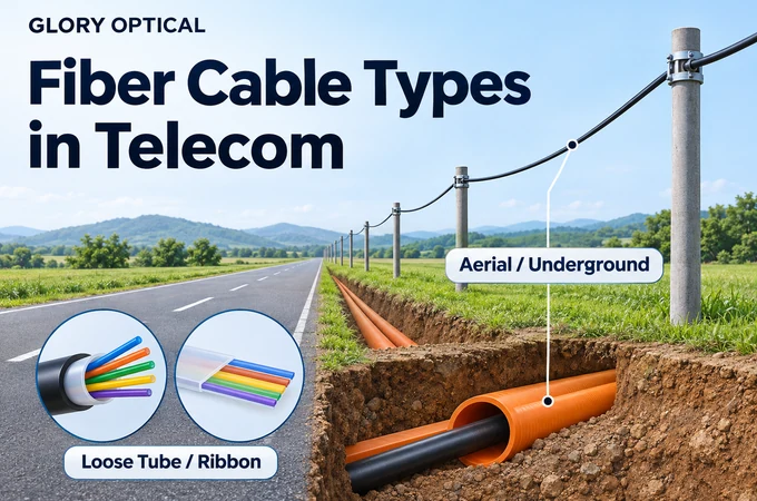

Start by separating the internal construction from the installation method. Loose tubes describe how fibers are protected; ribbons describe how fibers are grouped. Aerial and underground describe where and how the cable is placed. A ribbon can also be housed in a tube, so even the construction terms are not always opposites.

For an ISP planner, contractor or procurement team, the useful question is which complete cable design suits the route and the work that follows. This guide connects the familiar labels to branching, splicing, enclosure compatibility and repair. The aim is a specification that a supplier can answer and a field crew can use.
The four labels describe different decisions
A list of cable types is a convenient introduction, but a purchasing specification needs several fields. The glass has an optical category. The cable has a buffer architecture, a fiber arrangement and a protective construction. The installation adds its own mechanical and environmental requirements. Treating these as separate fields makes quotations easier to compare.

There is a second distinction inside the cable. In ordinary purchasing language, loose tube often means individual coated fibers in buffer tubes, while ribbon cable means fibers joined into groups. That shorthand is useful if both parties understand it. It becomes unreliable when a supplier offers ribbon units inside tubes or a flexible ribbon design. Ask for a cross section and a description of the fiber organization.
The installation description needs equal care. A cable suitable for lashing to a support strand is not automatically self supporting. A cable intended for a protective duct is not automatically suitable for direct contact with soil. IEC 60794-3-10 covers a family of duct, directly buried and lashed aerial cables; the name of that family does not mean every product meets every application.
My starting point would be a route drawing with each change of installation marked. Then I would add the access and splice locations. That exercise tends to expose missing decisions earlier than a comparison of catalog photographs. It also shows where one cable design might serve several sections and where a deliberate transition deserves a place in the budget.
Loose tube cable and selective fiber access
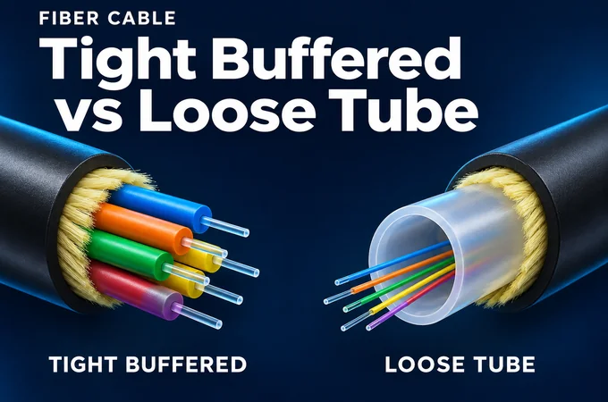
In a typical loose tube design, coated fibers sit within protective buffer tubes rather than being individually tight buffered. The construction allows the fibers some mechanical separation from cable loads. Water blocking may use gel, dry materials or a combination. These are construction details to confirm on the actual product, not features guaranteed by a photograph of colored tubes.
On a distribution route, selective access deserves close attention. Suppose several branches leave a feeder at different locations. A crew may need to access one group while organizing the unused fibers for later work. The practical value of the cable then depends on the tube layout, access procedure, identification and available enclosure space.
Tube organization affects the work at each branch
Two cables with the same total fiber count can divide those fibers differently. A more compact arrangement may reduce cable diameter while putting more fibers in each tube. That changes how much material the technician handles when a small branch is opened. Corning documents both conventional and higher density tube groupings in its microcable guidance.
| Check | Why the answer matters |
|---|---|
| Fibers per tube and identification | Shows how branch fibers are grouped and how unused fibers will be traced. |
| Midspan access procedure | Shows how an uncut cable can be opened and its continuing tubes managed. |
| Water blocking and preparation | Determines the approved cleaning and handling process at the closure. |
| Tube routing and storage limits | Establishes whether the planned closure can hold the required uncut length. |
The table is a set of questions for a sample review. It does not make loose tube the default winner for every access network. A compact design can be valuable in a crowded route, and a familiar design can still be awkward in a small closure. The branch plan and a physical preparation trial are better evidence than familiarity alone.
Keep the comparison tied to the route
Lay the branch schedule beside the cable drawing. How many fibers are opened at each point? Which fibers remain untouched? Where will uncut tubes be stored? If the supplier cannot demonstrate that sequence with the proposed closure, the quotation is missing information that can affect installation cost.
Loose tube also does not have a universal fiber count ceiling. Product families differ in density, diameter and handling limits. Rejecting it solely because a project has a relatively high count can remove a workable option before the actual constraints have been checked.
Ribbon cable and the value of grouped splicing
Ribbon cable groups fibers so a compatible mass fusion process can splice several together. A conventional ribbon holds fibers in a flat array. Flexible or rollable designs use intermittent bonding so the group can conform during routing and storage. The preparation method depends on the ribbon and the approved splicing equipment.

The attraction is strongest when many fibers must be joined at the same location. But the number of fibers in the cable is only a starting point. The useful calculation includes how many will be spliced, how often a closure is revisited and what equipment the maintenance team can mobilize. A high count through cable with few immediate splices presents a different workload from a feeder that is fully joined at several closures.
For 288 fibers joined in complete twelve fiber groups, the plan contains 24 group splice operations instead of 288 individual operations. That arithmetic does not promise a twelvefold reduction in project time. Cable opening, preparation, identification, tray routing, testing and records still take time. Time a supplier demonstration from cable opening to a tested, stored splice, including preparation and rework.
Modern compact ribbon products introduce another procurement detail: coating diameter, ribbon pitch and splicer compatibility. Corning identifies specific compatibility features for its Flow Ribbon products. Those features are useful evidence for those products, not a general assurance that every small diameter ribbon fits existing holders and tools.
I would choose ribbon when its measured benefit in the planned splice workflow justifies the equipment, training and enclosure arrangements. That is a more useful argument than calling ribbon the automatic upgrade from loose fibers.
Aerial cable needs a defined support system
Aerial describes an installation family, not a single cable construction. The support may be a separate messenger, an integrated messenger or the cable itself. The distinction determines how loads reach the poles and which fittings are needed. The internal fiber organization is a further choice.
| Support arrangement | What needs to be established |
|---|---|
| Lashed to a messenger | The approved supporting strand, lashing arrangement, attachments and cable suitability. |
| Integrated messenger such as figure 8 | The messenger construction, span design, attachment method and separation procedure. |
| All dielectric self supporting cable | The cable specific span and loading design, compatible fittings and installation procedure. |
The phrase suitable for a 100 m span is incomplete without its conditions. Span length, route angles, loading assumptions and permissible tension belong together. A longer span or a change in the assumed environment can change the design. AFL therefore provides sag and tension information for its ADSS cables rather than treating the cable name as the complete installation instruction.
Order the hardware against the selected cable
For ADSS, check the actual cable diameter against the fittings, including suspension and dead end arrangements. Review pulling grips and installation equipment too. AFL specifically calls for equipment and hardware that are appropriate for ADSS and for the correct diameter range. Its guide also requires route planning and controlled sagging and tensioning.
This makes hardware a purchasing dependency. If a cable substitution changes diameter, jacket construction or mechanical characteristics, the original clamp list should be reviewed. Keeping the fiber count unchanged does not establish that the old fittings remain suitable.
Decide what maintenance access will look like
For the quotation review, sketch one future repair. Identify where the crew can reach the cable, how slack will be lowered and where splicing can be performed. Then ask whether the closure and slack storage arrangement support that plan. This is an operational review, so it should involve the team expected to restore service.
Electrical corridors need their own assessment. The outdoor cable scope in IEC 60794-3 explicitly notes that additional requirements may be necessary near overhead power lines. An all dielectric construction does not eliminate that design task.
Where usable poles and access rights exist, include aerial construction in the cost comparison. Account for surveys, make ready work, attachments, hardware, construction access and maintenance. A low cable price cannot establish an advantage over the underground alternative until those route costs are included.
Underground routes include duct and direct burial
A cable below ground may sit inside a duct, inside a microduct or directly in soil. These arrangements place different demands on the cable and on future repair. Calling all of them underground hides the part of the specification that the installer most needs to know.
Duct suitability includes the installation process
For a pulled cable, review the intended route and the product handling limits with the installation contractor. For an air assisted microcable, cable stiffness, diameter, duct geometry, friction and the equipment setup affect placement. Corning describes these as system considerations and recommends protective duct or microduct for the microcables covered by its note.
A smaller diameter can make a candidate attractive without proving that it will travel through the available route. Before ordering, establish the usable internal dimensions, route changes and condition of the existing duct. A drawing that records nominal duct size but omits a restricted section can give the purchasing team a false sense of certainty.
Prysmian's microduct procedure calls for duct inspection, cleaning and verification of restrictions, followed by cable specific equipment setup. It also distinguishes these products from conventional outside plant cable. This supports a practical purchasing condition: approve the cable, duct and installation method together.
| Below ground method | Main review question | Repair consideration |
|---|---|---|
| Duct or conduit | Can the selected cable be installed within its approved handling limits? | Can access points support a repair and a possible replacement pull? |
| Microduct | Are the cable, duct route and air assisted equipment compatible? | Are spare paths, couplers and reinstatement procedures available? |
| Direct burial | Is the complete cable qualified for the soil and mechanical conditions? | Where could a repair section and additional closures be accommodated? |
Direct burial needs its own qualification
Armoring can be part of a direct burial design, but the word armored is not sufficient evidence of suitability. Ask for the intended application and the relevant mechanical and environmental performance of the complete cable. If metallic elements are used, confirm the required bonding and grounding arrangements in the project design.
Water blocking deserves the same precision. An intact sheath, protected cable ends and a sealed closure address different entry paths. Water blocking within a cable is intended to limit longitudinal migration. A damaged jacket or leaking entry still needs attention. Ask which construction was tested, under what conditions and against which pass criterion.
For an expandable network, accessible spare pathways deserve serious consideration. Their value depends on the likelihood of another installation and the difficulty of obtaining access when that work becomes necessary. Put that future installation into the cost comparison so the decision reflects the planned use of the route.
Choose the optical fiber separately
The outside of the cable does not identify the optical fiber inside it. ITU-T G.652 describes single mode fiber and cable characteristics, while G.657 addresses improved bending loss performance. The category and subcategory should appear in the specification alongside the construction and installation requirements.
G.657 category A fibers comply with G.652.D and offer improved macrobending performance. Category B has a different scope and is not necessarily compliant with every G.652.D parameter. The exact category therefore matters. A quotation that simply says bend insensitive fiber leaves an important part of the optical specification open.
A fiber bend value is not a cable handling limit
A small bending radius quoted for a fiber category does not authorize bending the completed cable to that radius. Cable handling also involves its tubes, ribbons, strength members and jacket. Use the selected cable's limits for installation and installed conditions. Prysmian's procedure, for example, gives cable level bend limits and other restrictions for the products it covers.
| Specification layer | Evidence to request |
|---|---|
| Optical fiber | Exact ITU category and the specified attenuation at the project wavelengths. |
| Complete cable | Bend radius under load and after installation, tensile limits and temperature ranges. |
| Completed link | The project loss budget, acceptance method and actual measured results. |
Keep the optical budget visible
Consider a planning example for an 8 km point to point segment with six splices and two connector pairs. Assume, only for this calculation, 0.35 dB/km for fiber, 0.10 dB per splice and 0.50 dB per connector pair. The allowance is 2.80 + 0.60 + 1.00 = 4.40 dB before design margin. Adding an assumed 2.00 dB margin gives a planning requirement of 6.40 dB.
These are illustrative inputs, not universal acceptance limits or a claim about a particular cable. Replace them with the specified wavelength, supplier data and project criteria. A PON path would also require its splitter and other component losses. The calculation is useful because it keeps optical performance in view while the team compares mechanical cable designs.
Changing from individual fibers to ribbon does not, by itself, establish support for a particular transmission rate. That decision belongs to the full optical link and its equipment. Conversely, meeting an optical budget does not prove that the cable can survive the intended installation. Both parts of the review must be completed.
Three planning scenarios show the tradeoffs
The following examples are hypothetical design exercises. The fiber counts describe assumed requirements; they are not project results or thresholds for choosing a cable. Each example starts with a different constraint, which is why the same product preference would be a poor answer to all three.
A 96 fiber distribution route with several branches
Assume the route uses existing duct and each branch takes only a small group of fibers. The maintenance team normally works with individual fibers. Compare tube organization, midspan access and the routing of continuing fibers before focusing on splicing speed. A loose fiber design may fit this workflow well, provided the selected cable and closure support the branch plan.
The comparison should still include a suitable flexible ribbon alternative if the supplier can demonstrate convenient selective access. Ask each supplier to prepare the same branch arrangement with the proposed closure. Observe how the continuing fibers are identified and stored. The result to seek is a repeatable task with clear instructions, rather than a preference based on the cable family name.
A 576 fiber connection through constrained duct
Assume substantial splicing is required at both ends and there is little usable space in the existing pathway. The shortlist should include dense ribbon and compact loose fiber designs, with a comparison of actual diameter, installation approval and the completed splice workflow. Mass fusion can be valuable when a large fraction of the cable must be joined, but the available splicer, holders and trays need to be part of the proposal.
The first unresolved question is the pathway itself. If the duct cannot be proved usable, a comparison of nominal cable diameters will not settle the design. A route survey or installation trial may change the shortlist. I would spend that effort before committing to an attractive cable that has no demonstrated installation route.
A 48 fiber rural extension on poles
Assume existing poles are available but their usable span and attachment conditions have not been confirmed. Settle the support architecture first. The choice between lashing, an integrated messenger and ADSS depends on the route design and approved attachments. Loose fibers versus ribbon comes later, informed by the branch and repair workload.
A supplier may offer a cable with a higher span description at a modest premium. That comparison remains incomplete until the loading conditions, route angles and fittings are reconciled. I would ask for one coordinated cable and hardware proposal against the surveyed route, with responsibilities for the engineering decisions made explicit.
These examples suggest a useful rule for procurement: spend effort on the uncertainty that could invalidate the choice. On one route that is selective access. On another it is duct condition. On a third it is the support system. A general ranking of cable types cannot resolve those different problems.
Make the closure part of the cable choice
Cable and closure selection meet at several physical interfaces. The sheath must fit the entry and seal. The strength member needs an approved retention arrangement. Tubes or ribbons need a route into storage and splice trays. The assembly must still allow the intended reentry and repair. A matching total fiber count checks only one part of that relationship.

Published capacity also needs a definition. Corning's closure guide lists separate capacities for single fiber and mass fusion arrangements. AFL's tray instructions distinguish configurations by splice modules and ribbon type. A headline fiber capacity therefore cannot establish the tray arrangement needed for a particular cable.
There is a difference between fitting the planned splice count and having enough room to work on it. Reserve space for the next branch, a repair sleeve and the material moved during reentry. Make that allowance visible in the assembly review rather than assuming it from an unused tray position.
For a sample review, request one assembled branch or splice using the proposed cable, closure, trays and sleeves. Include the intended uncut material and the planned allowance for future work. Open and close the tray system, check the routing and retain photographs with the agreed parts list.
That review creates a useful boundary for substitutions. A change in cable diameter, strength member, ribbon format or coating diameter should trigger a check of the affected interfaces. There may be no difficulty at all. The point is to establish compatibility before the crew discovers a different preparation task at the installation site.
Write an RFQ that can be checked
A good request for quotation gives suppliers enough information to propose a cable and enough structure for the buyer to compare alternatives. It should also distinguish fixed requirements from items that remain subject to route design. Otherwise, a supplier may fill in an unknown with an assumption that the project team never intended.
| RFQ item | State or request |
|---|---|
| Application and route | Installation method for each section, route conditions and planned branch or splice locations. |
| Fiber and organization | Fiber count, ITU category, coating diameter, fibers per tube or ribbon, and identification scheme. |
| Cable construction | Cross section, nominal diameter and tolerance, mass, jacket, strength members, armor and water blocking. |
| Handling and environment | Installation and operating temperature ranges, tensile and crush performance, and bend limits under the specified conditions. |
| Installation system | For aerial work, the coordinated cable and hardware proposal; for duct work, the proposed placement method and compatibility review. |
| Closure interface | Cable entry range, seal and retention parts, tray and sleeve configuration, slack and midspan requirements. |
| Evidence and delivery | Applicable standard edition, tests and pass criteria, traceable reports, reel lengths, labeling and optical acceptance plan. |
Instead of asking for 144F outdoor cable, a more useful opening would be: 144 fiber single mode cable for installation in the surveyed existing duct route, with individual fibers in loose tubes, the project specified ITU category, and documented compatibility with the proposed placement method and closure assembly. Follow that sentence with the measured route information and the required performance schedule.
Name the evidence behind compliance
A statement such as complies with IEC 60794 needs detail. IEC 60794-3 is an outdoor sectional specification, and IEC 60794-3-10 addresses a particular application family. Ask which parts and editions apply, which tests were performed, what limits were used and how the tested construction relates to the offered product.
Keep commercial comparison separate from unresolved technical assumptions. If one quotation includes fittings, tests or closure accessories and another does not, reconcile the scope before judging the price difference. Ask the supplier to list proposed deviations explicitly and attach the agreed construction and interface details to the order.
This creates a practical reference for delivery inspection and future substitution. It is far easier to review a changed diameter or tray arrangement against an agreed schedule than to reconstruct what the word outdoor was supposed to mean.
Verify the delivered cable and the installed link
Selection becomes useful only when it can be checked. At delivery, compare reel identification and the supplied records with the agreed construction. Review visible damage and maintain traceability to the intended route section. Manufacturer procedures such as AFL's ADSS guide and Prysmian's microduct instructions include receipt or preinstallation checks. Use the procedure applicable to the selected product.
During installation, retain the information needed to explain what happened: the route, cable and reel identity, the relevant placing records, splice identification and any approved deviation. A future technician should be able to connect the physical plant with its test files without depending on the memory of the installation crew.
For optical acceptance, define the measurement methods and limits before work begins. A light source and power meter or optical loss test set measures end to end insertion loss. An optical time domain reflectometer locates and characterizes events along the link. When splice loss is evaluated using OTDR measurements, bidirectional assessment helps address differences in backscatter. These measurements answer different questions.
A fusion splicer estimate is useful process information, but it does not measure the complete installed link. The handover should contain the results required by the project, identified by fiber, wavelength and test setup, together with the route and splice records. A pass label without that context is difficult to review and less useful during a fault.
Questions that often hold up a purchase
Can ribbon cable be installed aerially?
Yes, when the complete cable is suitable for the specified aerial arrangement. Ribbon describes the grouping of fibers; it does not establish the support system.
Does underground mean direct burial?
No. A below ground route may use duct or microduct. Direct burial is a separate application to verify on the offered construction.
Is there a fiber count where ribbon always wins?
No universal cutoff resolves the decision. Compare the actual splices, selective access, pathway space, tools and repair workload.
Can the existing closure stay when the cable changes?
Only after checking the affected entry, retention, routing and tray interfaces. Published capacity alone is insufficient.
The decision that matters
The most useful cable specification explains how the product will be installed, accessed, joined and repaired. Start with the route, then connect the internal construction to those tasks. Once the supplier and the field team can work through the same plan, loose tube, ribbon, aerial and underground become useful descriptions of a design that has actually been considered.