What Is a Fiber Optic Panel?
A fiber optic panel usually refers to the interface that presents fiber adapters at the front of an enclosure. It provides an organized patching point for connectors such as LC, SC or MPO.
A basic adapter panel normally contains no internal breakout assembly. The panel holds the adapters while the fiber connections are made through those adapters.
This makes adapter panels useful when the connector format on the backbone side already matches the connector format required at the patching side.
This architecture does not require an MPO-to-LC cassette if the equipment-side connection remains MPO.
Likewise, an LC adapter panel can be used when incoming fibers are already terminated with LC connectors.
Why the Term "Fiber Panel" Can Be Misleading
"Fiber panel" is not used consistently across vendor catalogs.
It may mean
- An adapter plate
- A front patching panel
- An empty rack chassis
- A complete loaded patch panel
What an RFQ should define
- Empty or loaded chassis
- Module format
- Front connector type
- Rear connector type
Glory Optical, for example, uses the product name Fiber Panels for a 2U sliding rack-mounted system that accepts LGX adapter plates or MPO/MTP cassettes rather than for a simple adapter plate alone.
View Glory Optical Fiber Panels
What Is a Fiber Enclosure?
A fiber enclosure is the physical housing that protects, mounts and organizes fiber connectivity components.
In a data-center rack, an enclosure may provide space for:
- Adapter panels
- MPO/MTP cassettes
- Splice trays
- Cable entry and strain relief
- Slack storage
- Front and rear cable management
The enclosure therefore determines much of the system's physical usability, including rack height, module capacity, access method and cable-routing space.
An enclosure itself does not determine whether the system is LC, SC or MPO. That depends on the modules, panels or adapters installed inside it.
Fixed, Sliding or Modular?
Fixed enclosure
Appropriate for stable installations where connections rarely change and rear access requirements are limited.
Sliding enclosure
Provides easier access to internal fibers and rear connections during maintenance or moves, adds and changes.
Modular enclosure
Accepts removable adapter plates, cassettes or other compatible modules, allowing configurations to change without replacing the chassis.
Selection priority
Start with access, module format and cable routing requirements rather than comparing only the maximum advertised fiber count.
Glory Optical's 1U ODF rack model, for example, is designed to accommodate four removable MPO/MTP cassettes in a 19-inch rack enclosure.
See Glory Optical 1U ODF 19-Inch Rack
What Is a Fiber Cassette?
A fiber cassette is a modular unit installed inside a compatible enclosure or patch-panel chassis.
Unlike a simple adapter panel, a cassette may contain an internal fiber assembly.
This allows a high-fiber-count backbone trunk to be converted into individual duplex connections without field-terminating every fiber inside the rack.
That architecture is especially useful where pre-terminated MPO/MTP trunks are used between racks while switches, servers or equipment-side patch cords still require LC duplex interfaces.
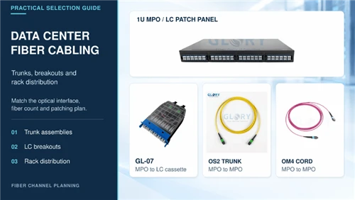
See Glory Optical Data Center Fiber Cabling Solution
A Cassette Is More Than a Box of Adapters
When purchasing a cassette, the exterior shape is only one part of the specification.
A cassette that physically fits into the chassis can still be wrong for the network if its fiber mapping or MPO configuration does not match the trunk.
Fiber Panel vs Enclosure vs Cassette: Quick Comparison
| Component | Main Role | Usually Contains Internal Fiber? | Typical Decision | Best Fit |
|---|---|---|---|---|
| Adapter panel | Presents connector ports | No | Connector type and port count | Direct LC, SC or MPO patching |
| Fiber enclosure | Houses and protects components | Not necessarily | Rack size, access and module capacity | Structured rack management |
| Fiber cassette | Breakout or interface module | Often yes | Fiber mapping, polarity and connector conversion | MPO-to-LC modular systems |
Panel
Interface
Presents the required connector ports.
Enclosure
Structure
Holds, protects and organizes connectivity components.
Cassette
Function
Provides modular breakout or connector transition.
This is a useful rule of thumb, but buyers should always check the supplier's drawing because terminology differs between manufacturers.
How Do the Three Components Work Together?
Consider a structured connection between two data-center racks.
A typical modular route may be:
In this architecture:
- The enclosure holds the modules.
- The cassettes transition between MPO backbone and LC equipment interfaces.
- The trunk cable carries multiple fibers between racks.
- The front adapters create accessible patching points.
A different network may use:
Here, no cassette-based MPO-to-LC conversion is required.
When Should You Choose an Adapter Panel Instead of a Cassette?
Use an adapter-panel architecture when the same connector format can remain through the patching layer and no internal breakout is required.
Typical examples include:
- Direct MPO-to-MPO structured links
- LC-to-LC termination
- Pass-through patching without fiber breakout
Potential Advantages
- Fewer internal components
- Simpler fiber mapping
- Easier visual verification of the connection path
- Potentially fewer connector interfaces in the channel
When Is a Cassette-Based System the Better Choice?
A cassette-based system becomes attractive when deployment requires modularity, pre-terminated trunks or a controlled transition between multi-fiber and duplex interfaces.
MPO Backbone to LC Equipment
One MPO trunk can be presented as multiple LC duplex ports through a cassette, keeping the backbone compact while preserving familiar LC patching at the equipment side.
Staged Deployment
An enclosure can be installed with unused module positions and populated as additional connections are required.
The chassis does not necessarily need to be replaced when another cassette is added.
Reconfiguration
A modular architecture can make it easier to change the patching configuration without disturbing the installed backbone trunk.
High-Density Rack Cabling
Glory Optical currently offers LGX-compatible rack systems where MPO/MTP cassette modules can be installed into 1U or 2U patch-panel platforms.
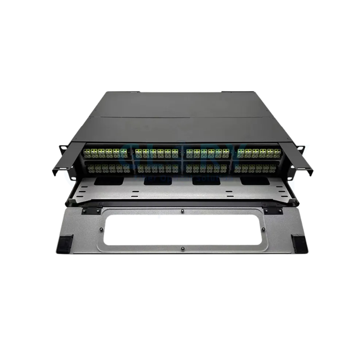
2U Modular Fiber Panel
Sliding rack-mounted platform designed for modular MPO/MTP cassette or adapter-panel configurations.
Best for: higher-capacity modular distribution.

MPO Patch Panel
Rack-mounted fiber management platform combining modular cassette and adapter options for MPO/MTP structured cabling.
Best for: MPO/MTP trunk distribution and breakout systems.
Do Not Select the Enclosure by Port Count Alone
A common procurement mistake is to compare two products only by labels such as "96 ports," "192 fibers" or rack-unit height.
Two 1U products may provide completely different usable systems depending on their module format and connection architecture.
| Question | What to Confirm |
|---|---|
| Rack format | 19-inch compatibility, rack depth and available RU |
| Module format | LGX or another required mechanical format |
| Front interface | LC, SC, MPO/MTP or mixed |
| Rear interface | MPO/MTP, LC, splice pigtail or cable gland |
| Fiber type | OS2, OM3, OM4 or project-specific fiber |
| Fiber count | Required count per module and per enclosure |
| MPO configuration | Fiber count, key orientation and pin configuration |
| Polarity | Required system mapping |
| Access | Fixed, sliding, removable or hinged |
| Cable management | Strain relief, routing and slack-storage space |
| Delivery state | Empty, partially loaded or fully loaded |
Five Buying Mistakes to Avoid
1. Ordering a "Fiber Panel" Without Defining What It Means
Ask whether the quoted item is a front adapter plate, an empty enclosure or a fully loaded patch panel.
The product name alone is not enough.
2. Assuming Every Cassette Fits Every Enclosure
Module dimensions and mounting mechanisms can vary between product families.
Specify the cassette format and compatible chassis in the same BOM.
3. Treating MPO Polarity as a Cable-Only Decision
Polarity must be evaluated across the complete channel.
The trunk, cassette, patch cords and equipment interfaces all contribute to the final fiber mapping.
4. Selecting Maximum Density Without Considering Service Access
A high fiber count is useful only if technicians can identify, inspect and replace connections without disturbing adjacent links.
Drawer access, front/rear cable management and labeling can matter as much as raw capacity.
5. Specifying Connector Type but Not Acceptance Testing
Pre-terminated assemblies should arrive with agreed test requirements.
At minimum, project documents should define the required optical performance, continuity and polarity evidence.
What Should Be Included in an MPO Cassette RFQ?
Instead of requesting only "MPO cassette, 12F", a purchasing specification should identify the complete module configuration.
| RFQ Item | Information to Specify |
|---|---|
| Application | Rack-to-rack backbone, cross-connect or breakout |
| Chassis | Compatible enclosure and module format |
| Fiber | OS2, OM3, OM4 or other project requirement |
| Rear interface | MPO/MTP fiber count and pin configuration |
| Front interface | LC duplex, SC, MPO or other connector |
| Polarity / mapping | Project-defined lane or fiber mapping |
| Quantity | Modules per enclosure and required blank positions |
| Optical requirement | Insertion-loss and return-loss requirement where applicable |
| Labeling | Rack, panel, module and port identification |
| Testing | Continuity, polarity and agreed optical test report |
| Packaging | Module-level and project-level identification |
This approach is more reliable than selecting a cassette from a product photograph alone.
Where Glory Optical Fits Into the Architecture
For buyers building a modular data-center system, Glory Optical's current portfolio covers several layers rather than a single patch-panel product.

Standard Fiber Patch Panel
Drawer-type rack-mounted fiber patch panel designed for fiber connection, distribution and protection with interchangeable adapter-plate options.
Best for: conventional LC, SC and other rack fiber distribution.
Modular MPO Fiber Panel
2U sliding LGX-compatible rack system designed to accept adapter plates or MTP/MPO cassette modules.
Best for: modular higher-fiber-count rack distribution.
1U Modular MPO Platform
Compact rack platform designed for modular cassette-based fiber distribution where rack space is limited.
Best for: 1U modular data-center deployment.
Data Center Fiber Cabling Solution
System-level approach covering MPO/MTP trunks, patching and modular MPO-to-LC transition architectures.
Best for: projects where trunks, cassettes and polarity must be designed as one system.
Which One Should You Choose?
Choose an Adapter Panel When
You need a clean connector interface and the backbone does not require internal fiber breakout.
Choose an Enclosure When
You need the physical rack platform for protecting, routing and organizing fiber connectivity components.
Choose a Cassette When
You need a modular internal fiber assembly, especially an MPO/MTP-to-LC transition.
Choose a Complete System When
The project combines pre-terminated trunks, multiple connector formats, polarity requirements and staged rack deployment.
In many structured cabling systems, you do not choose only one component.
You choose an enclosure and then decide whether each module position should contain an adapter panel, a cassette or another supported fiber-management component.
Final Procurement Rule
"We need a 1U fiber panel."
Start with the optical path:
Once that path is defined, the required panel, enclosure and cassette configuration becomes much easier to specify.
For data-center projects involving MPO/MTP trunks, LC breakouts or staged migration, Glory Optical can configure patch-panel size, cassette quantity, connector interface, fiber type, polarity and labeling around the project BOM.
Explore Glory Optical Data Center Cabling Products
FAQ
Q: Can any MPO cassette be installed in any fiber enclosure?
A: No. Mechanical dimensions, mounting format and module interfaces must match the enclosure. Confirm chassis compatibility before ordering even when the connector specification is otherwise correct.
Q: Do I always need a cassette when using MPO/MTP trunks?
A: No. If the backbone and equipment-side interfaces both remain MPO/MTP, an MPO adapter panel may provide a simpler pass-through architecture. Cassettes are particularly useful when an MPO/MTP backbone must break out to LC, SC or another equipment-side interface.
Q: Is a fiber enclosure the same as a fiber patch panel?
A: The terms often overlap in vendor catalogs. In procurement documents, it is better to describe whether the product is an empty rack enclosure, an adapter-panel chassis or a complete loaded patch panel.
Q: What information should be tested before an MPO system is accepted?
A: Acceptance should verify the required fiber mapping or polarity, optical continuity and project-defined optical performance. Connector end faces should also be inspected using an appropriate inspection process. Visual inspection should complement rather than replace optical performance testing.